自动化英文文献
自动化专业毕业论文外文文献翻译

目录Part 1 PID type fuzzy controller and parameters adaptive method (1)Part 2 Application of self adaptation fuzzy-PID control for main steam temperature control system in power station (7)Part 3 Neuro-fuzzy generalized predictive control of boiler steam temperature ..................................................................... (13)Part 4 为Part3译文:锅炉蒸汽温度模糊神经网络的广义预测控制21Part 1 PID type fuzzy controller and Parametersadaptive methodWu zhi QIAO, Masaharu MizumotoAbstract: The authors of this paper try to analyze the dynamic behavior of the product-sum crisp type fuzzy controller, revealing that this type of fuzzy controller behaves approximately like a PD controller that may yield steady-state error for the control system. By relating to the conventional PID control theory, we propose a new fuzzy controller structure, namely PID type fuzzy controller which retains the characteristics similar to the conventional PID controller. In order to improve further the performance of the fuzzy controller, we work out a method to tune the parameters of the PID type fuzzy controller on line, producing a parameter adaptive fuzzy controller. Simulation experiments are made to demonstrate the fine performance of these novel fuzzy controller structures.Keywords: Fuzzy controller; PID control; Adaptive control1. IntroductionAmong various inference methods used in the fuzzy controller found in literatures , the most widely used ones in practice are the Mamdani method proposed by Mamdani and his associates who adopted the Min-max compositional rule of inference based on an interpretation of a control rule as a conjunction of the antecedent and consequent, and the product-sum method proposed by Mizumoto who suggested to introduce the product and arithmetic mean aggregation operators to replace the logical AND (minimum) and OR (maximum) calculations in the Min-max compositional rule of inference.In the algorithm of a fuzzy controller, the fuzzy function calculation is also a complicated and time consuming task. Tagagi and Sugeno proposed a crisp type model in which the consequent parts of the fuzzy control rules are crisp functional representation or crisp real numbers in the simplified case instead of fuzzy sets . With this model of crisp real number output, the fuzzy set of the inference consequence willbe a discrete fuzzy set with a finite number of points, this can greatly simplify the fuzzy function algorithm.Both the Min-max method and the product-sum method are often applied with the crisp output model in a mixed manner. Especially the mixed product-sum crisp model has a fine performance and the simplest algorithm that is very easy to be implemented in hardware system and converted into a fuzzy neural network model. In this paper, we will take account of the product-sum crisp type fuzzy controller.2. PID type fuzzy controller structureAs illustrated in previous sections, the PD function approximately behaves like a parameter time-varying PD controller. Since the mathematical models of most industrial process systems are of type, obviously there would exist an steady-state error if they are controlled by this kind of fuzzy controller. This characteristic has been stated in the brief review of the PID controller in the previous section.If we want to eliminate the steady-state error of the control system, we can imagine to substitute the input (the change rate of error or the derivative of error) of the fuzzy controller with the integration of error. This will result the fuzzy controller behaving like a parameter time-varying PI controller, thus the steady-state error is expelled by the integration action. However, a PI type fuzzy controller will have a slow rise time if the P parameters are chosen small, and have a large overshoot if the P or I parameters are chosen large. So there may be the time when one wants to introduce not only the integration control but the derivative control to the fuzzy control system, because the derivative control can reduce the overshoot of the system's response so as to improve the control performance. Of course this can be realized by designing a fuzzy controller with three inputs, error, the change rate of error and the integration of error. However, these methods will be hard to implement in practice because of the difficulty in constructing fuzzy control rules. Usually fuzzy control rules are constructed by summarizing the manual control experience of an operator who has been controlling the industrial process skillfully and successfully. The operator intuitively regulates the executor to control the process by watching theerror and the change rate of the error between the system's output and the set-point value. It is not the practice for the operator to observe the integration of error. Moreover, adding one input variable will greatly increase the number of control rules, the constructing of fuzzy control rules are even more difficult task and it needs more computation efforts. Hence we may want to design a fuzzy controller that possesses the fine characteristics of the PID controller by using only the error and the change rate of error as its inputs.One way is to have an integrator serially connected to the output of the fuzzy controller as shown in Fig. 1. In Fig. 1,1K and 2K are scaling factors for e and ~ respectively, and fl is the integral constant. In the proceeding text, for convenience, we did not consider the scaling factors. Here in Fig. 2, when we look at the neighborhood of NODE point in the e - ~ plane, it follows from (1) that the control input to the plant can be approximated by(1)Hence the fuzzy controller becomes a parameter time-varying PI controller, itsequivalent proportional control and integral control components are BK2D and ilK1 P respectively. We call this fuzzy controller as the PI type fuzzy controller (PI fc). We can hope that in a PI type fuzzy control system, the steady-state error becomes zero.To verify the property of the PI type fuzzy controller, we carry out some simulation experiments. Before presenting the simulation, we give a description of the simulation model. In the fuzzy control system shown in Fig. 3, the plant model is a second-order and type system with the following transfer function:)1)(1()(21++=s T s T K s G (2) Where K = 16, 1T = 1, and 2T = 0.5. In our simulation experiments, we use thediscrete simulation method, the results would be slightly different from that of a continuous system, the sampling time of the system is set to be 0.1 s. For the fuzzy controller, the fuzzy subsets of e and d are defined as shown in Fig. 4. Their coresThe fuzzy control rules are represented as Table 1. Fig. 5 demonstrates the simulation result of step response of the fuzzy control system with a Pl fc. We can see that the steady-state error of the control system becomes zero, but when the integration factor fl is small, the system's response is slow, and when it is too large, there is a high overshoot and serious oscillation. Therefore, we may want to introduce the derivative control law into the fuzzy controller to overcome the overshoot and instability. We propose a controller structure that simply connects the PD type and the PI type fuzzy controller together in parallel. We have the equivalent structure of that by connecting a PI device with the basic fuzzy controller serially as shown in Fig.6. Where ~ is the weight on PD type fuzzy controller and fi is that on PI type fuzzy controller, the larger a/fi means more emphasis on the derivative control and less emphasis on the integration control, and vice versa. It follows from (7) that the output of the fuzzy controller is(3)3. The parameter adaptive methodThus the fuzzy controller behaves like a time-varying PID controller, its equivalent proportional control, integral control and derivative control components are respectively. We call this new controller structure a PID type fuzzy controller (PID fc). Figs. 7 and 8 are the simulation results of the system's step response of such control system. The influence of ~ and fl to the system performance is illustrated. When ~ > 0 and/3 = 0, meaning that the fuzzy controller behaves like PD fc, there exist a steady-state error. When ~ = 0 and fl > 0, meaning that the fuzzy controller behaves like a PI fc, the steady-state error of the system is eliminated but there is a large overshoot and serious oscillation.When ~ > 0 and 13 > 0 the fuzzy controller becomes a PID fc, the overshoot is substantially reduced. It is possible to get a comparatively good performance by carefully choosing the value of αandβ.4. ConclusionsWe have studied the input-output behavior of the product-sum crisp type fuzzy controller, revealing that this type of fuzzy controller behaves approximately like a parameter time-varying PD controller. Therefore, the analysis and designing of a fuzzy control system can take advantage of the conventional PID control theory. According to the coventional PID control theory, we have been able to propose some improvement methods for the crisp type fuzzy controller.It has been illustrated that the PD type fuzzy controller yields a steady-state error for the type system, the PI type fuzzy controller can eliminate the steady-state error. We proposed a controller structure, that combines the features of both PD type and PI type fuzzy controller, obtaining a PID type fuzzy controller which allows the control system to have a fast rise and a small overshoot as well as a short settling time.To improve further the performance of the proposed PID type fuzzy controller, the authors designed a parameter adaptive fuzzy controller. The PID type fuzzy controller can be decomposed into the equivalent proportional control, integral control and the derivative control components. The proposed parameter adaptive fuzzy controller decreases the equivalent integral control component of the fuzzy controller gradually with the system response process time, so as to increase the damping of the system when the system is about to settle down, meanwhile keeps the proportional control component unchanged so as to guarantee quick reaction against the system's error. With the parameter adaptive fuzzy controller, the oscillation of the system is strongly restrained and the settling time is shortened considerably.We have presented the simulation results to demonstrate the fine performance of the proposed PID type fuzzy controller and the parameter adaptive fuzzy controller structure.Part 2 Application of self adaptation fuzzy-PID control for main steam temperature control system inpower stationZHI-BIN LIAbstract: In light of the large delay, strong inertia, and uncertainty characteristics of main steam temperature process, a self adaptation fuzzy-PID serial control system is presented, which not only contains the anti-disturbance performance of serial control, but also combines the good dynamic performance of fuzzy control. The simulation results show that this control system has more quickly response, better precision and stronger anti-disturbance ability.Keywords:Main steam temperature;Self adaptation;Fuzzy control;Serial control1. IntroductionThe boiler superheaters of modem thermal power station run under the condition of high temperature and high pressure, and the superheater’s temperature is highest in the steam channels.so it has important effect to the running of the whole thermal power station.If the temperature is too high, it will be probably burnt out. If the temperature is too low ,the efficiency will be reduced So the main steam temperature mast be strictly controlled near the given value.Fig l shows the boiler main steam temperature system structure.Fig.1 boiler main steam temperature systemIt can be concluded from Fig l that a good main steam temperature controlsystem not only has adequately quickly response to flue disturbance and load fluctuation, but also has strong control ability to desuperheating water disturbance. The general control scheme is serial PID control or double loop control system with derivative. But when the work condition and external disturbance change large, the performance will become instable. This paper presents a self adaptation fuzzy-PID serial control system. which not only contains the anti-disturbance performance of serial control, but also combines the good dynamic character and quickly response of fuzzy control .1. Design of Control SystemThe general regulation adopts serial PID control system with load feed forward .which assures that the main steam temperature is near the given value 540℃in most condition .If parameter of PID control changeless and the work condition and external disturbance change large, the performance will become in stable .The fuzzy control is fit for controlling non-linear and uncertain process. The general fuzzy controller takes error E and error change ratio EC as input variables .actually it is a non-linear PD controller, so it has the good dynamic performance .But the steady error is still in existence. In linear system theory, integral can eliminate the steady error. So if fuzzy control is combined with PI control, not only contains the anti-disturbance performance of serial control, but also has the good dynamic performance and quickly response.In order to improve fuzzy control self adaptation ability, Prof .Long Sheng-Zhao and Wang Pei-zhuang take the located in bringing forward a new idea which can modify the control regulation online .This regulation is:]1,0[,)1(∈-+=αααEC E UThis control regulation depends on only one parameter α.Once αis fixed .the weight of E and EC will be fixed and the self adaptation ability will be very small .It was improved by Prof. Li Dong-hui and the new regulation is as follow;]1,0[,,,3,)1(2,)1(1,)1(0,)1({321033221100∈±=-+±=-+±=-+=-+=ααααααααααααE EC E E EC E E EC E E EC E UBecause it is very difficult to find a self of optimum parameter, a new method is presented by Prof .Zhou Xian-Lan, the regulation is as follow:)0(),ex p(12>--=k ke αBut this algorithm still can not eliminate the steady error .This paper combines this algorithm with PI control ,the performance is improved .2. Simulation of Control System3.1 Dynamic character of controlled objectPapers should be limited to 6 pages Papers longer than 6 pages will be subject to extra fees based on their length .Fig .2 main steam temperature control system structureFig 2 shows the main steam temperature control system structure ,)(),(21s W s W δδare main controller and auxiliary controller,)(),(21s W s W o o are characters of the leading and inertia sections,)(),(21s W s W H H are measure unit.3.2 Simulation of the general serial PID control systemThe simulation of the general serial PID control system is operated by MATLAB, the simulation modal is as Fig.3.Setp1 and Setp2 are the given value disturbance and superheating water disturb & rice .PID Controller1 and PID Controller2 are main controller and auxiliary controller .The parameter value which comes from references is as follow :667.37,074.0,33.31)(25)(111111122===++===D I p D I p p k k k s k sk k s W k s W δδFig.3. the general PID control system simulation modal3.3 Simulation of self adaptation fuzzy-PID control system SpacingThe simulation modal is as Fig 4.Auxiliary controller is:25)(22==p k s W δ.Main controller is Fuzzy-PI structure, and the PI controller is:074.0,33.31)(11111==+=I p I p k k s k k s W δFuzzy controller is realized by S-function, and the code is as fig.5.Fig.4. the fuzzy PID control system simulation modalFig 5 the S-function code of fuzzy control3.4 Comparison of the simulationGiven the same given value disturbance and the superheating water disturbance,we compare the response of fuzzy-PID control system with PID serial control system. The simulation results are as fig.6-7.From Fig6-7,we can conclude that the self adaptation fuzzy-PID control system has the more quickly response, smaller excess and stronger anti-disturbance.4. Conclusion(1)Because it combines the advantage of PID controller and fuzzy controller, theself adaptation fuzzy-PID control system has better performance than the general PID serial control system.(2)The parameter can self adjust according to the error E value. so this kind of controller can harmonize quickly response with system stability.Part 3 Neuro-fuzzy generalized predictive controlof boiler steam temperatureXiangjie LIU, Jizhen LIU, Ping GUANAbstract: Power plants are nonlinear and uncertain complex systems. Reliable control of superheated steam temperature is necessary to ensure high efficiency and high load-following capability in the operation of modern power plant. A nonlinear generalized predictive controller based on neuro-fuzzy network (NFGPC) is proposed in this paper. The proposed nonlinear controller is applied to control the superheated steam temperature of a 200MW power plant. From the experiments on the plant and the simulation of the plant, much better performance than the traditional controller is obtained.Keywords: Neuro-fuzzy networks; Generalized predictive control; Superheated steam temperature1. IntroductionContinuous process in power plant and power station are complex systems characterized by nonlinearity, uncertainty and load disturbance. The superheater is an important part of the steam generation process in the boiler-turbine system, where steam is superheated before entering the turbine that drives the generator. Controlling superheated steam temperature is not only technically challenging, but also economically important.From Fig.1,the steam generated from the boiler drum passes through the low-temperature superheater before it enters the radiant-type platen superheater. Water is sprayed onto the steam to control the superheated steam temperature in both the low and high temperature superheaters. Proper control of the superheated steam temperature is extremely important to ensure the overall efficiency and safety of the power plant. It is undesirable that the steam temperature is too high, as it can damage the superheater and the high pressure turbine, or too low, as it will lower the efficiency of the power plant. It is also important to reduce the temperaturefluctuations inside the superheater, as it helps to minimize mechanical stress that causes micro-cracks in the unit, in order to prolong the life of the unit and to reduce maintenance costs. As the GPC is derived by minimizing these fluctuations, it is amongst the controllers that are most suitable for achieving this goal.The multivariable multi-step adaptive regulator has been applied to control the superheated steam temperature in a 150 t/h boiler, and generalized predictive control was proposed to control the steam temperature. A nonlinear long-range predictive controller based on neural networks is developed into control the main steam temperature and pressure, and the reheated steam temperature at several operating levels. The control of the main steam pressure and temperature based on a nonlinear model that consists of nonlinear static constants and linear dynamics is presented in that.Fig.1 The boiler and superheater steam generation process Fuzzy logic is capable of incorporating human experiences via the fuzzy rules. Nevertheless, the design of fuzzy logic controllers is somehow time consuming, as the fuzzy rules are often obtained by trials and errors. In contrast, neural networks not only have the ability to approximate non-linear functions with arbitrary accuracy, they can also be trained from experimental data. The neuro-fuzzy networks developed recently have the advantages of model transparency of fuzzy logic and learning capability of neural networks. The NFN is have been used to develop self-tuning control, and is therefore a useful tool for developing nonlinear predictive control. Since NFN is can be considered as a network that consists of several local re-gions, each of which contains a local linear model, nonlinear predictive control based onNFN can be devised with the network incorporating all the local generalized predictive controllers (GPC) designed using the respective local linear models. Following this approach, the nonlinear generalized predictive controllers based on the NFN, or simply, the neuro-fuzzy generalized predictive controllers (NFG-PCs)are derived here. The proposed controller is then applied to control the superheated steam temperature of the 200MW power unit. Experimental data obtained from the plant are used to train the NFN model, and from which local GPC that form part of the NFGPC is then designed. The proposed controller is tested first on the simulation of the process, before applying it to control the power plant.2. Neuro-fuzzy network modellingConsider the following general single-input single-output nonlinear dynamic system:),1(),...,(),(),...,1([)(''+-----=uy n d t u d t u n t y t y f t y ∆+--/)()](),...,1('t e n t e t e e (1)where f[.]is a smooth nonlinear function such that a Taylor series expansion exists, e(t)is a zero mean white noise and Δis the differencing operator,''',,e u y n n n and d are respectively the known orders and time delay of the system. Let the local linear model of the nonlinear system (1) at the operating point )(t o be given by the following Controlled Auto-Regressive Integrated Moving Average (CARIMA) model:)()()()()()(111t e z C t u z B z t y z A d ----+∆= (2) Where )()(),()(1111----∆=z andC z B z A z A are polynomials in 1-z , the backward shift operator. Note that the coefficients of these polynomials are a function of the operating point )(t o .The nonlinear system (1) is partitioned into several operating regions, such that each region can be approximated by a local linear model. Since NFN is a class of associative memory networks with knowledge stored locally, they can be applied to model this class of nonlinear systems. A schematic diagram of the NFN is shown in Fig.2.B-spline functions are used as the membership functions in theNFN for the following reasons. First, B-spline functions can be readily specified by the order of the basis function and the number of inner knots. Second, they are defined on a bounded support, and the output of the basis function is always positive, i.e.,],[,0)(j k j j k x x λλμ-∉=and ],[,0)(j k j j k x x λλμ-∈>.Third, the basis functions form a partition of unity, i.e.,.][,1)(min,∑∈≡j mam j k x x x x μ(3)And fourth, the output of the basis functions can be obtained by a recurrence equation.Fig. 2 neuro-fuzzy network The membership functions of the fuzzy variables derived from the fuzzy rules can be obtained by the tensor product of the univariate basis functions. As an example, consider the NFN shown in Fig.2, which consists of the following fuzzy rules: IF operating condition i (1x is positive small, ... , and n x is negative large),THEN the output is given by the local CARIMA model i:...)()(ˆ...)1(ˆ)(ˆ01+-∆+-++-=d t u b n t y a t y a t yi i a i in i i i a )(...)()(c i in i b i in n t e c t e n d t u b c b -+++--∆+ (4)or )()()()()(ˆ)(111t e z C t u z B z t yz A i i i i d i i ----+∆= (5) Where )()(),(111---z andC z B z A i i i are polynomials in the backward shift operator 1-z , and d is the dead time of the plant,)(t u i is the control, and )(t e i is a zero mean independent random variable with a variance of 2δ. The multivariate basis function )(k i x a is obtained by the tensor products of the univariate basis functions,p i x A a nk k i k i ,...,2,1,)(1==∏=μ (6)where n is the dimension of the input vector x , and p , the total number of weights in the NFN, is given by,∏=+=nk i i k R p 1)( (7)Where i k and i R are the order of the basis function and the number of inner knots respectively. The properties of the univariate B-spline basis functions described previously also apply to the multivariate basis function, which is defined on the hyper-rectangles. The output of the NFN is,∑∑∑=====p i i i p i ip i i i a y aa yy 111ˆˆˆ (8) 3. Neuro-fuzzy modelling and predictive control of superheatedsteam temperatureLet θbe the superheated steam temperature, and θμ, the flow of spray water to the high temperature superheater. The response of θcan be approximated by a second order model:The linear models, however, only a local model for the selected operating point. Since load is the unique antecedent variable, it is used to select the division between the local regions in the NFN. Based on this approach, the load is divided into five regions as shown in Fig.3,using also the experience of the operators, who regard a load of 200MW as high,180MW as medium high,160MW as medium,140MW as medium low and 120MW as low. For a sampling interval of 30s , the estimated linear local models )(1-z A used in the NFN are shown in Table 1.Fig. 3 Membership function for local modelsTable 1 Local CARIMA models in neuro-fuzzy modelCascade control scheme is widely used to control the superheated steam temperature. Feed forward control, with the steam flow and the gas temperature as inputs, can be applied to provide a faster response to large variations in these two variables. In practice, the feed forward paths are activated only when there are significant changes in these variables. The control scheme also prevents the faster dynamics of the plant, i.e., the spray water valve and the water/steam mixing, from affecting the slower dynamics of the plant, i.e., the high temperature superheater. With the global nonlinear NFN model in Table 1, the proposed NFGPC scheme is shown in Fig.4.Fig. 4 NFGPC control of superheated steam temperature with feed-for-ward control.As a further illustration, the power plant is simulated using the NFN model given in Table 1,and is controlled respectively by the NFGPC, the conventional linear GPC controller, and the cascaded PI controller while the load changes from 160MW to 200MW.The conventional linear GPC controller is the local controller designed for the“medium”operating region. The results are shown in Fig.5,showing that, as expected, the best performance is obtained from the NFGPC as it is designed based on a more accurate process model. This is followed by the conventional linear GPC controller. The performance of the conventional cascade PI controller is the worst, indicating that it is unable to control satisfactory the superheated steam temperature under large load changes. This may be the reason for controlling the power plant manually when there are large load changes.Fig.5 comparison of the NFGPC, conventional linear GPC, and cascade PI controller.4. ConclusionsThe modeling and control of a 200 MW power plant using the neuro-fuzzy approach is presented in this paper. The NFN consists of five local CARIMA models.The out-put of the network is the interpolation of the local models using memberships given by the B-spline basis functions. The proposed NFGPC is similarly constructed, which is designed from the CARIMA models in the NFN. The NFGPC is most suitable for processes with smooth nonlinearity, such that its full operating range can be partitioned into several local linear operating regions. The proposed NFGPC therefore provides a useful alternative for controlling this class of nonlinear power plants, which are formerly difficult to be controlled using traditional methods.Part 4 为Part3译文:锅炉蒸汽温度模糊神经网络的广义预测控制Xiangjie LIU, Jizhen LIU, Ping GUAN摘要:发电厂是非线性和不确定性的复杂系统。
电气工程及其自动化专业_外文文献_英文文献_外文翻译_plc方面.
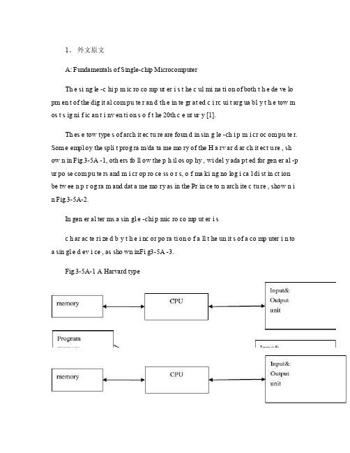
1、外文原文A: Fundamentals of Single-chip MicrocomputerTh e si ng le -c hi p m ic ro co mp ut er i s t he c ul mi na ti on of both t h e de ve lo pm en t of the dig it al com pu te r an d th e in te gr at ed c i rc ui t arg ua bl y t h e tow m os t s ig ni f ic an t i nv en ti on s o f t he 20th c e nt ur y [1].Th es e tow type s of arch it ec tu re are foun d in sin g le -ch i p m i cr oc om pu te r. Som e empl oy the spli t prog ra m/da ta me mo ry of the H a rv ar d ar ch it ect u re , sh ow n in Fig.3-5A -1, oth ers fo ll ow the p h il os op hy , wi del y ada pt ed for gen er al -p ur po se com pu te rs and m i cr op ro ce ss o r s, o f ma ki ng no log i ca l di st in ct ion be tw ee n p r og ra m and dat a me mo ry as in the Pr in ce to n arch ite c tu re , show n i n Fig.3-5A-2.In gen er al ter ms a sin gl e -chi p mic ro co mp ut er i sc h ar ac te ri zed b y t he i nc or po ra ti on of a ll t he un it s of a co mp uter i n to a sin gl e d ev i ce , as sho wn inFi g3-5A -3.Fig.3-5A-1 A Harvard typeFig.3-5A-2. A conventional Princeton computerFig3-5A-3. Principal features of a microcomputerRead only memory (ROM.R OM is usua ll y for the pe rm an ent,n o n-vo la ti le stor a ge of an app lic a ti on s pr og ra m .M an ym i cr oc om pu te rs and m are inte nd e d for high -v ol um e ap pl ic at ions a n d he nc e t h e eco n om ic al man uf act u re of th e de vic e s re qu ir es t h at t he cont en t s o f t he prog ra m me m or y be co mm it t ed perm a ne ntly d u ri ng the man ufa c tu re of ch ip s .Cl ea rl y, thi s im pl ie s a r i go ro us app ro ach to ROM cod e deve l op me nt sin ce cha ng es can not b e mad e afte r manu f a c tu re .Th is dev e lo pm en t proc ess may invo lv e e m ul at io n us in g aso ph is ti ca te d de ve lo pm en t sy ste m wit h a h a rd wa re emu la tio n cap ab il it y as w el l as the use o f po we rf ul s o ft wa re too ls.So me man uf act u re rs pro vi de add it io na l RO M opt i on s by i n cl ud in g in their ra n ge dev ic es wit h (or int en de d fo r use wit h u s er pro gr am ma ble me mo ry. Th e sim p le st of th es e is usu al ly d e vi ce whi ch can op er at e in a micro p ro ce ssor mod e by usi ng som e o f the inp ut /outp u t li ne s as an ad dr es s an d da ta b us fora c ce ss in g ex te rna l mem or y. Thi s t y pe of de vi ce can beh av ef u nc ti on al ly as th e sing le chip mi cr oc om pu te r from whi ch it is d e ri ve d al be it wit h re st ri ct ed I/O and a mod if ied ex te rn al c i rc ui t. The use of thes e d ev ic es is com mo n eve n in prod uc ti on c i rc ui ts wher e t he vo lu me does no tj us ti f y t h e d ev el o pm en t c osts o f c us to m o n -ch i p R OM [2];t he re c a n s ti ll bea s ignif i ca nt saving i n I /O and o th er c h ip s com pa re d to a conv en ti on al mi c ro pr oc es sor b a se d ci rc ui t. Mor e ex ac t re pl ace m en t fo r RO M dev i ce s ca n be o b ta in ed in th e fo rm of va ri an ts w it h 'p ig gy -b ack 'E P RO M(Er as ab le pro gr am ma bl e ROM s oc ke ts or dev ic e s with EPROM i n st ea d o f RO M 。
电气工程及其自动化专业 外文文献 英文文献 外文翻译 plc方面

1、外文原文(复印件)A: Fundamentals of Single-chip MicrocomputerTh e si ng le-ch i p mi cr oc om pu ter is t he c ul mi nat i on o f bo th t h e d ev el op me nt o f th e d ig it al com p ut er an d t he int e gr at ed ci rc ui ta r gu ab ly th e t ow m os t s i gn if ic ant i nv en ti on s o f t h e 20t h c en tu ry[1].Th es e to w typ e s of a rc hi te ctu r e ar e fo un d i n s in gl e-ch ip m i cr oc om pu te r. So m e em pl oy t he sp l it p ro gr am/d ata me mo ry o f th e H a rv ar d ar ch it ect u re, sh ow n i n -5A, ot he rs fo ll ow th e ph i lo so ph y, w i de ly a da pt ed fo r g en er al-p ur pos e c om pu te rs an d m i cr op ro ce ss or s, o f m a ki ng no lo gi c al di st in ct io n b e tw ee n p ro gr am a n d da t a m em ory a s i n th e Pr in cet o n ar ch it ec tu re,sh ow n in-5A.In g en er al te r ms a s in gl e-chi p m ic ro co mp ut er i sc h ar ac te ri zed b y the i nc or po ra tio n of al l t he uni t s o f a co mp ut er i n to a s in gl e dev i ce, as s ho wn in Fi g3-5A-3.-5A-1 A Harvard type-5A. A conventional Princeton computerFig3-5A-3. Principal features of a microcomputerRead only memory (ROM).R OM i s u su al ly f or th e p er ma ne nt, n o n-vo la ti le s tor a ge o f an a pp lic a ti on s pr og ra m .M an ym i cr oc om pu te rs an d mi cr oc on tr ol le r s a re in t en de d fo r h ig h-v ol ume a p pl ic at io ns a nd h en ce t he e co nom i ca l ma nu fa ct ure of t he d ev ic es r e qu ir es t ha t the co nt en ts o f the pr og ra m me mo ry b e co mm it te dp e rm an en tl y d ur in g th e m an uf ac tu re o f c hi ps . Cl ear l y, th is im pl ie sa ri g or ou s a pp roa c h t o R OM co de d e ve lo pm en t s in ce c ha ng es ca nn otb e m ad e af te r man u fa ct ur e .T hi s d e ve lo pm en t pr oce s s ma y in vo lv e e m ul at io n us in g a s op hi st ic at ed deve lo pm en t sy st em w i th a ha rd wa re e m ul at io n ca pa bil i ty a s we ll a s th e u se of po we rf ul so ft wa re t oo ls.So me m an uf act u re rs p ro vi de ad d it io na l RO M opt i on s byi n cl ud in g i n th ei r ra ng e de vi ce s wi th (or i nt en de d fo r us e wi th) u s er pr og ra mm ab le m em or y. Th e s im p le st of th es e i s us ua ll y d ev ice w h ic h ca n op er ate in a m ic ro pr oce s so r mo de b y usi n g so me o f th e i n pu t/ou tp ut li ne s as a n ad dr es s an d da ta b us f or acc e ss in g e xt er na l m e mo ry. T hi s t ype o f d ev ic e c an b e ha ve fu nc ti on al l y a s t he si ng le c h ip mi cr oc om pu te r fr om wh ic h i t i s de ri ve d a lb eit w it h r es tr ic ted I/O an d a mo di fie d e xt er na l ci rcu i t. T he u se o f t h es e RO Ml es sd e vi ce s is c om mo n e ve n in p ro du ct io n c ir cu it s wh er e t he v ol um e do es n o t ju st if y th e d e ve lo pm en t co sts of c us to m on-ch i p RO M[2];t he re c a n st il l b e a si g ni fi ca nt s a vi ng in I/O a nd ot he r c hi ps co mp ar ed t o a c on ve nt io nal mi cr op ro ce ss or b as ed c ir cu it. M o re e xa ctr e pl ac em en t fo r RO M d ev ic es c an b e o bt ai ne d in t he f o rm o f va ri an ts w i th 'pi gg y-ba ck'EP RO M(Er as ab le p ro gr am ma bl e ROM)s oc ke ts o rd e vi ce s w it h EP ROM i ns te ad o f R OM 。
自动化专业 单片机相关 外文文献 英文文献 外文翻译中英对照
本科生毕业论文(外文翻译) 译文名称:MCS -51 系列单片机的功能和结构专业:自动化班次:学员:指导教员:评阅人:完成时间:2022 年11 月30 日Structure and function of the MCS-51 series Structure and function of the MCS-51 series one-chip computer is a name ofa piece of one-chip computer series which Intel Company produces. This company introduced 8 top-grade one-chip computers of MCS-51 series in 1980 after introducing 8 one-chip computers of MCS-48 series in 1976. It belong to alot of kinds this line of one-chip computer the chips have,such as 8051, 8031, 8751, 80C51BH, 80C31BH,etc., their basic composition, basic performance and instruction system are all the same. 8051 daily representatives- 51 serial one-chip computers .An one-chip computer system is made up of several following parts: ( 1) One microprocessor of 8 (CPU). ( 2) At slice data memory RAM (128B/256B),it use not depositting not can reading /data that write, such as result not middle of operation, final result and data wanted to show, etc. ( 3) Procedure memory ROM/EPROM (4KB/8KB ), is used to preserve the procedure , some initial data and form in slice. But does not take ROM/EPROM within some one-chip computers, such as 8031 , 8032, 80C ,etc.. ( 4) Four 8 run side by side I/O interface P0 four P3, each mouth can use as introduction , may use as exporting too. ( 5) Two timer / counter, each timer / counter may set up and count in the way, used to count to the external incident, can set up into a timing way too, and can according to count or result of timing realize the control of the computer. ( 6) Five cut off cutting off the control system of the source . ( 7) One all duplexing serial I/O mouth of UART (universal asynchronous receiver/transmitter (UART) ), is it realize one-chip computer or one-chip computer and serial communication of computer to use for. ( 8) Stretch oscillator and clock produce circuit, quartz crystal finely tune electric capacity need outer. Allow oscillation frequency as 12 megahertas now at most. Every the above-mentioned part was joined through the inside data bus .Among them, CPU is a core of the one-chip computer, it is the control of the computer and command centre, made up of such parts as arithmetic unit and controller , etc.. The arithmetic unit can carryon 8 persons of arithmetic operation and unit ALU of logic operation while including one, the 1 storing device temporarilies of 8, storing device 2 temporarily, 8's accumulation device ACC, register B and procedure state register PSW, etc. Person who accumulate ACC count by 2 input ends entered of checking etc. temporarily as one operation often, come from person who store 1 operation is it is it make operation to go on to count temporarily , operation result and loopback ACC with another one. In addition, ACC is often regarded as the transfer station of data transmission on 8051 inside . The same as general microprocessor, it is the busiest register. Help remembering that agreeing with A expresses in the order. The controller includes the procedure counter , the order is depositted, the order decipher, the oscillator and timing circuit, etc. The procedure counter is made up of counter of 8 for two, amounts to 16. It is a byte address counter of the procedure in fact, the content is the next IA that will carried out in PC. The content which changes it can change the direction that the procedure carries out . Shake the circuit in 8051 one-chip computers, only need outer quartz crystal and frequency to finely tune the electric capacity, its frequency range is its 12MHZ of 1.2MHZ. This pulse signal, as 8051 basic beats of working, namely the minimum unit of time. 8051 is the same as other computers, the work in harmony under the control of the basic beat, just like an orchestra according to the beat play that is commanded.There are ROM (procedure memory , can only read ) and RAM in 8051 slices (data memory, can is it can write ) two to read, they have each independent memory address space, dispose way to be the same with general memory of computer. Procedure 8051 memory and 8751 slice procedure memory capacity 4KB, address begin from 0000H, used for preserving the procedure and form constant. Data 8051- 8751 8031 of memory data memory 128B, address false 00FH, use for middle result to deposit operation, the data are stored temporarily and the data are buffered etc.. In RAM of this 128B, there is unit of 32 byteses that can be appointed as the job register, this and generalmicroprocessor is different, 8051 slice RAM and job register rank one formation the same to arrange the location. It is not very the same that the memory of MCS-51 series one-chip computer and general computer disposes the way in addition. General computer for first address space, ROM and RAM can arrangein different space within the range of this address at will, namely the addressesof ROM and RAM, with distributing different address space in a formation. While visiting the memory, corresponding and only an address Memory unit, can ROM, it can be RAM too, and by visiting the order similarly. This kind of memory structure is called the structure of Princeton. 8051 memories are divided into procedure memory space and data memory space on the physics structure, there are four memory spaces in all: The procedure stores in one and data memory space outside data memory and one in procedure memory space and one outside one, the structure forms of this kind of procedure device and data memory separated form data memory, called Harvard structure. But use the angle from users, 8051 memory address space is divided into three kinds: (1) In the slice, arrange blocks of FFFFH , 0000H of location , in unison outside the slice (use 16 addresses). (2) The data memory address space outside one of 64KB, the address is arranged from 0000H 64KB FFFFH (with 16 addresses ) too to the location. (3) Data memory address space of 256B (use 8 addresses). Three above-mentioned memory space addresses overlap, for distinguishing and designing the order symbol of different data transmission in the instruction system of 8051: CPU visit slice, ROM order spend MOVC , visit block RAM order uses MOVX outside the slice, RAM order uses MOV to visit in slice.8051 one-chip computer have four 8 walk abreast I/O port, call P0, P1, P2 and P3. Each port is 8 accurate two-way mouths, accounts for 32 pins altogether. Every one I/O line can be used as introduction and exported independently. Each port includes a latch (namely special function register ), one exports the driver and a introduction buffer . Make data can latch when outputting, data can buffer when making introduction , but four function of passway these self-same.Expand among the system of memory outside having slice, four port these may serve as accurate two-way mouth of I/O in common use. Expand among the system of memory outside having slice, P2 mouth see high 8 address off; P0 mouth is a two-way bus, send the introduction of 8 low addresses and data / export in timesharingThe circuit of 8051 one-chip computers and four I/O ports is very ingenious in design. Familiar with I/O port logical circuit, not only help to use ports correctly and rationally, and will inspire to designing the peripheral logical circuit of one-chip computer to some extent. Load ability and interface of port have certain requirement, because output grade, P0 of mouth and P1 end output, P3 of mouth grade different at structure, so, the load ability and interface of its door demand to have nothing in common with each other. P0 mouth is different from other mouths, its output grade draws the resistance supremly. When using it as the mouth in common use to use, output grade is it leak circuit to turn on, is it is it urge NMOS draw the resistance on taking to be outer with it while inputting toEvery one with P0 mouth can drive 8 Model LS TTL load to export. P1 mouth is an accurate two-way mouth too, used as I/O in common use. Different from P0 mouth output of circuit its, draw load resistance link with power on inside have. In fact, the resistance is that two effects are in charge of FET and together: One FET is in charge of load, its resistance is regular. Another one can is it lead to work with close at two state, make its President resistance value change approximate 0 or group value heavy two situation very. When it is 0 that the resistance is approximate , can draw the pin to the high level fast ; When resistance value is very large, P1 mouth, in order to hinder the introduction state high. Output as P1 mouth high electricity at ordinary times, can is it draw electric current load to offer outwards, draw the resistance on needn't answer and thenning. Here when the port is used as introduction, must write into 1 to the corresponding latch first too, make FET end. Relatively about 20,000 ohmsbecause of the load resistance in scene and because 40,000 ohms, will not exert an influence on the data that are input. The structure of P2 some mouth is similar to P0 mouth, there are MUX switches. Is it similar to mouth partly to urge, but mouth large a conversion controls some than P1. P3 mouth one multi-functionalthese, make her besides accurate two-way function with P1 mouth just, can alsodetermines to be to output data of latch to output second signal of function. Act as W =At 1 o'clock, output Q end signal; Act as Q =At 1 o'clock, can output W line signal . At the time of programming, it is that the first function is still the second function but needn't have software that set up P3 mouth in advance . It hardware not inside is the automatic to have two function outputted when CPU carries on SFR and seeks the location (the location or the byte ) to visit to P3 mouth /at not lasting lining, there are inside hardware latch Qs =1.The operation principle of P3 mouth is similar to P1 mouth.Output grade , P3 of mouth , P1 of P1 , connect with inside have load resistance of drawing , every one of they can drive 4 Model LS TTL load to output. As while inputting the mouth, any TTL or NMOS circuit can drive P1 of 8051 one-chip computers as P3 mouth in a normal way . Because draw resistance on output grade of them have, can open a way collector too or drain-source resistance is it urge to open a way, do not need to have the resistance of drawing outerly . Mouths are all accurate two-way mouths too. When the conduct is input, must write the corresponding port latch with 1 first . As to 80C51 one-chip computer, port can only offer milliampere of output electric currents, is it output mouth go when urging one ordinary basing of transistor to regard as, should contact a resistance among the port and transistor base , in order to the electricity while restraining the high level from exporting P1~P3 Being restored to the throne is the operation of initializing of an one-chip computer. Its main function is to turn PC into 0000H initially , make theone-chip computer begin to hold the conduct procedure from unit 0000H. Except that the ones that enter the system are initialized normally,as because procedure operate it make mistakes or operate there aren't mistake, in order to extricate oneself from a predicament , need to be pressed and restored to the throne the key restarting too. It is an input end which is restored to the throne the signal in 8051 China RST pin. Restore to the throne signal high level effective , should sustain 24 shake cycle (namely 2 machine cycles ) the above its effective times. If 6 of frequency of utilization brilliant to shake, restore to the throne signal duration should exceed 4 delicate to finish restoring to the throne and operating. Produce the logic picture of circuit which is restored to the throne the signal:Restore to the throne the circuit and include two parts outside in the chip entirely. Outside that circuit produce to restore to the throne signal (RST ) hand over to Schmitt's trigger, restore to the throne circuit sample to output , Schmitt of trigger constantly in each S5P2 , machine of cycle in having one more , then just got and restored to the throne and operated the necessary signal insidly. Restore to the throne resistance of circuit generally, electric capacity parameter suitable for 6 brilliant to shake, can is it restore to the throne signal high level duration greater than 2 machine cycles to guarantee. Being restored to the throne in the circuit is simple, its function is very important. Pieces of one-chip computer system could normal running,should first check it can restore to the throne not succeeding. Checking and can pop one's head and monitor the pin with the oscillograph tentatively, push and is restored to the throne the key, the wave form that observes and has enough range is exported (instantaneous), can also through is it restore to the throne circuit group holding value carry on the experiment to change.MCS -51 系列单片机的功能和结构MCS - 51 系列单片机具有一个单芯片电脑的结构和功能,它是英特尔公司生产的系列产品的名称。
生产自动化毕业论文中英文资料外文翻译文献
生产自动化毕业论文中英文资料外文翻译文献随着科技的不断进步和人们对效率的追求,生产自动化已经成为现代工业的重要组成部份。
生产自动化通过引入先进的机械和电子设备,以及自动化控制系统,实现了生产过程的自动化和智能化。
本文将介绍一些关于生产自动化的研究和应用的外文翻译文献。
1. 文献一:《生产自动化的发展与趋势》这篇文献介绍了生产自动化的发展历程和未来的趋势。
文章指出,生产自动化的发展可以追溯到20世纪初,随着电子技术和计算机技术的不断进步,生产自动化得到了快速发展。
未来,生产自动化将更加注重智能化和柔性化,以适应不断变化的市场需求。
2. 文献二:《生产自动化在汽车创造业中的应用》这篇文献探讨了生产自动化在汽车创造业中的应用。
文章指出,汽车创造业是生产自动化的典型应用领域之一。
通过引入机器人和自动化生产线,汽车创造商可以大大提高生产效率和产品质量。
此外,生产自动化还可以减少人力成本和人为错误。
3. 文献三:《生产自动化对工作环境和员工的影响》这篇文献研究了生产自动化对工作环境和员工的影响。
文章指出,尽管生产自动化可以提高生产效率,但它也带来了一些负面影响。
例如,自动化设备的噪音和振动可能对员工的健康造成影响。
此外,自动化还可能导致一些工人失去工作机会。
因此,为了最大限度地发挥生产自动化的优势,必须采取适当的安全措施和培训计划。
4. 文献四:《生产自动化在食品加工行业中的应用》这篇文献讨论了生产自动化在食品加工行业中的应用。
文章指出,食品加工是一个复杂而繁琐的过程,生产自动化可以大大提高生产效率和产品质量。
通过引入自动化设备和控制系统,食品加工商可以减少人为错误和污染风险。
此外,生产自动化还可以实现对食品生产过程的精确控制和监测。
5. 文献五:《生产自动化在医药创造业中的应用》这篇文献探讨了生产自动化在医药创造业中的应用。
文章指出,医药创造是一个高度精细和复杂的过程,生产自动化可以提高生产效率和产品质量的同时,确保药品的安全和一致性。
自动化专业-外文文献-英文文献-外文翻译-plc方面

1、外文原文(复印件)A: Fundamentals of Single-chip MicrocomputerTh e si ng le-ch i p mi cr oc om pu ter is t he c ul mi nat i on o f bo th t h e d ev el op me nt o f th e d ig it al com p ut er an d t he int e gr at ed ci rc ui ta r gu ab ly th e t ow m os t s i gn if ic ant i nv en ti on s o f t h e 20t h c en tu ry[1].Th es e to w t ype s o f a rc hi te ct ur e a re fo un d i n s i ng le—ch ip m i cr oc om pu te r。
S o me em pl oy th e s p li t p ro gr am/d at a me mo ry of t he H a rv ar d ar ch it ect u re, sh ow n in Fi g.3-5A—1,ot he r s fo ll ow t hep h il os op hy, wi del y a da pt ed f or ge n er al—pu rp os e c o mp ut er s an dm i cr op ro ce ss or s, of ma ki ng no lo gi c al di st in ct io n be tw ee n p ro gr am a n d da ta m em or y a s i n th e Pr in cet o n ar ch it ec tu re,sh ow n in F ig。
3-5A-2.In g en er al te r ms a s in gl e—ch i p mi cr oc om pu ter isc h ar ac te ri zed b y the i nc or po ra tio n of al l t he uni t s o f a co mp ut er i n to a s in gl e de v i ce,as s ho wn i n F ig3—5A—3。
自动化专业相关英文文献加翻译(20000字符)

自动化专业相关英文文献加翻译(20000字符)This chapter continues from the previous chapters on programming and introduces internal relays. A variety of other terms are often used todescribe these elements, such as auxiliary relays, markers, flags, coils, and bit storage. These are one of the elements included among the special built-in functions with PLCs and are very widely used in programming. A small PLC might have a hundred or more internal relays, some of them battery backed so thatthey can be used in situations where it is necessary to ensure safe shutdownof a plant in the event of power failure. Later chapters consider other common built-in elements.7.1 Internal RelaysIn PLCs there are elements that are used to hold data, that is, bits, and behave like relays,being able to be switched on or off and to switch other devices on or off. Hence the term internal relay. Such internal relays do not exist as real-world switching devices but are merely bits in the storage memory that behave in the same way as relays. For programming, they can be treated in the same way as an external relay output and input. Thus inputs to external switches can be used to give an output from an internal relay. This then results in the internal relay contacts being used, in conjunction with other external input switches, to give an output, such as activating a motor. Thus we might have (Figure 7.1)On one rung of the program:Inputs to external inputs activate the internal relay output. On a later rung of the program:As a consequence of the internal relay output, internal relay contacts are activated and socontrol some output.In using an internal relay, it has to be activated on one rung of aprogram and then its output used to operate switching contacts on another rung, or rungs, of the program. Internal relays can be programmed with as many setsof associated contacts as desired.To distinguish internal relay outputs from external relay outputs, theyare given different types of addresses. Different manufacturers tend to use different terms for internal relays andhave different ways of expressing their addresses. For example, Mitsubishi uses the term auxiliary relay or marker and the notation M100, M101, and so on. Siemens uses the term flag and the notation F0.0, F0.1, and so on. Telemecanique uses the term bit and the notation B0, B1, and so on. Toshiba uses the term internal relay and the notation R000, R001, and so on. Allen-Bradley uses the term bit storage and notation in the PLC-5 of the formB3/001,B3/002, and so on. 7.2 Ladder ProgramsWith ladder programs, an internal relay output is represented using the symbol for an output device, namely , with an address that indicates that itis an internal relay. Thus, with a Mitsubishi PLC, we might have the addressM100, the M indicating that it is an internal relay or marker rather than an external device. The internal relay switching contacts are designated with the symbol for an input device, namely , and given the same address as theinternal relay output, such as M100.7.2.1 Programs with Multiple Input ConditionsAs an illustration of the use that can be made of internal relays,consider the following situation. A system is to be activated when twodifferent sets of input conditions are realized.We might just program this as an AND logic gate system; however, if a number of inputs have to be checked in order that each of the input conditions can be realized, it may be simpler to use an internal relay. The first input conditions then are used to give an output to an internal relay. This relay has associated contacts that then become part of the input conditions with the second inputFigure 7.2 shows a ladder program for such a task. For the first rung, wheninput In 1 or input In 3 is closed and input In 2 closed, internal relayIR 1 is activated. This results in the contacts for IR 1 closing. If input In4 is then activated, there is an output from output Out 1. Such a task mightbe involved in the automatic lifting of a barrier when someone approaches from either side. Input In 1 and input In 3 are inputs from photoelectric sensors that detect the presence of a personapproaching or leaving from either side of the barrier, input In 1 being activated from one side of it and input In 3 from the other. Input In 2 is an enabling switch to enable the system to be closed down. Thus when input In 1or input In 3, and input In 2, are activated, there is an output from internal relay 1. This will close the internal relay contacts. If input In 4, perhaps a limit switch,detects that the barrier is closed, then it is activated and closes. The result is then an output fromOut 1, a motor that lifts the barrier. If the limit switch detects thatthe barrier is already open, the person having passed through it, then itopens and so output Out 1 is no longer energized and a counterweight mightthen close the barrier. The internal relay has enabled two parts of theprogram to be linked, one part being the detection of the presence of a person and the second part the detection of whether the barrier is already up or down. Figure 7.3a shows how Figure 7.2 would appear in Mitsubishi notation andFigure 7.3b shows how it would appear in Siemens notation.Figure 7.4 is another example of a ladder program involving internal relays. Output 1 is controlled by two input arrangements. The first rung shows theinternal relay IR 1, which isenergized if input In 1 or In 2 is activated and closed. The second rung shows internal relay IR 2, which is energized if inputs In 3 and In 4 are both energized. The third rung shows that output Out 1 is energized if internalrelay IR 1 or IR 2 is activated. Thus there is an output from the system if either of two sets of input conditions is realized. 7.2.2 Latching ProgramsAnother use of internal relays is for resetting a latch circuit. Figure7.5 shows an example of such a ladder program.When the input In 1 contacts are momentarily closed, there is an output at Out 1. This closes the contacts for Out 1 and so maintains the output, evenwhen input In 1 opens. When input In 2 is closed, the internal relay IR 1 is energized and so opens the IR 1 contacts, which are normally closed. Thus the output Out 1 is switched off and so the output is unlatched.Consider a situation requiring latch circuits where there is an automatic machine that can be started or stopped using push-button switches. A latch circuit is used to start and stop the power being applied to the machine. The machine has several outputs that can be turned on if the power has been turned on and are off if the power is off. It would be possible to devise a ladder diagram that has individually latched controls for each such output. However, a simpler method is to use an internal relay. Figure 7.6 shows such a ladder diagram. The first rung has the latch for keeping the internal relay IR 1 on when the start switch gives a momentary input. The second rung will then switch the power on. The third rung will also switch on and give output Out 2 if the input 2 contacts are closed. The third rung will also switch on and give output Out 3 if the input 3 contacts are closed. Thus all the outputs can be switched on when the start push button is activated. All the outputs will be switched off if the stop switch is opened. Thus all the outputs are latched by IR 1.7.2.3 Response TimeThe time taken between an input occurring and an output changing depends on such factors as the electrical response time of the input circuit, the mechanical response of the output感谢您的阅读,祝您生活愉快。
自动化英文论文参考文献范例

自动化英文论文参考文献一、自动化英文论文期刊参考文献[1].网络办公自动化系统构架设计综述.《中小企业管理与科技》.2009年12期.韩小强.[2].试论办公自动化的发展趋势.《产业与科技论坛》.2011年2期.张娟.[3].办公自动化系统在实际操作中的利弊之我见.《科技创新与应用》.2015年24期.吴胜斌.[4].《自动化学报》第39卷第10期(2013年10月)17篇论文的英文关键词共有6个Ei主题词.《西北工业大学学报》.被中信所《中国科技期刊引证报告》收录ISTIC.被EI 收录EI.被北京大学《中文核心期刊要目总览》收录PKU.2013年6期.胡沛泉.[5].基于OCR与词形状编码的英文扫描文档检索.《模式识别与人工智能》.被中信所《中国科技期刊引证报告》收录ISTIC.被EI收录EI.被北京大学《中文核心期刊要目总览》收录PKU.2009年3期.夏勇.戴汝为.肖柏华.王春恒.[8].Word文档中通过CrossRef自动查询与整合英文参考文献DOI的实践. 《中国科技期刊研究》.被中信所《中国科技期刊引证报告》收录ISTIC.被北京大学《中文核心期刊要目总览》收录PKU.被南京大学《核心期刊目录》收录CSSCI.2013年2期.王玥.毛善锋.刘谦.[9].《自动化学报》征稿简则.《自动化学报》.被中信所《中国科技期刊引证报告》收录ISTIC.被EI收录EI.被北京大学《中文核心期刊要目总览》收录PKU.2001年1期.[10].联机手写英文识别.《计算机研究与发展》.被中信所《中国科技期刊引证报告》收录ISTIC.被EI 收录EI.被北京大学《中文核心期刊要目总览》收录PKU.2006年1期.邹明福.钮兴昱.刘昌平.白洪亮.二、自动化英文论文参考文献学位论文类[1].非母语英文字母识别、汉语数字识别及其应用系统研究.作者:李腾.模式识别与智能系统中国科学院自动化研究所2004(学位年度)[2].英文地址图像识别与翻译研究.被引次数:1作者:屠晓.计算机应用技术华东师范大学2011(学位年度)[3].基于HMM的脱机自由手写英文单词识别系统.作者:梁佳玉.模式识别与智能系统中国科学院自动化研究所2004(学位年度)[4].特征选择方法对英文作文自动评分性能影响的研究.被引次数:4作者:崔爱国.计算机技术苏州大学2009(学位年度)[5].翻译项目实践报告——从“核电站竞标项目书”翻译看工程类标书的英汉翻译.作者:朱奕超.英语笔译东华大学2013(学位年度)[6].孟加拉信封图像的语言辨别和邮政编码定位.作者:周丽君.计算机应用技术华东师范大学2006(学位年度)[7]中英文混合语音合成系统.作者:张毅.模式识别与智能系统中国科学院自动化研究所2009(学位年度)[8]借助网络信息的汉英实体翻译技术研究.被引次数:1作者:杨帆.计算机应用技术中国科学院自动化研究所2009(学位年度)[9].广播电视地球站自动化监控系统的研究.作者:张向明.电子与通信工程山东大学2007(学位年度)[10].基于图像识别和地址翻译的国际信函批译系统.被引次数:2作者:王霞玲.计算机应用技术华东师范大学2009(学位年度)三、自动化英文论文专著参考文献[1]脱机自由手写英文单词的识别.梁佳玉.黄磊.刘迎建,2003中科院自动化研究所自动化与信息技术发展战略研讨会暨2003年学术年会[2]联机手写英文单词识别系统.邹明福.钮兴昱.刘昌平.童剑军,2005中国自动化与信息技术研讨会暨2004年学术年会[3]英文教材材“电路基础(第2版)”与中文教材材“电路(第5版)”的比较研究.罗先觉,2010第七届全国高等学校电气工程及其自动化专业教学改革研讨会[4]词表限制下的非母语连续英文字母串识别系统.李腾.李成荣.李鹏,2003第七届全国人机语音通讯学术会议[5]英文教材《电路基础(第2版)》介绍与评述.罗先觉.王仲奕.王曙鸿.陈斌.闰瑞萍.苏婉莹,2008第五届全国高校电气工程及其自动化专业教学改革研讨会[6]人工智能课程全英文教学改革.谢榕.刘琼.卢冰,20132013年全国智能科学与技术教育暨教学学术研讨会[7]机械工程及自动化专业机械工程导论课程建设.杨培林.庞宣明.陈晓南.曹秉刚,2006第八届全国机械设计教学研讨会议暨见习机械师设计工程师工作会议[8]用于英文字母识别的三种人工神经网络的设计.丛爽.陆婷婷,2006第四届全国信息获取与处理学术会议[9]《高电压技术》双语教学的探讨.刘刚.张尧,2007第四届全国高等学校电气工程及其自动化专业教学改革研讨会[10]一种基于骨架特征和神经网络的手写体字符识别技术.蔡自兴.成浩,2001中国自动化学会中南六省(区)第十九届自动化学术年会。
- 1、下载文档前请自行甄别文档内容的完整性,平台不提供额外的编辑、内容补充、找答案等附加服务。
- 2、"仅部分预览"的文档,不可在线预览部分如存在完整性等问题,可反馈申请退款(可完整预览的文档不适用该条件!)。
- 3、如文档侵犯您的权益,请联系客服反馈,我们会尽快为您处理(人工客服工作时间:9:00-18:30)。
Classification of control systems there are three ways: by automatic classification methods in order to participate in the control mode classification, to adjust the law category.One way to control category1, the open-loop control system if the computer output of open loop control system to exercise control of the production process, but the control results --- the state of the production process does not affect the computer control systems, computer \ controller \ production and other sectors does not constitute a closed loop, is called open-loop control system computer. the production process of the state is no feedback to the computer, but by the operator to monitor the status of the production process, decision control program, and tell the computer to control the role of exercising control.2, closed loop control system computer to the production of an object or process control, the state can directly influence the production process computer control system, called the closed-loop control system computer. Control of the computer monitor in the operator, the automatic acceptance of the production process state test results, calculate and determine the control scheme, the direct command and control units (devices) of action, the role of exercising control of the production process. In such systems, aircraft control components under control of control information sent to control device operation, the other running equipment condition as the output, measured by the detection part, the feedback as input to the control computer; to make control Computer \ Control Components \ production \ test components form a closed loop. We will call this form of control computer control closed-loop control. Closed loop control system computer, using a mathematical model to set the value of the production process and test results of the best value of the deviation between the feedback and control the production process to run at their best.3, line control system as long as the computer controlled production of the controlled object or process, to exercise direct control, without human intervention are called the control computer on-line control, or on-line control system.4, offline control system control computer does not directly participate in the control object or the controlled production process. It only managed to complete the process of the controlled object or the status of testing, and testing of data processing; and then develop control programs, the output control instruction, operator reference control instructions manually controlled operation to control parts of the object orsubject control process control. This control form is called off-line computer control system.5, real-time control system control computer real-time control system is controlled by the control of the object or process, or request when the request processing control, the control function in a timely manner to address and control systems, commonly used in the production process is interrupted for the occasion. Such as steel, each one refining furnace steel is a process; and if the process rolling, rolling out each piece of steel considered a process, each process is repeated. Only enter the process only requires a computer control. Once control of the computer, it requires a computer from the production process information in the required time to respond to or control. Such systems often use sophisticated interrupt system and interrupt handling procedures to achieve. In summary, an online system is not necessarily a real-time system. But a real-time system must be an online system.Second, in order to participate in the control mode to Category1, direct digital control system by the control computer to replace conventional analog instruments and direct regulation to control the production process, as the computer as digital signals, so named after the DDC control. Actually controlled the production process control components, control signals received by the process controller input / output channels of D / (D / A) converter output of the digital control computer volume to be converted into analog; analog input control machine to go through the process of input / output channels of analog / digital (A / D) converter into a digital number into the computer. DDC control systems often use a small computer or microprocessor, the time-sharing system to achieve multiple points of control. Is in fact a discrete sampling with the controller, to achieve discrete multi-point control. DDC computer control system that has become the main control computer control system forms. DDC control of the advantage of flexibility, large, focused on high reliability and low cost. Can use several forms of digital computing circuits, or even dozens of loop production process, integral to proportional --- --- differential (PID) control to maintain the industrial state of the controlled object at a given value, the deviation small and stable. And as long as the change of control algorithms and applications can achieve more complex control. Such as feedforward control and the best control. Under normal circumstances, DDC-level control often more complex as the implementation of advanced control level.2, supervisory computer control system supervisory computer control system fora particular production process, according to the production process of various states, according to the production process of the mathematical model to calculate the best production equipment should be running a given value, and the best value automatically or manually on the DDC Executive-level computer or analog meter to align the regulation or control of the target set. By a DDC or adjust the instrument at various points on the production process (running equipment) to exercise control. SCC system is that it can guarantee the production process is always controlled the situation in the best condition to run, so get the most benefit. SCC results directly affect the merits of the first of its mathematical model, this should always improve the operation process model, and modify the control algorithm, and application control procedures.3, multi-level control systems in modern manufacturing enterprises in the production process not only the need to address the problem of online control, and Huan Zhi Li called for a solution of production problems, the daily product line, the number of arrangements for planning and scheduling, and Rose plans develop a long term planning, notice Xiaoshou prospects, there was multi-level control system. DDC class is mainly used for direct control of the production process, for PID, or feedforward control; SCC level is mainly used for optimal control or adaptive control or learning control calculation, and command and control the same DDC class report back to the MIS class. DDC level usually microcomputers, SCC-level general use of small computers or high-end microcomputers. MIS Workshop main function of governance is based on plant-level production of varieties issued, the number of orders and collect up the production process of the state of information, at any time reasonable schedule to achieve optimal control, command and SCC-level supervisory control. Factory management level MIS main function is to accept the company and factory production tasks assigned by the actual situation of optimized computing, Zhi Ding factory production plans and short-term (ten days or weeks or days) arrangements, and then issued to the plant-level production tasks. Corporate governance level MIS main function is to guess the market demand computing to develop strategic long-term development planning, and contract orders, raw material supply situation and the production conditions, comparison of the optimal production program selection and calculation, work out the entire company business a long time (months or ten days) of the production plan, sales plan, assigned to the task of the factory management level. MIS-level main function is to achieve real-timeinformation processing, decision-makers at all levels to provide useful information, make on the production planning \ scheduling and management programs to plan the coordination and management control in the optimal state. This one can control the size and scope of enterprise size divided into several levels. Each level has to be addressed according to the size of the amount of information to determine the type of computer used. MIS generally use small computer shop class or high-grade micro-computer, the factory management level of the MIS with a medium-sized computer, and corporate governance level MIS is to use large-scale computer, or use super computer. 4, distributed control or distributed control system distributed control or distributed control, the control system is divided into a number of independent local control subsystems to complete the controlled production process control task. Since the emergence of micro-computers and rapid development of distributed control to provide for the realization of the material and technical basis, in recent years, decentralized control can be different almost normal development, and has become an important trend in the development of computer control. Since the 70's, appeared focused on distributed control system, called DCS. It is a decentralized local control of the new computer control system.Three, classified according to the law regulating1, program control if the computer control system the division of a predetermined time function control, such control is called program control. Such as the furnace temperature-time curves Anzhao some control on the process control. Here the procedure is time-varying changes have to determine the corresponding value, rather than the computer running.2, sequence control in the process control based on the generated sequence control, computer, over time, as can be determined according to the corresponding control value and previous results at the moment both to exercise on the production process control system, called the order of the computer control .3, proportional - integral - differential analog PID control regulation of conventional PID control instrument can be completed. Micro-computer can also be achieved with PID control.4, feedforward control is usually the feedback control system, have certain effects on the interference in order to generate feedback over the role of inhibitory control of interference, and thus delay the control of undesirable consequences. In order to overcome the negative lag control, with the computer accepts the interferencesignal after the, did not produce effects in the Huan insert a feedforward control Zuoyong, it Ganghao interference point in the interference of the control to completely offset the effect on the variable, it was Ming Wei Yin Er disturbance compensation control.5, optimal control (optimal control) system control computer, such as to have controlled object is best known as the best run of the control system control system. Such as computer control system is limited in the existing conditions, select appropriate control law (mathematical model), the controlled object indicators in optimal running condition. Such as the largest output, consumption of the largest, highest quality standards, such as the least scrap rate. Best is determined by a set of mathematical models, sometimes several in a limited range of the best indicators of the pursuit of individual, sometimes the best indicators of comprehensive requirements.6, the adaptive control system, optimal control, when the working conditions or qualifications change, we can not get the best control effects. If the situation changes in working conditions, the control system can still be controlled in the best state of the object's control, such control system called the adaptive system. This requires mathematical model reflects the change in the conditions, how to achieve the best state. Control computer to detect changes in terms of the information given by the laws of mathematical models to calculate, to change the control variables, the controlled objects still in the best condition.7, self-learning control system if the computer can keep the results under the controlled object gain experience running their own change and improve the control law so that more and better control effect, this control system is called self-learning control system. Above mentioned optimal control, adaptive control and self-learning control are related to multi-parameter, multi-variable complex control systems, are all problems of modern control theory. Determine the stability of the system, many factors affect the control of complex mathematical models, have to be a production control, production technology, automation, instrumentation, programming, computer hardware, each with various personnel to be realized. Controlled object by the length of reaction time required to control the number of points and mathematical models to determine the complexity of the computer use scale. Generally speaking, a strong need to functionality (speed and computing power) of the computer can be achieved. The Zhuzhong control, can be a single type also is not single, you can combineseveral forms to achieve control of the production process. This should address the actual situation of the controlled object, the system analysis, system design determined at the time.。