业余无线电 短波便携GP天线
几种短波天线的比较

几种短波天线的比较(ZT)这里我们是常见的几款短波天线,如国产的10米波段1/2波长垂直天线,曰本钻石公司的HV-4,自制的加感天线,自制的DP天线。
当然,还很多的其他的天线类型。
这次只是对这几款用过的做一个比较,讲一讲个人的一些体会,希望能大家有所帮助。
还是会再继续寻找,试图找出更符合个人需要,容易制作和携带的野营天线。
1. 国产的10米波段1/2波长垂直天线:这种天线好处很多,增益高,发射仰角低,受环境影响小,无须调整,架设高度低,可以直接放在地上。
缺点是单波段天线,一个波段得要一根。
另外每节1米左右,携带不算很麻烦也不算容易。
2. 曰本钻石公司的HV-4:这是一款车天线,是适合放在车顶使用的,曾经用吸盘吸在普桑顶上,在行驶的汽车上用15米波段联络曰本电台效果非常好。
但是不把它安装在车上,它就无法正常工作,即使加上了模拟地线,谐振点也全部偏低,21MHz波段的谐振点到了18MHz。
所以其实是不适合野营使用的。
3. 自制的加感天线:振子是1.5米长的拉杆天线,收起来的时候很短。
加感线圈在底部,另外还需要地线配合。
由于当年调试的时候是把天线斜挑出阳台,地线自然下垂的形态。
所以今天曾经试图把天线振子竖起来,地线拉水平,或斜向下45度,就都无法谐振。
只有摆成当年调试的样子,才能谐振。
回想以前玩野外操作的时候,这类天线的加感线圈都是做很多抽头出来,到地方再重新找抽头位置。
看来这天线也必须这样做才成,它太受环境的影响。
这种天线携带还算容易,不过振子短,有效辐射长度短,效率不会很高。
但是也不算太差。
阻抗匹配概念阻抗匹配(Impedance matching)是微波电子学里的一部分,主要用于传输线上,来达至所有高频的微波信号皆能传至负载点的目的,不会有信号反射回来源点,从而提升能源效益。
大体上,阻抗匹配有两种,一种是透过改变阻抗力(lumped-circuit matching),另一种则是调整传输线的波长(transmission line matching)。
几种短波天线的比较

几种短波天线的比较(ZT)这里我们是常见的几款短波天线,如国产的10米波段1/2 波长垂直天线,曰本钻石公司的HV-4,自制的加感天线,自制的DP天线。
当然,还很多的其他的天线类型。
这次只是对这几款用过的做一个比较,讲一讲个人的一些体会,希望能大家有所帮助。
还是会再继续寻找,试图找出更符合个人需要,容易制作和携带的野营天线。
1. 国产的10 米波段1/2 波长垂直天线:这种天线好处很多,增益高,发射仰角低,受环境影响小,无须调整,架设高度低,可以直接放在地上。
缺点是单波段天线,一个波段得要一根。
另外每节1 米左右,携带不算很麻烦也不算容易。
2. 曰本钻石公司的HV-4:这是一款车天线,是适合放在车顶使用的,曾经用吸盘吸在普桑顶上,在行驶的汽车上用15米波段联络曰本电台效果非常好。
但是不把它安装在车上,它就无法正常工作,即使加上了模拟地线,谐振点也全部偏低,21MHz 波段的谐振点到了18MHz。
所以其实是不适合野营使用的。
3. 自制的加感天线:振子是1.5 米长的拉杆天线,收起来的时候很短。
加感线圈在底部,另外还需要地线配合。
由于当年调试的时候是把天线斜挑出阳台,地线自然下垂的形态。
所以今天曾经试图把天线振子竖起来,地线拉水平,或斜向下45 度,就都无法谐振。
只有摆成当年调试的样子,才能谐振。
回想以前玩野外操作的时候,这类天线的加感线圈都是做很多抽头出来,到地方再重新找抽头位置。
看来这天线也必须这样做才成,它太受环境的影响。
这种天线携带还算容易,不过振子短,有效辐射长度短,效率不会很高。
但是也不算太差。
阻抗匹配概念阻抗匹配(Impedanee matching)是微波电子学里的一部分,主要用于传输线上,来达至所有高频的微波信号皆能传至负载点的目的,不会有信号反射回来源点,从而提升能源效益。
大体上,阻抗匹配有两种,一种是透过改变阻抗力(lumped-circuit matehing),另一种则是调整传输线的波长(transmission line matchi ng)。
汽车收音机天线的参数
天线的参数短波通信是指波长10 0 — 10米(频率为3 — 30MHZ)的电磁波进行的无线电通信。
短波通信传输信道具有变参特性,电离层易受环境影响,处于不断变化当中,因此,其通信质量,不如其它通信方式如卫星、微波、光纤好。
短波通信系统的效果好坏,主要取决于所使用电台性能的好坏和天线的带宽、增益、驻波比、方向性等因素。
近年来短波电台随着新技术提高发展很快,实现了数字化、固态化、小型化,但天线技术的发展却较为滞后。
由于短波比超短波、卫星、微波的波长长,所以,短波天线体积较大。
在短波通信中,选用一个性能良好的天线对于改善通信效果极为重要。
下面简单介绍短波天线如何选型和几种常用的天线性能。
一、衡量天线性能因素天线是无线通信系统最基本部件,决定了通信系统的特性。
不同的天线有不同的辐射类型、极性、增益以及阻抗。
1•辐射类型:决定了辐射能量的分配,是天线所有特性中最重要的因素,它包括全向型和方向型。
2.极性:极性定义了天线最大辐射方向电气矢量的方向。
垂直或单极性天线(鞭天线)具有垂直极性,水平天线具有水平极性。
3 .增益:天线的增益是天线的基本属性,可以衡量天线的优劣。
增益是指定方向上的最大辐射强度与天线最大辐射强度的比值,通常使用半波双极天线作为参考天线,其它类型天线最大方向上的辐射强度可以与参考天线进行比较,得出天线增益。
一般高增益天线的带宽较窄。
4.阻抗和驻波比(VSWR):天线系统的输入阻抗直接影响天线发射效率。
当驻波比(VSWR)1 :1时没有反射波,电压反射比为1。
当VSWR大于1时,反射功率也随之增加。
发射天线给出的驻波比值是最大允许值。
例如:V SWR为2:1时意味着,反射功率消耗总发射功率的11%,信号损失0.5 dBoVSWR为1 .5: 1时,损失4%功率,信号降低0 .18dE。
二、几种常用的短波天线1.八木天线(Yagi Antenna)八木天线在短波通信中通常用于大于6 MHz以上频段,八木天线在理想情况下增益可达到1 9dB, 八木天线应用于窄带和高增益短波通信,可架设安装在铁塔上具有很强的方向性。
八爪章鱼——便携式4波段短波天线

八爪章鱼——便携式4波段短波天线杰夫·海恩斯;邵业传【期刊名称】《电子制作》【年(卷),期】2015(000)021【总页数】3页(P16-18)【作者】杰夫·海恩斯;邵业传【作者单位】耶鲁大学业余无线电俱乐部;【正文语种】中文一款制作简单,组装方便,便于打包的旅行天线我对业余无线电领域多个方向均有所涉猎,比如追逐DX 和参与灾后重建等,以我有限的技能参与了多项活动。
其中我觉得乐趣最多的就是制作些简单的小玩意和附件,以便让我的台站通联的更有效率。
路上使用我经常会用多波段天线到户外便携通联,最近就想着用简单方法综合多波段扇形偶极天线和螺旋便携偶极天线,制作出一款多波段便携天线。
现在你们这些用着70 英尺高的铁塔和多波段八木天线的死宅们,可以走出房间了。
此天线适合那些希望在午后到沙滩和公园等地方,设个小台,过把电台瘾的爱好者。
也适用于业余无线电应急服务成员们,在飓风等自然灾害过后在停车场等地方设立短波电台使用。
章鱼诞生通过水平扇形偶极天线概念,我草拟了一款把螺旋偶极天线用到极致的设计。
基本思路就是寻找一款连接机构,这一连接机构可以固定在主杆上,还能连接4 条螺旋偶极天线的八根阵子在水平面内放射分布。
寻找零件我经常在当地的房屋装修连锁店寻找无线电项目需要的零件,这次依然去那里淘宝。
当我走到电气专区时,就看到了我所需的零件。
一个八边形的电气盒,装修时组要用于固定头上的电灯,正好能满足我对零件的要求(见图1)。
这个盒子有八个侧面、底盒和顶盖,比较容易改造。
侧边的冲击孔比较大,不利于固定螺旋阵子,只要加上几个护边较大的垫圈就可以用了。
这些垫圈需要把孔径扩大到1/2 英寸。
顶盖和底盒的冲击孔,正好可以穿过伸缩主杆顶部3/4英寸直径那段。
我在底盒的底部加装了个直角角托,以方便把这个八边形电气盒固定在主杆上。
还有个问题就是如何固定天线阵子。
在扣件区的五金件一排,我找到了根3/8 X24 的螺栓,另一端需要的长螺母却很难找到。
四分之一波长GP天线
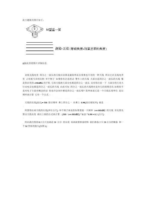
此主题相关图片如下:
按此查看图片详细信息
业馀无线电里四分之一波长的天线应该算是最简单而且效果也不差的一种天线所以它在无线电界里占有相当多的比例举个例子如果你有注意的话警车上的天线大部分是四分之一波长的天线像是你在用的430MHZ的手机它的天线绝大部分也都是四分之一波长还有你注意一下大部分的大哥大行动电话也都是四分之一波长的天线由此可知四分之一波长的天线绝对是有它的效果存在.如果你不是对电子方面有概念的话你也许会问什麽是四分之一波长呢? 简单来说它是一个天线长度单位是以频率来计算它有一个公式: %0
©『中国业余无线电』-- 『中国业余无线电』=uT4
天线的长度(波长)= 300 除以频率乘上四分之一在乘上0.96(波长缩短率) 就是T;..d
©『中国业余无线电』-- 『中国业余无线电』[U*x<&
所算得出来天线的长度(单位公尺) 举个例子来说你如果要做一只频率144.00MHZ的天线首先要先算出天线长度就以上面的公式来计算: (300 / 144.00MHZ) * 0.25 * 0.96 = 0.5 (公尺) ~VF5S
©『中国业余无线电』-- 『中国业余无线电』"t~IJ[
所以我们得到0.5公尺也就是50 公分的长度再来就要准备材料我们准备5只50公分的铜条和一个M型座的接头(如图1) gP。
短波天线的原理和应用实例
短波天线的原理和应用实例1. 短波天线的原理短波天线是无线电通信中常用的天线类型之一,它主要用于接收和发射短波信号。
短波信号属于高频信号,波长范围在10米至100米之间,通常用于远距离通信。
短波天线的工作原理基于电磁感应和辐射原理。
当电磁波通过天线时,它会与天线的导体产生相互作用。
这些作用包括导体中自由电子的运动和天线所产生的辐射场。
短波天线通过合理设计和调整,能够达到良好的接收和发射效果。
短波天线的基本原理可以概括如下: - 天线长度与波长相匹配:短波天线的长度应与所要接收或发射的信号的波长相匹配,以获得更好的谐振效果。
- 地面反射:短波天线通常需要一个接地平面来增强信号的接收和发射效果,这个接地平面一般是地面或者人工建立的接地系统。
- 天线定向性:通过改变短波天线的结构和布局,可以实现方向性辐射,以增强信号的传输和接收效果。
- 天线匹配:为了获得最大的信号传输效率,短波天线需要与发射或接收设备之间进行匹配,以达到合适的阻抗匹配。
2. 短波天线的应用实例短波天线在无线电通信中有着广泛的应用,下面列举几个常见的应用实例:2.1 短波广播接收短波广播是一种特殊的广播方式,它的传播距离远大于FM广播,因此需要专门的设备和天线来接收。
通过连接短波天线,可以接收到来自世界各地的广播电台的信号。
短波广播可以提供国内外的新闻、音乐、文化、天气等丰富的内容,是人们获取全球信息的重要途径。
2.2 短波业余无线电通信业余无线电通信是一种业余爱好,也是无线电技术爱好者之间交流的方式,短波天线在业余无线电通信中起到了至关重要的作用。
无线电爱好者可以通过连接短波天线,与全球的无线电爱好者进行交流,包括语音通信、数据通信、电报等。
2.3 短波无线电定位短波无线电定位是一种利用短波天线接收对方信号强度和方向来确定对方位置的技术。
通过接收到的信号强度和方向信息,可以计算出对方的大致位置。
这种技术在军事、航空、航海等领域有着广泛的应用。
短波天线概述范文

短波天线概述范文短波天线是用于接收和发射短波信号的一种设备。
它是无线电通信系统中的重要组成部分,可以将电磁波转化为电信号,或将电信号转化为电磁波。
短波天线通常用于短波广播、无线电电报、海事通信、航空通信、航海通信以及军事通信等领域。
它的工作频率范围通常在1.8MHz至30MHz之间,而且可以覆盖大范围的地理区域。
短波天线的结构一般由一根或多根导线组成,可以是直立天线、水平天线、对数周期天线、圆环天线等形式。
其中,直立天线是最常见的一种,由一根直立的导体组成,以地面为反射板,可以有效地接收短波信号。
短波天线主要通过改变其长度以适应不同的频率和波段。
一般情况下,天线长度会与信号的半波共振频率相匹配,这样可以最大程度地提高信号的接收效果。
根据天线的长度和形状,可以调整发射电磁波的方向和增益,从而实现不同的通信需求。
短波天线有着广泛的应用,不仅可以用于接收各种类型的短波信号,还可以用于发送通信信号。
它的性能和效果受到多种因素的影响,包括天线的设计和制造质量、天线与地面的接触方式、天线与其他设备的匹配程度等。
短波天线的优点是可以在大范围内进行通信,无需依赖具体的地理位置。
而且短波信号的传播特性使其具备强大的穿透力,可以通过大气层的反射和折射传播到远距离的地区。
这使得短波天线在长距离通信、应急通信等方面具备重要的意义。
然而,短波天线也存在一些局限性。
由于短波信号的传播受到大气状况、天气条件和电离层的影响,使得信号的传输质量不稳定。
此外,由于使用短波天线需要相应的设备和预先设置的工作频率,因此在一些场景下可能存在一定的限制。
总的来说,短波天线是一种非常重要的无线电通信设备,具备广泛的应用领域和通信能力。
虽然存在一些局限性,但随着技术的不断进步和发展,短波天线的性能和效果仍然可以不断得到提高。
随着无线通信技术的不断发展,人们对短波天线的需求也将不断增加,其应用前景将会继续扩大。
短波电台天线操作方法

短波电台天线操作方法
操作短波电台天线的方法如下:
1.调整天线长度:根据要接收或发送的频率选择适当的天线长度。
天线长度可以通过添加或移除天线的节段来调整。
2.选择天线型式:常见的短波天线类型包括偶极子天线、垂直天线和对数周期天线等。
根据实际需求选择合适的天线型式。
3.安装天线:将天线固定在适当高度的支架上。
确保天线垂直且稳固,避免与其他金属物体接触。
4.连接天线:将天线电缆连接到电台的天线接口上。
使用合适的连接器,确保连接牢固无松动。
5.调谐天线:通过调整天线的长度或电容装置来匹配电台的输出阻抗。
调谐天线可以提高电台的性能和传输效果。
6.定期维护:定期检查天线连接是否松动,清除可能的杂物积聚,并检查天线线缆是否损坏。
必要时,进行修复或更换。
需要注意的是,操作天线时应注意安全,避免不必要的触电风险。
在操作之前,
最好查阅相关的天线使用手册或咨询专业人士以获得更详细的指导。
- 1、下载文档前请自行甄别文档内容的完整性,平台不提供额外的编辑、内容补充、找答案等附加服务。
- 2、"仅部分预览"的文档,不可在线预览部分如存在完整性等问题,可反馈申请退款(可完整预览的文档不适用该条件!)。
- 3、如文档侵犯您的权益,请联系客服反馈,我们会尽快为您处理(人工客服工作时间:9:00-18:30)。
PAC-12 Kit ContentsPart QuantityScrews: 8/32 x 3/8” 8Screws: 8-32 x 5/16” 2Screw: 8-32 x 1/4” 1#8 internal tooth washers 8#8 solder lug ring terminals 6Bolt: Aluminum, 1/4-20 x 1.5” 11/4” internal tooth washer 1Nut: Aluminum hex, 1/4-20 1Stainless wing nut, 1/4-20 11/4” ring terminals 3BNC connector 1BNC mounting plate 1Wire, PVC insulated stranded 12”Wire, 18AWG enamel copper 114 conductor ribbon cable roll 1Feedpoint insulator PVC tube 1Feedpoint insulator end caps 26” Coil form, PVC 13.5” Coil form, PVC 1Coil form end caps 4Aluminum Rods 12” 2Aluminum hex coupling nuts 172” telescoping antenna 1Antenna whip adapter 1Aluminum ground spike 1Tools NeededSoldering ironPhillips screwdriverWire stripperWrenches, 7/16” and 1/2”Terminal crimp toolPliersSolderFeed point insulator assemblyParts:PVC base tube (1)Aluminum end caps (2)8-32 x 5/16” Phillips head screws (2)#8 Size solder lugs (2)BNC mounting plate (1)BNC connector (1)Green stranded wire (12”)Stainless wing Nut (1)Start by inserting the 2 smaller aluminum end caps into the ends of the PVC tube. Align the holes and secure using the two 8-32 x 5/16” stainless screws with a solder lug placed under each screw. Be sure to use the correct screws, as the longer 3/8” screws supplied for the loading coil will interfere with the threaded sections screwing into the end caps. The screws should start smoothly and should not require much effort to tighten. If otherwise, make sure the threads are aligned properly. Be careful not to over tighten as the end cap metal is aluminum and is it possible to strip the threads.Using the ¼ -20 x 1.5” bolt, lock washer and nut, attach the BNC mounting plate to the feed point insulator PVC tube by inserting the bolt through the PVC tube and then through the aluminum bnc mounting plate. Secure with a lock washer and the ¼-20 nut. Tighten from the bolt head side while holding the BNC plate in position.Mount the bnc in the plate and secure using its nut. The BNC connectors may be supplied with a red rubber gasket that should be removed before installation.Once the BNC is securely installed, cut small lengths of the insulated stranded wire (green) from the 12” section provided. Tin the ends and solder between the bnc fitting and the solder lugs under each screw. Be sure to sufficiently heat all connections so that the solder flows smoothly and a good physical and electrical bond is formed.Install the stainless wing nut screw onto the end of the 1/4-20 bolt in the center. It is used to secure the ring terminals for connection of the radials.This completes the assembly of the feed point insulator. Check for continuity using an ohmmeter between the center and shell of the BNC and the end caps of the antenna. Resistance readings should be no more than one or two ohms including the meter lead resistance. Also verify that there is no short by checking resistance between the end caps or across the BNC. Resistance should read very large or infinite here.Note that the feed point insulator is symmetric. This feature allows the antenna to be used as a dipole as well as a vertical. When used as a dipole, the bolt in the center serves as the antenna support point for attaching to a mast. When using the antenna as a vertical, make sure to install the feed point insulator with the center conductor of the bnc connected to the antenna and the shell to the radials.Loading coil assemblyParts:PVC coil form, light gray (1)Aluminum end caps (2)8-32 x 3/8” stainless Phillips screws (4)#8 internal tooth lock washers (2)#8 ring solder lugs (2)#18 Enamel insulated copper wireThe loading coils are assembled using the 2 larger end caps, the larger light gray PVC coil form and 4 of the 8-32 x 3/8” screws. Two #8 lock washers and 2 #8 solder lugs are used. The two lock washers go on one side to secure the screws and the 2 solder lugs go on the other side and are used for connecting the coil windings. Insert the end caps, align the screw holes and insert the screws.Theassemblyprocessfortheloading coil end caps and screws.Once the coil form is assembled, it is ready for winding the loading coil. The coil form has a series of holes used to secure the ends of the winding. Depending on which bandyou plan to construct the coil for, you will use different sets of the holes.A B C D D C B AThe coil form tube showing the holes used to secure the ends of the coils. Pairs of holes are labeled with letters that are used in the winding chart below.Band Meters Turns towindHole set(see photo)10 1 or jumper D12 4 D 15 8 D 17 11 D 20 17 D 30 29 C 40 57 B 60 93 AA complete set of coils for 60,40, 30, 20, 17, 15, and 12M.For 10M you can use the 15 or12M coil with the whipcollapsed for tuning or use ashort jumper across any of thelower frequency coils. First, tin the end of the enamel wire by heating with a blob of solder. Feed extra solder in as necessary and you will see the enamel begin to peel off and the solder will coat the bare end. Tin approximately 0.5” of the wire to prepare it for connection at the solder lug later. Determine hole pair from the winding chart and pass the end of the enameled wire through one of the holes so that is passes through the coil form from one side to the other. Pull enough extra wire toloop back through holeset A and to passthrough the hole in thesolder lug on the end ofthe form.This photo setillustrates how the wires are routed through the holes at the ends of the coil. For example, for the 20M coil, pass the end of the wire through the coil form in one of holes labeled D. From the other side of the coil, pull enough wire to lie along the coil form and pass back through the coil through hole set A. Hole set A will be used in this fashion for all coils except the 60M one. In that case, the wires at the end of the coil just pass through hole set A and connect to the solder lugs. In all other cases they form a loop from one side to the other and back again. This helps to strain relief the end connections.Note in the photos of the entire coil sethow the wires pass into the form onone side and along the form on theopposite side to secure the coils. Fromone side you should have the coil endsdisappearing into the coil form andfrom the other, the wires emerge, lie along the coil form and re-enter at hole set A, pass through and connect at the solder lugs. If using the inner hole sets, you can loop the wire back and forth through the unused hole sets to prevent a long run down the coil form on one side.Secure the terminal and fold the wire down to lie flat along theterminal. If you do not wish to permanently connect the coil, youmay rather just loop the wire under the screw and the lug andconnect by tightening. Otherwise, solder the wire to the terminal.You may find it best to remove the terminal while soldering toavoid melting the PVC form.Begin by winding the coil by turning the form while feeding the wire onto it. Using the thumb and forefinger will work to guide the wire. Each time the wire passes around the form and back past the point where it enters the hole in the PVC counts as one turn. Continue winding until the specified number of turns has been applied. If you need to stop during the process, secure the windings using adhesive tape until you are ready to continue. While winding, you may find it necessary to occasionally push the turns together for a tighter coil. On most coils except for 60M, there is extra space and this is not strictly necessary, it just improves the appearance.Once the required number of turns has been applied, cut the wire with approximately 6” extra. Pass the end of the wire through the PVC tube using the adjacent set of holes and then back through the next set. Pull the wire tight during this step to secure the coil. Measure the length of wire to reach the screw and cut it, leaving enough to loop around the screw. Strip the insulation from the end as before and tin with solder. A blob of solder on the tip of the soldering iron will usually remove the insulation and tin the wire.Form the wire around the screw under the terminal but not soldered to it and tighten to secure. This is a temporary connection for testing of the antenna. Once the resonant point is checked, the wire may be soldered to the terminal as was done on the opposite end. Or, if you plan to rewind the coil for another band at some point, just secure both ends of the wire under a screw with a loop as shown in the last photo below.A completed coil. Note thewire routing and one end left unsoldered for testing.Once compete, check the end-to-end resistance of the coil using an ohmmeter. It should be no more than one or two ohms or less for any of the coils. If a resistance value higher than this is noted, recheck the tightness of the screws and that the solder joint and loop make good contact.3.5” Compact Coil Instructions:For winding the Compact coils, use the same technique and winding chart as for the full size 6” coils. There is sufficient space on the form for winding coils for 30M and higher. The coil forms have 4 holes used for securing the ends of the coils during and after winding. See the photos and chart below for information:BandMeters Turns to wind Hole set (see photo)10 1 or jumper B12 4 B15 8 B17 11 B20 17 B30 29AAs with the full size coils, start by passing the end of the wire through the coil and attach a solder lug or strip the wire and loop under the screw at one end of the coil. Wind as withthe full size coils, counting the turns each timeit passes back past the start point. I recommendjust stripping or tinning the other end andlooping it under the screw for testing.Assemble the antenna and test for lowest swr.You may need to collapse up to one full sectionor more of the whip to achiever a low swr at thelow end of the band. The coil turns specifiedabove will put the swr minimum at or near thelow end of each band. To go higher, yousimply collapse the whip. You may need tocollapse up to one full section or more of thewhip to achiever a low swr at the low end of theband. If more than one section is collapsed,remove a turn from the coil and retest. Onceyou are happy with the coil, you can solder theend to a solder lug or just leave it looped underthe screw.Whip assembly.Parts:72” telescoping whip (1)Aluminum whip adapter 1)8-32 x 1/4” Phillips head screw (1)To assemble the whip, slip it into the whip adapter until it hits bottom. If the fit is tight, it may require rotating the whip slightly while inserting. Once in place, secure using the 8-32 x 1/4” Phillips head screw. This completes the whip assembly.Radial Ground coupling systemParts:14-conductor ribbon cable1/4” ring terminalsThe ribbon cable supplied is used to produce aset of short radials. These are intended foroperation when the antenna is ground mountedas an earth coupling system. If the antenna is tobe mounted above ground, a set of at least 3 or 4-quarter wave radials should be used for eachband.Simply separate the 14-conductor ribbon cableinto 2-conductor sections giving a total of 7wires. While you can separate into single wires,I do not recommend this, as the wires aresomewhat fragile alone. Strip the ends of the wires back a half-inch or so, and twist them together. You should be able to put 3 or 4 twisted sets into one ring terminal. Crimp the terminal and use electrical tape or heat shrink tubing to strain relief the connection.Assembling the antennaCautionAs with any antenna, do not use near electrical wires either overhead or buried.Use caution whenever using the ground spike to make sure the area is clear of buried plumbing or electric wires. If in doubt, do not use the ground spike.Also, use caution with the ground spike as the end is sharp and can cause injury. Do not allow children to play with the antenna.AssemblyTo assemble the antenna, gather the parts that have been prepared. In addition to the components that you have already assembled, you will need the 2- 12” aluminum rod sections, coupling nuts and the ground spike (if ground mounting the antenna).If it is available, some aluminum antioxidant grease will make assembly and disassembly of the antenna easier as well as maintain good conductivity between the sections. Small tubes of a suitable material can be found in the electrical sections of most hardware stores where it is sold for use with aluminum house wiring and interconnects.Screw the ground spike into the grounded side (BNC shell) of the feed point adapter. Screw a 12” rod section into the other end. Place a coupling nut on this rod and add the second section of rod. The loading coil screws onto the end of the second rod. Tighten all connections securely but do not over tighten as the threads may be damaged.Connect the whip to the other end of the coil by screwing the adapter into the threaded opening in the coil. This completes assembly of the antenna.For operation, connect the radial wires or counterpoise to the ¼” bolt in the center of the feed point using the supplied wing nut to secure the ring terminals on the radial wires.The antenna will also mount on any standard camera tripod using a 1/4-20 thread.If mounted much above ground, it may be necessary to use resonant radial wires for best performance. The radial kit supplied is intended for close ground mounting and is designed for coupling to the ground under these conditions. When the ground is not present, longer radial wires will improve performance.Thank you for purchasing the PAC-12 antenna kit, please contact us via email if we can help in any way.The latest version of this manual will also be posted on our website.James BennettKA5DVSEmail:support@Website:。