CS8211AEO
罗氏公司校准品
溯源性和标准化一、基本概念(一)溯源性定义:通过一条具有规定不确定度的不间断的比较链,使测量结果或测量标准的值能够与规定的参考标准,通常是与国家标准或国际标准联系起来的特性。
[VIM:1993,定义6.10]临床检验的目的:对患者新鲜标本检验报告可靠的结果。
临床检验的传统:对收集的患者标本只做一次检验,就发出报告。
因此,发出报告的可靠性必须体现两个基本要求:精密度:重复性好;准确度:和参考方法具有可比性。
在临床检验中,公认:在参考实验室内,由具有认可资格的操作人员使用参考方法、或以参考品为标准,对新鲜标本进行的检测结果是参考值结果。
可是,在参考实验室内的所有参考方法是手工方法;或使用参考品校准的方法,在实现参考值的传递上非常烦琐。
在日常检测中,无法使用这样的参考方法或参考品进行大量病人标本的检测,出报告。
因此,现实问题是:是否可以让常规的检测系统,对病人标本的检测,在计量单位一致的前提下,得到和参考系列相同的检测量值。
这就是通过一条不间断的比较链,使检测结果或检测标准的值能够与规定的参考标准,通常是与国家标准或国际标准联系起来。
为此,生产厂商必须对完成检测涉及的检测系统各组分(仪器、试剂、校准品、和操作程序)进行严格的标准化程序,实现溯源性。
(二)标准化1972年,由ISO出版,T.R.B.Sanders主编的《标准化的目的与原理》一书对标准化下的定义是:“标准化是为了所有有关方面的利益,特别是为了促进最佳的、全面的经济并适当考虑到产品使用条件与安全要求,在所有有关方面的协作下,进行有秩序的特定活动所制定并实施各项规则的过程。
”可以简单理解为:为了实现临床检验结果的溯源性,检测系统的生产厂商的所有努力的过程为标准化。
(三)理解检验的特点1.检验的检测对象是病人标本,而且一定是新鲜的标本。
实验室使临床和病人满意的是检验结果的可靠性。
实现结果可靠性的质量管理有许多内容。
在保证收集和处理的标本质量、在检验后不存在处理检测数据和发出报告的差错前提下,获得可靠结果的主要阶段是分析过程的质量。
碘酸铵安全技术说明书msds
如果蒸气浓度超过职业接触限值或发生刺激等症状时,请使用全面罩式多功能防毒面具(US)或AXBEK型(EN 14387)防毒面具筒。
眼睛防护:
佩戴化学护目镜(符合欧盟EN 166或美国NIOSH标准)。
身体防护:
穿阻燃防静电防护服和抗静电的防护靴。
手防护:
戴化学防护手套(例如丁基橡胶手套)。建议选择经过欧盟EN 374、美国US F739或AS/NZS 2161.1标准测试的防护手套。
第七部分操作处置与储存
操作注意事项:
在通风良好处进行操作。穿戴合适的个人防护用具。避免接触皮肤和进入眼睛。远离热源、火花、明火和热表面。采取措施防止静电积累。
储存注意事项:
保持容器密闭。储存在干燥、阴凉和通风处。远离热源、火花、明火和热表面。存储于远离不相容材料和食品容器的地方。
第八部分接触控制/个体防护
食入:
禁止催吐,切勿给失去知觉者从嘴里喂食任何东西。立即呼叫医生或中毒控制中心。
第五部分:消防措施
危险特性:
不燃烧,但会增强火势。与木材、纸张、油类或金属粉末等可燃物质接触,能引起自燃或剧烈分解。因释放氧气有助燃效果。物质含有氧化剂/有机过氧化物,可通过供氧使火势加强并让火焰自身维持。灭火行动对已发生的火灾可能无效。遇火会产生刺激性、毒性或腐蚀性的气体。加热时,容器可能爆炸。暴露于火中的容器可能会通过压力安全阀泄漏出内容物。受热或接触火焰可能会产生膨胀或爆炸性分解。
第十六部分其它信息
参考文献
【1】国际化学品安全规划署:国际化学品安全卡(ICSCs)
【2】国际癌症研究机构
【3】OECD全球化学品信息平台
【4】美国CAMEO化学物质数据库
【5】美国医学图书馆:化学品标识数据库
CS8211AEO

电话:0510-8180 5243
传真:0510-8180 5110
无锡华润华晶微电子有限公司
第6页 共6页
无锡华润华晶微电子有限公司
第2页 共6页
CS8211AEO
○R
VOUT
=
NS NP
⋅ R2 + R3 R2
⋅VFB
− VDiode
当 FB 侦 测 电 压 超 过 V FBM AX ,则 系 统 发 生 过 压 保 护 ,系 统 将 进 入 自 动 重 启 过 程 ,如 果 输 出 过 压 状 态 还 没 有 消 除 , 系 统 将 反 复 不 断 尝 试 性 重 启 ( 打 嗝 模 式 )。
NP NS
× I peak
2.2.3 电流检测和前沿消隐
CS8211AEO 芯片侦测 CS 端到 GND 的采样电阻 RCS 上的电压,每个开关周期,变 压器电感电流从 0A 上升,RCS 电压也从 0V 上升,当 RCS 电阻电压超过 0.6V 后,立刻 关断功率管。这样芯片实现逐周期峰值电流限制,严格控制变压器原边电流大小。
最小
最大
5.05
0.37
0.47
1.27
5.80
6.20
3.85
3.95
1.35
1.45
标注 C1 C2 C3 D1 D2
最小
最大
0.575
0.625
0.575
0.625
0.00
0.20
0.40
0.60
4.85
部件名称
引线框 塑封树脂
芯片 内引线 装片胶
说明
产品中有毒有害物质或元素的名称及含量
有毒有害物质或元素
同 样 ,当 FB 侦 测 电 压 低 于 V FBMIN ,则 系 统 发 生 短 路 保 护 ,系 统 将 进 入 自 动 重 启 过 程 , 如 果 输 出 短 路 状 态 还 没 有 消 除 , 系 统 将 反 复 不 断 尝 试 性 重 启 ( 打 嗝 模 式 )。
Leviton ATLAS-X1 Cat 6A Component-Rated UTP QUICKP

Page 1 of 2APPLICATIONThe ATLAS-X1 Cat 6A Component-Rated UTP QUICKPORT Jack supports 10GBASE-T networks. The jack is part of a complete ATLAS-X1 Cat 6A UTP system, ideal for the most demanding mission-critical network applications. The connector supports emerging technologies and will easily adapt to network trends.SPECIFICATIONThe jack shall meet or exceed the requirements for channel and component-level electrical transmission performance as described in ANSI/TIA-568.2-D (Cat 6A), ISO/IEC11801-1 (Class E A ), and EN 50173-1 (Class E A ). The jack shall be compliant with ANSI/TIA-1096-A, c(UL)us Listed, and be independently verified for electrical transmission performance and power delivery. The jack body shall be made of die-cast zinc and all plastic components shall be made of high-impact, fire-retardant plastic rated UL 94V-0. The jack shall support tool-free termination and re-termination and shall not require a specialized termination tool. The jack wiring shall be universal to accommodate T568A and T568B wiring schemes. The jack shall be available in 13 colors; more than established by the ANSI/TIA-606-C standard. The jack shall be offered in standard and shuttered styles and select jacks shall be supplied with interchangeable icons. The jack shall be compliant with IEEE 802.3 PoE Type 1, 2, 3, 4 (100 watts max).DESIGN CONSIDERATIONS• Use in any QUICKPORT™ housing to support Cat 6A UTP connectivity in surface-mount, flush-mount, or modular furniture outlets and field-configurable panels• Can be used in conjunction with other QUICKPORT snap-in modules for voice/data/video applications over UTP , coax, and fiber• To identify ports, use different colored modules andicons for each application (full selection of ANSI/TIA-606 compatible colors, 13 available)• Robust housing and shutter protects the jack in harsh environmentsATLAS-X1™ Cat 6A Component-Rated UTP QUICKPORT™ Jack6AUJK-xx6, ICONS-ICxFEATURES• Independently tested and guaranteed to exceed all component, permanent link, and channel margins• Patented Retention Force Technology™ (RFT) protects against tine damage and increases system longevity • For Power over Ethernet, RFT maintains contact force between plug and jack, preventing arcing from intermittent disconnects• Unique design supports tool-free termination andre-termination and requires no specialized termination tool • Short jack design supports a wider range of applications (e.g. shallow boxes, enclosures, bend radius, etc.)• Terminates from 26 to 22 AWG solid or stranded conductors for use on various cable types• Robust IDCs can withstand 20 re-termination cycles and jack contacts are tested for 750 plug-mating cycles to ensure system longevity• Available in 13 ANSI/TIA-606-C compatible colors • Tested and approved for use in air-handling spaces (plenum rating) in accordance with UL Standard 2043• Select jacks available with interchangeable icons (voice, data, A/V, blank) for easy ID• Jack with internal shutter protects against dust and debris • Solid metal body dissipates 53% more heat than plastic, minimizing damage from excess heat in PoE applications • Tine geometry prevents arcing damage where plug and jack make contactSTANDARDS & REGULATIONS• ANSI/TIA-568.2-D (Cat 6A)• ISO/IEC 11801-1 (Cat 6A)• EN 50173-1 (Cat 6A)• ANSI/TIA-1096-A (formerly FCC Part 68)• IEC 60603-7 (includes IEC 60512-5-2)• IEC 60512-99-002• IEEE 802.3 PoE Type 1, 2, 3, 4 (100 watts max)• Cisco UPOE, UPOE+ (90 watts max)• Power over HDBaseT™ PoH (95 watts max)• c(UL)us Listed (UL 1863)• UL 2043 Plenum Certified • RoHS 3• ETL verified to meet the IEC 60512-99-002 standard for support of IEEE 802.3 Type 4 PoE (100 watt) applicationsCOUNTRY OF ORIGINUSA and Mexico (Contact Customer Service for details)6AUJK-xx6, ICONS-ICxUSANetwork Solutions Headquarters +1 (800) 722 2082 *******************Leviton Berk-Tek Cable : +1 (800) 237 5835 ************************Asia Pacific+852 3620 2602********************Canada+1 (800) 461 2002**********************Europe+44 (0) 1592 772124 **********************Latin AmericaMX: +52 (55) 2128 6286 LATAM: +52 (55) 2333 5963 *********************Middle East & Africa +971 (4) 247 9800 *******************NETWORK SOLUTIONS PRODUCTS ARE AVAILABLE WORLDWIDE IN OVER 100 COUNTRIES. VISIT US ONLINE AT /NS TO LEARN MORE.Page 2 of 2For further support information, visit /ns/support6AUJK-xx6, ICONS-ICx6AUJK-xx6, ICONS-ICxMECHANICAL SPECIFICATIONSDimensions:See belowMaterials: Jack Body: Die-cast zincSpring-Wire Contacts: High quality, copper-based alloy, plated with 50 microinches of gold for lowest contact resistance andmaximum life Temp. (Storage):Temp. (Installation): Temp. (Operating):Humidity (Max.):WARRANTY INFORMATIONFor Leviton product warranties, go to /ns/warrantyPART NUMBERDescriptionStandard Jack Jack with Shutter GREENPACK™12-Pack Standard Jack ATLAS-X1™ Cat 6A Component-Rated UTP QUICKPORT™ Jack, white 6AUJK-RW66AUJK-SW66AUJK-CW6ATLAS-X1 Cat 6A Component-Rated UTP QUICKPORT Jack, light almond 6AUJK-RT66AUJK-ST6—ATLAS-X1 Cat 6A Component-Rated UTP QUICKPORT Jack, ivory 6AUJK-RI66AUJK-SI6—ATLAS-X1 Cat 6A Component-Rated UTP QUICKPORT Jack, yellow 6AUJK-RY66AUJK-SY6—ATLAS-X1 Cat 6A Component-Rated UTP QUICKPORT Jack, orange 6AUJK-RO66AUJK-SO6—ATLAS-X1 Cat 6A Component-Rated UTP QUICKPORT Jack, crimson 6AUJK-RC66AUJK-SC6—ATLAS-X1 Cat 6A Component-Rated UTP QUICKPORT Jack, dark red 6AUJK-RR66AUJK-SR6—ATLAS-X1 Cat 6A Component-Rated UTP QUICKPORT Jack, purple 6AUJK-RP66AUJK-SP6—ATLAS-X1 Cat 6A Component-Rated UTP QUICKPORT Jack, blue 6AUJK-RL66AUJK-SL66AUJK-CL6ATLAS-X1 Cat 6A Component-Rated UTP QUICKPORT Jack, green 6AUJK-RV66AUJK-SV6—ATLAS-X1 Cat 6A Component-Rated UTP QUICKPORT Jack, gray 6AUJK-RG66AUJK-SG6—ATLAS-X1 Cat 6A Component-Rated UTP QUICKPORT Jack, black6AUJK-RE66AUJK-SE66AUJK-CE6ATLAS-X1 Cat 6A Component-Rated UTP QUICKPORT Jack, brown6AUJK-RB66AUJK-SB6—Green (V)Blue (L)Purple (P)Crimson (C)Dark Red (R)Orange (O)Yellow (Y)Black (E)Gray (G)Ivory (I)Light Almond (T)Brown (B)Color-matched icons (ICONS-ICx) can be ordered separately in 72-quantity packs.x = icon color。
TPV 8211-35

Santoprene™ 8211-35Thermoplastic Vulcanizate产品说明关键特性它是热塑性弹性体(TPE )• 非吸湿性产品,加工之前很少或不需要干燥。
-中性、易于着色的配方。
- 优异的耐臭氧性能。
- 用于密封应用中。
- 推荐用于要求优异耐挠曲疲劳性能的用途。
-尽管此产品未经 NSF 认证,但是它已经在 NSF系列中的一种软质、可着色、非吸湿性热塑性硫化弹性体(TPV ) 。
这种材料同时具有良好的物理性质和耐化学性, 用于较难注塑成型的领域。
这一牌号的山都平 TPV 是剪切速率依赖型产品,备案了一份《材料提供商申请表》,可在常规热塑性注塑成型设备上加工。
它是聚烯烃基产品, 可以完全回收利用。
这可以方便评估此产品能否用于需要 NSF 认证的应用中。
- 符合 RoHS 规范。
总体 供货地区 1 • 北美洲 • 非洲和中东• 拉丁美洲 • 南美洲 • 欧洲 • 亚太地区 应用• 密封件和垫片• 汽车 - HVAC 挡板门密封条 • 汽车 - 把套 • 汽车 - 车内脚垫 • 汽车 - 密封条 • 汽车 - 内饰 • 软质手柄 • 消费品应用 用途 • 密封• 汽车领域的应用: • 柔软的把手 • 手机• 消费品应用领域机构评级 RoHS 合规性 汽车要求 外观 • EU Annex XVII of Regulation (EC) No 1907/2006 • RoHS 合规• CHRYSLER MS-AR100 AMN • GM GMP.E/P.083 • 自然色• 颗粒料 形式 加工方法 修订信息 • 多次注射成型 • 01/22/2013• 注射成型物理性能 比重 典型数值 (英制 ) 典型数值 (公制 ) 测试依据 0.930 0.930 ASTM D792ISO 1183 密度 0.930 g/cm³ 0.930 g/cm³ 硬度 典型数值 (英制 )38典型数值 (公制 )38测试依据 ISO 868支撐硬度邵氏 A, 15 秒, 73°F (23°C), 0.0787 in (2.00 mm) 弹性体典型数值 (英制 )145 psi 典型数值 (公制 )1.00 MPa 测试依据 拉伸应力(在100%时) - 横向流量 (73°F (23°C)) ASTM D412 拉伸应力(在100%时) - 横向流量 (73°F (23°C)) 145 psi 1.00 MPa ISO 37 拉伸断裂强度 - 横向流量 (73°F (23°C)) 拉伸断裂应力 - 横向流量 (73°F (23°C)) 421 psi 421 psi 350 %2.90 MPa 2.90 MPa 350 % ASTM D412 ISO 37 伸长率(在断裂伸长时) - 横向流量 (73°F (23°C)) ASTM D412 拉伸断裂应变 - 横向流量 (73°F (23°C))350 %350 %ISO 37弹性体典型数值 (英制 ) 典型数值 (公制 ) 测试依据压缩永久变形ASTM D395B73°F (23°C), 22.0 hr, 类型 1 257°F (125°C), 70.0 hr, 类型 1 压缩永久变形10 %36 %10 %36 %ISO 81573°F (23°C), 22.0 hr, 类型 A 257°F (125°C), 70.0 hr, 类型 A 10 %36 %10 %36 %热性能典型数值 (英制 )-85 °F 典型数值 (公制 )-65 °C测试依据ASTM D746ISO 812脆化温度脆化温度-85 °F -65 °C注射典型数值 (英制 )0.080 % 典型数值 (公制 )0.080 %建议的最大水分含量建议的最大回制料比例20 % 20 %螺筒后部温度螺筒中部温度螺筒前部温度射嘴温度350 到 375 °F355 到 380 °F365 到 390 °F365 到 410 °F290 到 420 °F75.0 到 125 °F快速177 到 191 °C179 到 193 °C185 到 199 °C185 到 210 °C143 到 216 °C23.9 到 51.7 °C快速加工(熔体)温度模具温度注射速度背压50.0 到 100 psi100 到 200 rpm3.0 到 5.0 tons/in²0.125 到 0.250 in 0.345 到 0.689 MPa100 到 200 rpm41 到 69 MPa 3.18 到 6.35 mm螺杆转速合模力垫层螺杆长径比16.0:1.0 至20.0:1.0 16.0:1.0 至20.0:1.0螺杆压缩比排气孔深度2.0:1.0 至 2.5:1.00.0010 in2.0:1.0 至 2.5:1.00.025 mm注射说明Santoprene TPV与乙缩醛和PVC不相容。
SpicaTM Gen2 PAM4 DSP for 800G Optical Module Appl
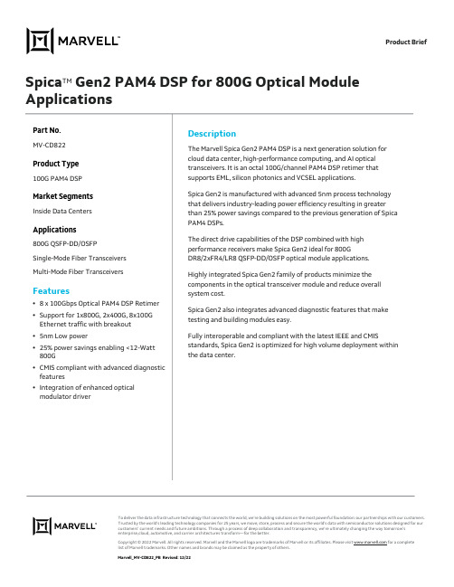
Product Brief Spica TM Gen2 PAM4 DSP for 800G Optical Module ApplicationsPart No.MV-CD822Product Type100G PAM4 DSPMarket SegmentsInside Data CentersApplications800G QSFP-DD/OSFPSingle-Mode Fiber TransceiversMulti-Mode Fiber TransceiversFeatures•8 x 100Gbps Optical PAM4 DSP Retimer •Support for 1x800G, 2x400G, 8x100G Ethernet traffic with breakout•5nm Low power•25% power savings enabling <12-Watt 800G•CMIS compliant with advanced diagnostic features•Integration of enhanced optical modulator driver DescriptionThe Marvell Spica Gen2 PAM4 DSP is a next generation solution for cloud data center, high-performance computing, and AI optical transceivers. It is an octal 100G/channel PAM4 DSP retimer that supports EML, silicon photonics and VCSEL applications.Spica Gen2 is manufactured with advanced 5nm process technology that delivers industry-leading power efficiency resulting in greater than 25% power savings compared to the previous generation of Spica PAM4 DSPs.The direct drive capabilities of the DSP combined with high performance receivers make Spica Gen2 ideal for 800GDR8/2xFR4/LR8 QSFP-DD/OSFP optical module applications.Highly integrated Spica Gen2 family of products minimize the components in the optical transceiver module and reduce overall system cost.Spica Gen2 also integrates advanced diagnostic features that make testing and building modules easy.Fully interoperable and compliant with the latest IEEE and CMIS standards, Spica Gen2 is optimized for high volume deployment within the data center.To deliver the data infrastructure technology that connects the world, we’re building solutions on the most powerful foundation: our partnerships with our customers. Trusted by the world’s leading technology companies for 25 years, we move, store, process and secure the world’s data with semiconductor solutions designed for our customers’ current needs and future ambitions. Through a process of deep collaboration and transparency, we’re ultimately changing the way tomorrow’s enterprise, c loud, automotive, and carrier architectures transform—for the better.Copyright © 2022 Marvell. All rights reserved. Marvell and the Marvell logo are trademarks of Marvell or its affiliates. Please visit for a completelist of Marvell trademarks. Other names and brands may be claimed as the property of others.Marvell_MV-CD822_PB Revised: 12/22。
Hoffman Enclosures Inc. 电子变压器操作适配器(适用于Eaton Cutle
89115496
© 2018 Hoffman Enclosures Inc.
PH 763 422 2211 • /HOFFMAN
-3-
For Floor-Mounted, Two-Door Enclosures with Disconnect on Right Flange
0DVWHU 'RRU
)RURQHWKURXJKVL[GRRUIUHHVWDQGLQJHQFORVXUHV ZLWKWKHGLVFRQQHFWWKHWKHULJKWIODQJH 0DVWHU 'RRU
)RUIORRUPRXQWHGHQFORVXUHVZLWK WKHGLVFRQQHFWRQWKHFHQWHUSRVW
Step 5 Attach the bottom of the slide arm (item 4) to the offset arm of the lock release mechanism. Use two flat washers (item 8), two lockwashers (item 9), and two hex nuts (item 10). Do not tighten until parts are adjusted (see step 6B)
Item No. Description
Part No.
Qty.
1
MOUNTING PLATE, C-H C361 AND C371
26385001
1
2
GASKET, PLATE
89109613
1
3
SCREW, 1/4-20X1/2 PAN HEAD
99401031
4
4
船舶电气设备船级社认证(CCS认证)
DryHeatTest
GD22-2015
IEC60945
IEC60068-2-2
低温试验
LowTemperatureTest
GD22-2015
IEC60945
IEC60068-2-1
交变湿热试验
DampHeatTest(Cyclic)
GD22-2015
IEC60068-2-30
恒定湿热试验
认可试验范围:ItemsofTestApproved
1电气电子产品ElectricalandElectrionicProducts;
1.1性能检测PerformanceTest
1.2环境试验EnvironmentTest
1.3电磁兼容EMCTest
2无石棉检测Asbestos-freeTest
主要测试标准:
低频传导抗扰度
ImmunitytoConductedLowFrequencyInterference
GD22-2015
射频场感应的传导骚扰抗扰度
ImmunitytoConductedDisturbancesInducedbyRadio-frequencyFields
GD22-2015
IEC60945
DampHeatTest(SteadyState)
GD01-2006
IEC60068-2-3
盐雾试验Kb
SaltMistTestKb
GD22-2015
IEC60068-2-52
盐雾试验Ka
SaltMistTestKa
GD22-2015
IEC60068-2-11
热冲击试验
ThermalShockTest
GD22-2015《电气电子产品型式认可试验指南》是中国船级社(CCS)关于船用电子产品(控制类、内部通信类、计算机及其外设类、低压电气类、电子设备类、电子电气附件、灯具类)的技术规范要求综述。GD22与BV(法国船级社)LR(英国船级社)对于电气电子产品的规定很接近。指南中对安全、环境、EMC测试项目进行了详细描述。
E+H 电极选型
8
Endress+Hauser
Orbisint CPS11/CPS11D
附件
安装支架 Cleanfit W CPA450 手动操作,pH/redox 电极用的可伸缩支架,用于把 120 mm 电极安装在储罐和管道 定货根据产品结构,见技术说明书(TI 183C/07/en,定货号:50090677) (要保证定购的电极内管正确) Cleanfit P CPA471 一体化的可伸缩不锈钢安装支架,储罐和管道安装,手动或气动操作 定货根据产品结构,见技术说明书(TI 217C/07/en,定货号:51502596) Cleanfit P CPA472 一体化可伸缩塑料安装支架,储罐和管道安装,手动或气动操作 定货根据产品结构,见技术说明书(TI 223C/07/en,定货号:51502645) Cleanfit P CPA473 可伸缩不锈钢过程支架,带球阀,特别安全,介质能与周围环境可靠分开 定货根据产品结构,见技术说明书(TI 344C/07/en,定货号:51510923) Cleanfit P CPA474 可伸缩塑料安装支架,带球阀,特别安全,介质能与周围环境可靠分开 定货根据产品结构,见技术说明书(TI 345C/07/en,定货号:51510925)
1998orbisintcps11cps11dendresshauser定货信息产品结构cps11电极类型无温度传感器内置pt100不可与gsa插头一起使用内置pt1000不可与gsa插头一起使用应用范围aabafaph87psiph135c可消毒6barph70c抗氟化氯最大含量120mm225mm360mm425mm插头esagsa插头pg135top6816barex插头pg135din同轴nonexcps11完整的定货码产品结构cps11d结构max135c内置温度传感器应用范围aabafaphbarph135c可消毒6barph70c抗氟化氯最大含量120mm225mm360mm425mm选项标准cps11d完整的定货码orbisintcps11cps11dendresshauser附件安装支架cpa450手动操作phredox电极用的可伸缩支架用于把120mm电极安装在储罐和管道定货根据产品结构见技术说明书ti183c07en定货号
ATEX、CSA c us和IECEx证明的传感器说明书
DatasheetFor use in hazardous areas with suitable zener barriers or galvanic isolatorsATEX, CSA c/us, and IECExFully sealed and rated to IEC IP67/IP69K per DIN 40050-91-, 2-, or 3-color models available with 5 available colorsWARNING: Not To Be Used for Personnel ProtectionNever use this device as a sensing device for personnel protection. Doing so could lead to serious injury or death. This device does not include the self-checking redundant circuitry necessary to allow its use inpersonnel safety applications. A sensor failure or malfunction can cause either an energized or de-energized sensor output condition.ModelsR = Red Y = Yellow B = Blue W = White X = Not UsedColor2Input Q = Integral 4-pin M12/Euro-style Quick Disconnect*QP = 150 mm (5.9 in) cable with4-pin M12/Euro-style Quick Disconnect W/XX = XX ft. Integral PVC Cable13*Models with a quick disconnect require a mating cordsetK50LK30L Models K50L Modelssuffix "Q" with "QP" in the model number. For example, K50LIGXXPQP. Models with a quick disconnect require a mating cordset.K30L and K50L Intrinsically Safe IndicatorsOriginal Document 172445 Rev. D22 September 2020172445Wiring Diagram+_Wiring Key 1 = Brown 2 = White 3 = Blue 4 = Black Color Key C1 = Color 1C2 = Color 2C3 = Color 3PinoutSee Configuration section for hazardous area wiring and installation notes.Configuration_66nF 0.56µF 1.82µF 35µH140µH280µHOne Color ConfigurationNon-Hazardous Location Hazardous Location I.S. Barrier Installation Notes1. Safety parameters are as follows:Ui/Vmax = 30V Ii/Imax = 1APi = 3.4W (Ta = -40 ˚C to +40 ˚C)Pi = 2.8W (Ta = -40 ˚C to +50 ˚C)Ci = 0Li = 02. Choose approved barriers such that the following conditions are met with all barriers combinedUi / Vmax ≥ Uo / Voc Ii / Imax ≥ Io / Isc Pi / Pmax ≥ PoCo / Ca ≥ Ci + Ccable Lo /La ≥ Li + Lcable3. Install I.S. barriers inaccordance with manufacturers instructions and local codes4. Suggested I.S. barriers are as follows MTL 7715+ (15V/100Ω)MTL 7715P+ (15V/50 Ω)Turck MZB15PX (15V/50 Ω)Ccable LcableIICIIBIIAFigure 1. Control Drawing 1-Color Configuration - Tel: + 1 888 373 6767P/N 172445 Rev. D66nF 0.56µF 1.82µF 35µH140µH280µH_Two Color ConfigurationI.S. Barrier Installation NotesK30/K50Flying Lead or Quick Disconnect Models1. Safety Parameters are as follows:Ui / Vmax = 30V Ii / Imax = 1APi = 3.4W (Ta = -40˚C to +40˚C)Pi = 2.8W (Ta = -40˚C to +50˚C)Ci = 0Li = 02. Choose approved barriers such that the following conditions are met with all barriers combinedUi / Vmax ≥ Uo / Voc Ii / Imax ≥ Io / Isc Pi / Pmax ≥ PoCo / Ca ≥ Ci + Ccable Lo /La ≥ Li + Lcable3. Install I.S. barriers inaccordance with manufacturers instructions and local codes4. Suggested I.S. barriers are as follows MTL 7715+ (15V/100Ω)MTL 7715P+ (15V/50 Ω)Turck MZB15PX (15V/50 Ω)IIAIIBIICCcable LcableFigure 2. Control Drawing 2-Color Configuration_66nF 0.56µF 1.82µF 35µH140µH280µHThree Color ConfigurationK30/K50Flying Lead or Quick Disconnect Models1. Safety Parameters are as follows:Ui / Vmax = 30V Ii / Imax = 1APi = 3.4W (Ta = -40˚C to +40˚C)Pi = 2.8W (Ta = -40˚C to +50˚C)Ci = 0Li = 02. Choose approved barriers such that the following conditions are met with all barriers combinedUi / Vmax ≥ Uo / Voc Ii / Imax ≥ Io / Isc Pi / Pmax ≥ PoCo / Ca ≥ Ci + Ccable Lo /La ≥ Li + Lcable3. Install I.S. barriers inaccordance with manufacturers instructions and local codes4. Suggested I.S. barriers are as follows MTL 7715+ (15V/100Ω)MTL 7715P+ (15V/50 Ω)Turck MZB15PX (15V/50 Ω)IIAIIBIICCcable LcableFigure 3. Control Drawing 3-Color ConfigurationGeneral Notes and Conditions for Safe Use1.The dust rating of enclosures/panels may be invalidated by the installation of the EZ-LIGHT(s). The installation of the EZ-LIGHT(s) in a particular enclosure/panel is subject to the evaluation/acceptance of the applicable approval agency.P/N 172445 Rev. D - Tel: + 1 888 373 676732.The user has the responsibility to ensure that all local, state, and national laws, rules, codes, or regulations relating to theinstallation and use of this Banner device in any particular application are satisfied. This Banner device must be installed by Qualified Persons2, in accordance with this document and applicable regulations.3.Do not attempt any repairs to this Banner device; it contains no field-replaceable parts or components.4.The nonconducting materials of this device may be susceptible to ignition-capable level of electrostatic charging andprecautions must be taken to avoid this. The user/installer shall ensure that the equipment is not installed in a locationwhere it may be subjected to external conditions (such as high-pressure steam) which are conducive to creating a build-up of electrostatic charges.5.If the equipment is likely to come into contact with aggressive substances3, then it is the responsibility of the user to takesuitable precautions4 that prevent it from being adversely affected, thus ensuring that the type of protection is notcompromised.6.Clean with a damp cloth only.7.For indicators with multiple colors, only one color is intended to be on at a time.8.When more than one intrinsically safe supply (e.g. two or three barriers) is connected to an LED indicator (input) thecombined electrical parameters of the supply must remain intrinsically safe.SpecificationsSupply Voltage and CurrentSee Configuration for safety parametersIndicatorsEntire translucent diffuser or dome provides indication. LEDs areindependently selected: Green, Red, or Amber; 2 or 3 colors, depending on model. For other colors/combinations, contact Banner Engineering foravailability.Environmental RatingIEC IP67/IEC IP69KApprovalsCSA-c/usGas and Vapors: Class I Zone 0 AEx/Ex ia IIC T4 Ga / Class I Div 1 Groups ABCDDust: Class II Zone 20 AEx/Ex ia IIIC T130°C Da / Class II Div 1 Groups EFG, Class III Div 1CSA 14.2679646ATEX/IECExGas and Vapors: II 1 G Ex ia IIC T4 Ga (Group IIC Zone 0)Dust: II 1 D Ex ia IIIC T130°C Da (Group IIIC Zone 20)Mines: I M1 Ex ia I Ma (Methane)Sira 13ATEX2058XIECEx Sir 13.0020X ConstructionBase: polycarbonateTranslucent dome: polycarbonateConnectionsMaximum cable length 29 m per parameters list in Figure 1 on p. 2, Figure 2 on p. 3, and Figure 3 on p. 3.K30: 2 m (6.5 ft) PVC integral cable, or 150 mm (5.9 in) PVC cable with 4-pin M12/Euro quick disconnectK50: 4-pin M12/Euro integral quick disconnect, 2 m (6.5 ft) PVC integral cable, or 150 mm (5.9 in) PVC cable with 4-pin M12/Euro quick disconnect Operating ConditionsPi = 2.8W: Ta = –40 °C to +50 °C (–40 °F to +122 °F)Pi = 3.4W: Ta = –40 °C to +40 °C (–40 °F to +104 °F)See figures 1, 2, and 3Certifications2809IEC IECEx SIR 13.0020XATEX Sira 13ATEX2058XCSA CoC 2679646certification of professional training, or who, by extensive knowledge, training and experience, has successfully demonstrated the ability to solve problems relating to the subject matter and work.3Aggressive substances—for example, acidic liquids or gases that may attack metals, or solvents that may affect polymeric materials.4Suitable precaution—for example, regular checks as part of routine inspections or establishing from the materials data sheet that it is resistant to specific chemicals. - Tel: + 1 888 373 6767P/N 172445 Rev. DDimensionsK30L Cabled ModelsK50L Quick Disconnect ModelsM30 x 1.5(mounting nutincluded) Max. Torque 4.5 Nm(40 in-lbf)K50L Cabled ModelsAccessoriesCordsetsP/N 172445 Rev. D - Tel: + 1 888 373 67675Banner Engineering Corp. Limited WarrantyBanner Engineering Corp. warrants its products to be free from defects in material and workmanship for one year following the date of shipment. Banner Engineering Corp. will repair or replace, free of charge, any product of its manufacture which, at the time it is returned to the factory, is found to have been defective during the warranty period. This warranty does not cover damage or liability for misuse, abuse, or the improper application or installation of the Banner product.THIS LIMITED WARRANTY IS EXCLUSIVE AND IN LIEU OF ALL OTHER WARRANTIES WHETHER EXPRESS OR IMPLIED (INCLUDING, WITHOUT LIMITATION, ANY WARRANTY OF MERCHANTABILITY OR FITNESS FOR A PARTICULAR PURPOSE), AND WHETHER ARISING UNDER COURSE OF PERFORMANCE, COURSE OF DEALING OR TRADE USAGE. This Warranty is exclusive and limited to repair or, at the discretion of Banner Engineering Corp., replacement. IN NO EVENT SHALL BANNER ENGINEERING CORP. BE LIABLE TO BUYER OR ANY OTHER PERSON OR ENTITY FOR ANY EXTRA COSTS, EXPENSES, LOSSES, LOSS OF PROFITS, OR ANY INCIDENTAL, CONSEQUENTIAL OR SPECIAL DAMAGES RESULTING FROM ANY PRODUCT DEFECT OR FROM THE USE OR INABILITY TO USE THE PRODUCT, WHETHER ARISING IN CONTRACT OR WARRANTY, STATUTE, TORT, STRICT LIABILITY, NEGLIGENCE, OR OTHERWISE.Banner Engineering Corp. reserves the right to change, modify or improve the design of the product without assuming any obligations or liabilities relating to any product previously manufactured by Banner Engineering Corp. Any misuse, abuse, or improper application or installation of this product or use of the product for personal protection applications when the product is identified as not intended for such purposes will void the product warranty. Any modifications to this product without prior express approval by Banner Engineering Corp will void the product warranties. All specifications published in this document are subject to change; Banner reserves the right to modify product specifications or update documentation at any time. Specifications and product information in English supersede that which is provided in any other language. For the most recent version of any documentation, refer to: .For patent information, see /patents.© Banner Engineering Corp. All rights reserved。
- 1、下载文档前请自行甄别文档内容的完整性,平台不提供额外的编辑、内容补充、找答案等附加服务。
- 2、"仅部分预览"的文档,不可在线预览部分如存在完整性等问题,可反馈申请退款(可完整预览的文档不适用该条件!)。
- 3、如文档侵犯您的权益,请联系客服反馈,我们会尽快为您处理(人工客服工作时间:9:00-18:30)。
AND2
消隐 电流采样比较器
CS
VPEAK GND
无锡华润华晶微电子有限公司
第1页 共6页
CS8211AEO
○R
2. 2 功能描述
2.2.1 启动与自动重启
CS8211AEO芯片内部集成 700V高压启动电路,省掉芯片外围启动电阻, 以及辅助 绕组供电电路。当芯片上电时,变压器原边线圈初始电流为 0A,芯片DRAIN端到GND 加AC整流后的高压直流电压,VCC到GND的旁路电容初始电压为 0V,芯片内部的 700V 高压电流源给旁路电容充电,当旁路电容电压上升到 6V时,芯片开始工作。内部电路实 时侦测VCC电压,控制高压电流源的开关实现VCC电压一直稳定在 6V。当系统发生过压、 短路和最小退磁保护时,芯片内部电路强制关断高压电流源开关,由于芯片电路仍然在 消耗电流,旁路电容放电,VCC电压下降。当VCC电压下降到低于 3.4V后,芯片内部所 有电路状态复位,高压电流源开启,VCC电压上升,系统重新启动。
I peak
=
VCS RCS
为了消除功率开关管在开启瞬间产生的尖峰造成的干扰,芯片内置前沿消隐电路, 避免芯片在功率管开启瞬间 CS 端采样电路产生误动作,这样就可以省去 CS 管脚外围 RC 滤除尖脉冲电路,节约系统成本。 2.2.4 保护控制
CS8211AEO 提供输出过压、短路保护和最小退磁时间保护。 系统反激时刻,侦测 FB 端电压,FB 电压与输出电压关系由以下公式来决定:
第4页 共6页
CS8211AEO
○R
4 典型应用线路与应用说明
隔离 Fly-back 方案 注释:在变压器漏感控制在±5%以内时,可省掉 D3、R4、C5 组成的吸收电路。
5 封装尺寸与外形图(单位:mm)
5. 1 外形图
无锡华润华晶微电子有限公司
第5页 共6页
CS8211AEO
○R
5. 2 封装尺寸 标注 A A1 A2 B B1 C
无锡华润华晶微电子有限公司
第2页 共6页
CS8211AEO
○R
VOUT
=
NS NP
⋅ R2 + R3 R2
⋅VFB
− VDiode
当 FB 侦 测 电 压 超 过 V FBM AX ,则 系 统 发 生 过 压 保 护 ,系 统 将 进 入 自 动 重 启 过 程 ,如 果 输 出 过 压 状 态 还 没 有 消 除 , 系 统 将 反 复 不 断 尝 试 性 重 启 ( 打 嗝 模 式 )。
注意
建议您在使用华晶产品之前仔细阅读本资料。 希望您经常和华晶有关部门进行联系,索取最新资料,因为华晶产品在不断更新和提高。 本资料中的信息如有变化,恕不另行通知。 本资料仅供参考,华晶不承担任何由此而引起的损失。 华晶不承担任何在使用过程中引起的侵犯第三方专利或其它权利的责任。
联络方式
无锡华润华晶微电子有限公司
1
CS
口,接采样电阻到芯片 I/O
地。
2
FB
输出电压反馈端口
I/O
3
NC
不连接
芯片内部供电电压端
4
VCC
口
I/O
结构原理图
无锡华润华晶微电子有限公司
第3页 共6页
CS8211AEO
○R
5、6
GND
芯片地
I/O
7、8 DRAIN 功率开关管漏端
I/O
3 电特性
3. 1 极限参数
除非另有规定,Tamb= 25℃
2 功能框图与引脚说明
2. 1 功能框图
VCC
基准偏置
过压侦测 短路侦测
调整器 6V
4.5V VCC重启复位 3.4V
保护逻辑
5.9V VCC欠压保护 4.8V
RQ
RS_NOR
S
Lock ON
DRAIN
最小5.5us 退磁保护
采样时间 4.5us
DEM CSP
恒流控制
AND2
FB
过零比较器
退磁逻辑
Vth
BVDS
VCC=6V VCC=0V,DRAIN=20V V CC =5 .5 V,DRAIN=2 0 V
临界导通模式
250 6 2.4 1.2
610 450 278 4.1 5.5 42.8 30
730
欠压保护
VCC_UVLO
4.8
单位
μA V mA mA mV ns mV V μs % Ω
V
V
无锡华润华晶微电子有限公司
Iout _ avg
=
1× 2
NP NS
× Tdem Tsw
× I peak
只要使得Tdem/Tsw为恒定常数,那么系统输出平均电流就与输入电压及输出电压无 关,仅与峰值电流点、变压器匝数比有关。芯片内部恒流控制电路设定Tdem/Tsw=0.57, 得到系统输出电流公式为:
Iout _ avg
=
0.286 ×
● 低成本的 Buck-Boost 拓扑结构 ● 采用 700V 单芯片集成工艺 ● 85Vac~265 Vac 输入电压范围内实现小于±5%的恒流精度 ● 全电压范围内兼容 1~3W ● 系统无需光耦、TL431 及辅助绕组 ● 内置前沿消隐电路(LEB) ● 逐周期峰值电流比较控制模式 ● 具有输出开/短路保护 ● 封装形式:SOP8
同 样 ,当 FB 侦 测 电 压 低 于 V FBMIN ,则 系 统 发 生 短 路 保 护 ,系 统 将 进 入 自 动 重 启 过 程 , 如 果 输 出 短 路 状 态 还 没 有 消 除 , 系 统 将 反 复 不 断 尝 试 性 重 启 ( 打 嗝 模 式 )。
系统设定变压器电感量LP过小、Ipeak过小(RCS电阻过大)及输出负载电压VOUT过 高的条件下,会造成退磁时间过短,系统频率过高,这时通过侦测退磁时间来提供系统 保护,防止系统振荡频率过高。
NP NS
× I peak
2.2.3 电流检测和前沿消隐
CS8211AEO 芯片侦测 CS 端到 GND 的采样电阻 RCS 上的电压,每个开关周期,变 压器电感电流从 0A 上升,RCS 电压也从 0V 上升,当 RCS 电阻电压超过 0.6V 后,立刻 关断功率管。这样芯片实现逐周期峰值电流限制,严格控制变压器原边电流大小。
公司地址
市场营销部 应用服务
中国江苏无锡市梁溪路 14 号
邮编:214061
网址: http://www.
电话:0510-8580 7228
传真:0510-8580 0864
邮编:214061
电话:0510-8180 5277 / 8180 5336
E-mail: sales@ . 传真:0510-8580 0360 / 8580 3016
3. 2 电特性 除非另有规定,Tamb= 25℃,VCC= 6V
参数名称
符号
测试条件
规范值 最小 典型 最大
静态电流 内部供电电压 高压启动电流 1 高压启动电流 2 电流检测阈值 前沿消隐时间 FB 最小阈值 FB 过压阈值 最小消磁时间 最大占空比 功率管导通电阻 DRAI 端 击穿电压
ICC VCC Ijfet1 Ijfet2 VCS TLED VFBMIN VFBMAX TDEM_MIN DMAX RDSON
Tdem
=
NP NS
LP
× I ode )
当退磁时间Tdem小于 5.5μs时,系统将进入自动重启过程,如果退磁时间被侦测到仍 然小于 5.5μs,系统将反复不断尝试性重启(打嗝模式)。
2. 3 引脚排列图
2. 4、引脚说明与结构原理图 引脚 符 号
功能
属性
原边峰值电流检测端
电话:0510-8180 5243
传真:0510-8180 5110
无锡华润华晶微电子有限公司
第6页 共6页
参数名称
符号
芯片工作电压
VCC
FB 输入电压
VFB
CS 输入电压
VCS
工作温度
TA
存储温度
Tstg
人体放电模式 热阻
VDS 耐压
VESD RΦjA VDS
额定值 -0.3~6 -0.3~6 -0.3~6 -40~+85 -65~+150
4
65 -0.3~730
单位 V V V ℃ ℃ kV
℃/W V
CS8211AEO
○R
单芯片 LED 照明恒流驱动电路
1 概述
CS8211AEO 是一款应用于 LED 照明的单芯片恒流原边控制功率开关电路,在全电 压输入范围内实现恒流输出,恒流精度小于±5%。在原边反馈控制下,系统节省光耦, TL431 以及变压器辅助绕组等元件,降低成本。电路工作在断续导通模式下,具有逐周 期峰值电流限制,FB 过压保护,输出开/短路保护等保护功能,以提高系统的可靠性。 其特点如下:
铅 (Pb)
汞(Hg)
镉(Cd)
六价铬 (Cr+6)
多溴联苯 多溴联苯醚 (PBB) (PBDE)
○
○
○
○
○
○
○
○
○
○
○
○
○
○
○
○
○
○
○
○
○
○
○
○
○
○
○
○
○
○
○:表示该有毒有害物质的含量在 SJ/T11363-2006 标准的限量要求以下。
×:表示该有毒有害物质的含量超出 SJ/T11363-2006 标准的限量要求。
2.2.2 工作原理
CS8211AEO 芯片要实现恒流输出,必需使系统工作在断续导通模式(DCM)下。 芯片通过检测系统的反激退磁时间来控制输出电流恒定。输出电流仅由变压器的匝比及 峰值电流采样电压来控制。