烟台宜科ECS-FT电芬顿技术
Tektronix 2450-EC电化学实验室系统说明书

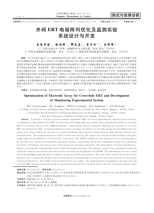
S M U I N S T R U M E N T S• Lower cost alternative to potentiostats• Perform Cyclic, Squarewave, or Galvanic Voltammetry, Chronoamperometry, and Chronopotentiometry• Simplified user interface for faster test setup and analysis of results• Real-time plotting ofvoltammograms on the front The Keithley 2450-EC Electrochemistry Lab System: A Low Cost Alternative to the PotentiostatWhile potentiostats are excellent instruments for electrochemistry applications, they typically lack any front panel display and control knobs, often are 2-quadrant sys-tems only, and must be completely controlled by a computer with software that is not always open for users to customize tests beyond what the software can do. Keithley’s 2450-EC is a smart alternative as a DC/low frequency potentiostat. The 2450-EC has features that, in many cases, can perform as well as a potentiostat at lower cost including a wide range of voltages and currents for sourcing or measuring, nV / fA sensitivities, and high impedance sense leads with a typical input resistance of 50G ohms and only 1pA of input bias current, typically acceptable with a wide Electrochemical CellThe 2450-EC can be easily connected to a 3-electrode cell.2450-E C E l e c t r o c h e m i s t r y L a b S y s t e mLearn Faster; Work Smarter; Invent EasierUnlike traditional potentiostats that lack a user-interface front panel to interact with, the 2450-EC features a five-inch, full-color, high resolution touchscreen that facilitates ease of use, and optimizes overall speed and productivity. Built-in, context-sensitive help enables intuitive operation and minimizes the need to review a separate manual. These capa-bilities combined with its application versatility make the 2450-EC inherently easy to use for basic and advancedmeasurement applications, regardless of your experience level with electrochem-istry instruments.Convert Raw Data into InformationA full graphical plotting window converts raw data and displays it immediately asuseful information, such as cyclic voltam-mograms. The touch screen interface makes it easy to observe, interact with, and explore measurements with “zoom and pinch” simplicity. By using the built-in graphing cursors, you can immediately analyze your data without a computer. All graphic screens can be saved to a USB thumb drive for incorporation into reports and journals. Using the graphical sheet view, test data can also be displayed intabular form. The instrument supports exporting data to a spreadsheet for fur-ther analysis, dramatically improving productivity for research and development. Thiscombination of high performance and high ease of use offers unparalleled insight intoyour test results.Built-in real-time graphing, charting, scope-like cursors, and data display spreadsheet for exportsimplifies converting test results into useful information.2450-EC main home screen.View of 2450-EC menu.Graph view of results.2450S M U I N S T R U M E N T STest ApplicationsThe 2450-EC’s built-in open source scripting enables electro-chemists, chemists, and materials scientists to create libraries of reusable, customizable experimental software for running tests including cyclic voltammetry, chronoamperometry, chro-nopotentiometry, and more. The following electrochemistry test scripts are loaded in the internal memory of the 2450-EC. • Cyclic Voltammetry: Potential is swept at a user programmable scan rate between two to four defined vertices while current is measured.• Linear Sweep Voltammetry: Potential is swept at a user programmable scan rate between two defined points while current is measured.• Open Circuit Potential: Measures the cell potential difference between two electrodes with high input impedance as a function of time.• Potential Pulse and Square Wave with Current Measure: The 2450-EC sources potential at programmable peak and base levels while current is recorded at a user-defined position on the pulse peak level.• Current Pulse and Square Wave with Voltage Measure: The 2450-EC sources current at programmable peak and base levels while potential is recorded at a user-defined position on the pulse peak level.• Chronoamperometry: The potential is stepped to aprogrammed value while the resulting current is measured as a function of time.• Chronopotentiometry: The current is stepped to aprogrammed value while the resulting potential is measured as a function of time.In addition to pre-loaded test scripts, the built-in open source scripting language enables the user to create their own library of electrochemistry test scripts that can be modified as the test and measurements evolve.All-in-One InstrumentThe 2450-EC offers a highly flexible, four-quadrant voltage and current source/load coupled with precision voltage and cur-rent meters. When not used in potentiostat type applications, this all-in one instrument can be repurposed as a general lab instrument, including use as a:• Precision power supply with V and I readback • True current source• Digital multimeter (DCV, DCI, ohms, and power with 6½-digit resolution)• Precision electronic load • Trigger controllerTYPICAL APPLICATIONSIdeal for electrochemical research and development in a wide variety of applications studies, including:• Basic Analytical Research –Electrochemical cells –Electrode studies –Solid electrolytes • Materials Research–Electrode compositions –Electrolyte solutions–Ceramics, polymers, ferro/piezoelectrics–Organic semiconductors –Low-k dielectrics –Biomaterials –Nanomaterials –Electrodesposition • Energy Systems and Storage –Dye-sensitized solar cells –Batteries–Fuel cells, flow batteries –Supercapacitors • Sensors–Environmental monitoring –Industrial process control –Healthcare/medical2450-EC power envelope.2450-E C E l e c t r o c h e m i s t r y L a b S y s t e mEase of Use Beyond the TouchscreenIn addition to its five-inch, color touch-screen, the 2450-EC front panel has many features that supplement itsspeed, user-friendliness, and learnability, including a USB 2.0 memory I/O port, a HELP key, a rotary navigation/control knob, a front/rear input selector button, and banana jacks for basic bench appli-cations. The USB 2.0 memory port sup-ports easy data storing, saving instru-ment configurations, loading test scripts, and system upgrades. Plus, all front panel buttons are backlit to enhance vis-ibility in low-light environments.Comprehensive Built-in ConnectivityRear panel access to rear-input triax connectors, remote con-trol interfaces (GPIB, USB 2.0, and LXI/Ethernet), D-sub 9-pin digital I/O port (for internal/external trigger signals and handler control), instrument interlock control, and TSP-Link ® jacks enables easy configuration of multiple instrument test solu-tions and eliminates the need to invest in additional adapter accessories.Free Instrument Control Start-up SoftwareThe 2450-EC can be repurposed for applications beyond electrochemistry as a general purpose lab tool, e.g. I-V test-ing, leakage testing, battery charge/discharge profiling, etc. KickStart, Keithley’s instrument control non-programming start-up software, lets users start taking measurements in min-utes for typical current versus voltage applications. In most cases, users mere-ly need to make quick measurements, graph the data, and store the data to disk to perform analysis in software environments such as Excel.KickStart offers the following functionality:• Instrument configuration control to perform I-V characterization • Native X-Y graphing, panning, and zooming• Spreadsheet/tabular viewing of data • Saving and exporting data forfurther analysis• Saving of test setups• Screenshot capturing of graph • Annotation of tests• Command line dialog for sending and receiving data • HTML help• GPIB, USB 2.0, Ethernet compliantOnline HELP key USB 2.0memory I/OFront/rear input selectorRotarynavigation/control knob5˝ color graphical touchscreen displayModel 2450-EC front panel with high resolution, capacitive touchscreen.With KickStart start-up software, users are ready to take measurements in minutes.EthernetTriax inputsDigital I/O TSP-Link GPIBInterlockUSB Rear panel connections are optimized for signal integrity.2450Simplified Programming with Ready-to-Use Instrument Drivers For those who prefer to create their own customized application software,native National Instruments LabVIEW® drivers, as well as IVI-C and IVI-COM drivers are available at .Test Script SpecificationsCYCLIC VOLTAMMETRYPotential Range: ±5VVoltage Step Size During Ramping:100µV (0.1mV/s ≤ scan rate < 35mV/s)1mV (35mV/s ≤ scan rate < 350mV/s )10mV (350mV/s ≤ scan rate ≤ 3500mV/s)Scan Rate: 0.1mV/s to 3500mV/sCurrent Measurement Range (full scale): 100µA, 1mA, 10mA, 100mA, 1ANumber of Cycles: 1 to 100User Selectable Sampling Interval Units: Points/ Test, Points/Cycle, Seconds/Point, Points/Second, mV/Point, Points/mV, mA/Point, Points/mA Maximum number of readings: up to 100,000 OPEN CIRCUIT POTENTIALVrange: 0.02 V,0.2 V,2 V,20 VNumber of Samples: 1 ≤ n ≤ 100,000Measure Interval: 0.75s ≤ measurement interval ≤ 100s POTENTIAL PULSE AND SQUARE WAVE Peak Potential: Vpeak ≤ ±20 VBase Potential: Vbase ≤ ±20 VCurrent Ranges: 1 µA, 10 µA, 100 µA, 1 mA, 10 mA, 100 mA, 1APulse Period and Width:Irange = 1 µA200 ms ≤ period ≤ 3600 s100 ms≤ pulse width ≤ (0.99 × period)sIrange = 10 µA, 100 µA, 1 mA, 10 mA, 100 mA, 1 A4 ms ≤ period ≤ 3600 s2 ms ≤ pulse width ≤ (0.99 × period)s Number of Cycles: 1 ≤ n ≤ 100,000Program Time:10 ms ≤ program time ≤ (100,000 × period)s Sample Time: 0.01 PLC ≤ sample time ≤ 10 PLC & sample time ≤ (pulse width – 0.001)s CURRENT PULSE AND SQUARE WAVEPeak and Base Current: Ipeak ≤ ±1A, Ibase ≤ ±1APotential Ranges: 0.02 V, 0.2 V, 2 V, 20 VPulse Period and Width:Ipeak ≤ 1.05 µA200 ms ≤ period ≤ 3600 s100 ms ≤ pulse width ≤ (0.99 × period)s1.05 µA < Ipeak ≤ 1A4 ms ≤ period ≤ 3600 s2 ms ≤ pulse width ≤ (0.99 × period)sNumber of Cycles: 1 ≤ n ≤ 100,000Program Time:10 ms ≤ program time ≤ (100,000 × period)sSample Time: 0.01 PLC ≤ sample time ≤ 10 PLC &sample time ≤ (pulse width - 0.001)sCHRONOAMPEROMETRYStep Potential: Vstep ≤ ±20 VCurrent Ranges: 10 nA, 100 nA, 1 µA, 10 µA, 100 µA,1 mA, 10 mA, 100 mA, 1AStep Duration: 10 ms ≤ t ≤ 99,999 sMeasurement Interval:10 ms ≤ measurement interval ≤ 100 sSample Period: 0.01 PLC ≤ sample period ≤ 10 PLC &sample period ≤ (measurement interval – 0.005)s &sample period ≤ (t – 0.005)sCHRONOPOTENTIOMETRYStep Current: Istep ≤ ±1.05 APotential Ranges: 0.02 V, 0.2 V, 2 V, 20 VStep Duration: 10 ms ≤ t ≤ 99,999sMeasurement Interval:10 ms ≤ measurement interval ≤ 100sSample Period: 0.01 PLC ≤ sample period ≤ 10 PLC &sample period ≤ (measurement interval – 0.005)s &sample period ≤ (t – 0.005)sACCESSORIES AVAILABLETEST LEADS AND PROBES1754 2-wire Universal 10-Piece Test Lead Kit5804 Kelvin (4-Wire) Universal 10-Piece Test Lead Kit5805 Kelvin (4-Wire) Spring-Loaded Probes5806 Kelvin Clip Lead Set5808 Low Cost Single-pin Kelvin Probe Set5809 Low Cost Kelvin Clip Lead Set8605 High Performance Modular Test Leads8606 High Performance Modular Probe Kit8608 High Performance Clip Lead SetCABLES, CONNECTORS, ADAPTERS237-ALG-2 3-slot Male Triax Connector to 3 Alligator Clips237-BAN-3A Triax to Banana Plug2450-TRX-BAN Triax to Banana Adapter. Converts the 4 Triaxadapters on the rear panel to 5 banana jacks7078-TRX-* 3-slot, Low Noise Triax Cable7078-TRX-GND 3-slot Male Triax To BNC Adapter (guard removed)8607 2-wire, 1000V Banana Cables, 1m (3.3 ft)CA-18-1 Shielded Dual Banana Cable, 1.2m (4 ft)CAP-31 Protective Shield/Cap for 3-lug Triax ConnectorsCS-1546 Triax 3-lug Special Shorting Plug. Shorts centepin to outer shieldCS-1616-3 Safety Interlock Mating ConnectorCOMMUNICATION INTERFACES & CABLESKPCI-488LPA IEEE-488 Interface for PCI BusKUSB-488B IEEE-488 USB-to-GPIB Interface Adapter7007-1 Shielded GPIB Cable, 1m (3.3 ft)7007-2 Shielded GPIB Cable, 1m (6.6 ft)CA-180-3A CAT5 Crossover Cable for TSP-Link/EthernetUSB-B-1 USB Cable, Type A to Type B, 1m (3.3 ft)TRIGGERING AND CONTROL2450-TLINK DB-9 to Trigger Link Connector Adapter.8501-1 Trigger Link Cable, DIN-to-DIN, 1m (3.3 ft)8501-2 Trigger Link Cable, DIN-to-DIN, 2m (6.6 ft)RACK MOUNT KITS4299-8 Single Fixed Rack Mount Kit4299-9 Dual Fixed Rack Mount Kit4299-10 Dual Fixed Rack Mount Kit. Mount one 2450and one Series 26xxB4299-11 Dual Fixed Rack Mount Kit. Mount one 2450and one Series 2400, Series 2000, etc.2450-BenchKit Ears and Handle for 2450-NFP-RACKand 2450-RACK modelsSERVICES AVAILABLE2450-EC-3Y-EW 1 Year Factory Warranty extended to 3 years fromdate of shipment2450-EC-5Y-EW 1 Year Factory Warranty extended to 5 years fromdate of shipmentC/2450-3Y-17025 KeithleyCare® 3 Year ISO 17025 Calibration PlanC/2450-3Y-DATA KeithleyCare 3 Year Calibration w/Data PlanC/2450-3Y-STD KeithleyCare 3 Year Std. Calibration PlanC/2450-5Y-17025 KeithleyCare 5 Year ISO 17025 Calibration PlanC/2450-5Y-DATA KeithleyCare 5 Year Calibration w/Data PlanC/2450-5Y-STD KeithleyCare 5 Year Std. Calibration PlanC/New Data Calibration Data for New UnitsC/New Data ISO ISO-17025 Calibration Data for New Units245Voltage Specifications1,7SourceMeasure 2Accuracy (23° ±5°C)1 YearNoise (RMS) Input Accuracy (23° ±5°C)1 Year Current Specifications1,7SourceMeasure 2Accuracy (23° ±5°C)31 YearNoise (RMS) Voltage Accuracy (23° ±5°C)1 Year TEMPERATURE COEFFICIENT (0°–18°C and 28°–50°C): ±(0.15 × accuracy specification)/°C.1. Speed = 1 PLC.2. Accuracies apply to 2- and 4-wire mode when properly zeroed.3. For sink mode, 1µA to 100mA range accuracy is ±(0.15% + offset*4). For 1A range, accuracy is ±(1.5% + offset*8).4.Rear panel triax connections only.Resistance Measurement Accuracy (Local or Remote Sense)7Range Default Resolution Default Test CurrentNormal Accuracy (23°C ±5°C)1 Year, ±(% rdg. + ohms)Enhanced Accuracy 6(23°C ±5°C)1 Year, ±(% rdg. + ohms) < 2.000000 W 5 1 µW —Source I + Meas. V Meas. I + Meas. V TEMPERATURE COEFFICIENT (0°–18°C and 28°–50°C): ±(0.15 × accuracy specification)/°C.SOURCE CURRENT, MEASURE RESISTANCE MODE:Total uncertainty = I source accuracy + V measure accuracy (4-wire remote sense).SOURCE VOLTAGE, MEASURE RESISTANCE MODE:Total uncertainty = V source accuracy + I measure accuracy (4-wire remote sense).GUARD OUTPUT IMPEDANCE: 0.5W (DC) in ohms mode.5. Source Current, Measure Resistance or Source Voltage, Measure Resistance only.6. Source readback enabled. Offset compensation ON.7. All specifications are guaranteed with output ON.OPERATING CHARACTERISTICSMAX. OUTPUT POWER: 20W, four-quadrant source or sinkoperation.SOURCE/SINK LIMITS:Vsource: ±20V @ ±1.00A, ±200V @ ±100mA.Isource: ±1.00A @ ±20V, ±100mA @±200V.REGULATION:sVoltage: Line: 0.01% of range. Load: 0.01% of range + 100µV.Current: Line: 0.01% of range. Load: 0.01% of range + 100pA.SOURCE LIMITS:Voltage Source Current Limit: Bipolar current limit set with single value. Min. 10% of range.Current Source Voltage Limit: Bipolar voltage limit set with single value. Min. 10% of range.OVERSHOOT:Voltage Source: <0.1% typical (full scale step, resistive load, 20V range, 10mA I-Limit.Current Source:<0.1% typical (1mA step, R Load = 10k W , 20V range).VOLTAGE SOURCE:Noise 10Hz–1MHz (RMS): 2mV typical into a resistive load.OVER VOLTAGE PROTECTION: User selectable values, 5% tolerance. Factory default = none.OUTPUT SETTLING TIME: Time required to reach 0.1% of final value, 20V range, 100mA I-Limit: <200µs typical.MAXIMUM SLEW RATE: 0.2V/µs.V/I-LIMIT ACCURACY: Add 0.3% of setting and ±0.02% of reading to base specification.RANGE CHANGE OVERSHOOT: Overshoot into a fully resis-tive 100k W load, 10Hz to 1MHz BW, adjacent ranges: 100mV typical.2450S M U I N S T R U M E N T SSystem Measurement Speeds 8Reading rates (readings per second) typical for 60Hz (50Hz), (TSP ®) programmed9NPLC Trigger Origin Measure to Memory Measure to GPIB/USB/LAN Source Measure to Memory Source Measure to GPIB/USB/LAN 0.01 NPLC Internal 3050 (2800)2800 (2500)1700 (1600)1650 (1550)NPLCTrigger Origin Measure to MemoryMeasure to GPIB/USB/LAN Source Measure to Memory Source Measure to GPIB/USB/LAN 0.01 NPLC Internal 3000 (2800)3000 (2790)1700 (1600)1550 (1500)9. 2450 SCPI programming mode. Speeds do not apply to 2400 SCPI mode.2450-E C S p e c i f i c a t i o n sContact Information:ASEAN / Australia (65) 6356 3900Austria 00800 2255 4835 Balkans, Israel, South Africa and other ISE Countries +41 52 675 3777Belgium 00800 2255 4835Brazil +55 (11) 3759 7627Canada180****9200Central East Europe and the Baltics +41 52 675 3777Central Europe & Greece +41 52 675 3777Denmark +45 80 88 1401Finland +41 52 675 3777France 00800 2255 4835Germany 00800 2255 4835Hong Kong 400 820 5835India 000 800 650 1835Italy 00800 2255 4835Japan 81 (3) 6714 3010Luxembourg +41 52 675 3777 Mexico, Central/South America & Caribbean 52 (55) 56 04 50 90Middle East, Asia, and North Africa +41 52 675 3777The Netherlands 00800 2255 4835Norway 800 16098People’s Republic of China 400 820 5835Poland +41 52 675 3777Portugal 80 08 12370Republic of Korea 001 800 8255 2835Russia & CIS +7 (495) 6647564South Africa +41 52 675 3777Spain 00800 2255 4835Sweden 00800 2255 4835Switzerland 00800 2255 4835Taiwan 886 (2) 2656 6688United Kingdom & Ireland 00800 2255 4835USA 1 800 833 9200Rev 0415For Further InformationTektronix maintains a comprehensive,constantly expanding collection ofapplication notes, technical briefs andother resources to help engineers workingon the cutting edge of technology.V isit or .Copyright © 2015, Tektronix. All rightsreserved. Tektronix products are coveredby U.S. and foreign patents, issued andpending. Information in this publicationsupersedes that in all previously publishedmaterial. Specification and price changeprivileges reserved. TEKTRONIX and TEKare registered trademarks of Tektronix, Inc.All other trade names referenced are theservice marks, trademarks or registeredtrademarks of their respective companies.111315 KI 1KW-60118-1A Tektronix Company。
井间ERT电极阵列优化及监测实验系统设计与开发
关键词井间电阻层析成像$监测实验系统$电极阵列优化$有限元$二氧化碳$地质封存
R$&0#0S*&0","5E.'1&("3'/((*85"(!("++NG".'EJM*,36'D'."$#',& "5)",0&"(0,7EO$'(0#',&*.28+&'#
_F CID2UB6L2G%&gF [L2GIB4%&g/;< :J21IJ2G%&(/9 ;42GIL2G"&$&:l _D4SD2G"&$
:'8;"(3+)CKLOOMILADDAD16K41JAKDO4O6J21D6LQLGKJ7IU$QL246LK42GDV7DK4QD26JAOUO6DQ$L764Q4ZJ64L2LSDAD16KLPDJKKJU$S246DDAM
2MW风力发电机技术说明书

全功率变频高速永磁风力发电机技术规格说明书目录一、酒钢/2000系列风机特点二、风电场的特性和风电场的设计原则1、风电场的特性资料2、风电场的设计原则三、嘉峪关地区气象、地质条件及能源介质条件四、风力发电机组的设计要求1、风力发电机设计的基本原则2、风力发电机设计的外部条件3、风力发电机等级要求4、其它环境影响5、外部电网条件的影响6、载荷方面的影响五、风力发电机组主要技术参数1、技术参数2、轮毂高度的设计风速3、安全系统参数4、风机设计主要技术参数六、风力发电机的技术规格与要求1、叶轮2、增速箱3、偏航系统4、液压系统5、润滑与冷却系统6、制动系统7、锁紧装置8、电控系统1)变桨控制系统2)风机主控系统3)中央监控系统4)机舱控制柜主要功能5)塔基控制柜主要功能6)变流器主要功能9、发电机1)永磁发电机的结构组成2)高速永磁同步发电机基本技术参数3)永磁同步发电机制造要求4)发电机出厂测试要求10、全功率变流器1)变流器控制原理图2)变流器功能要求3)变流器技术指标和参数4)变流器设备的可靠性及维护性5)变流器的国际标准和电网法规6)低电压穿越功能的实现7)保护功能8)接口和通讯内容11、滑环12、防雷保护13、联轴器14、风机主轴15、风机轴承16、风机塔架17、风机机舱1)机舱罩2)底座18、雷电保护、接地、等电位联结和浪涌保护19、机舱内部的密封、隔音和保护20、提升机21、机组安全系统22、风力发电机的基础23、机舱总装流程图七、风机主要部件供货说明1、风机的主要部件供货清单1)叶片2)高速永磁发电机3)液压系统4)变流器5)控制系统供货范围6)中央监控系统供货范围7)风机刹车系统8)风机变桨系统9)全功率风能变流器10)公辅系统方面2、风机的其它供货内容八、风机的设计图纸和文件交付内容1、通用资料2、叶片3、连轴器4、液压系统;5、发电机6、变流器7、滑环8、控制系统9、中央监控系统九、产品制造标准1、设计和制造必须执行的标准2、风力发电行业通用标准3、风力发电建设土建标准4、电气控制方面的标准十、产品质量保证1、齿轮增速箱2、叶片3、发电机和变流器4、电控柜的检验和试验十一、技术服务及人员培训十二、风力发电机整机开发进度计划1、2.0MW风力发电机整机开发计划2、2.5MW风力发电机整机开发计划十三、功率曲线十四、附图附录1:酒钢高原风力发电机组的开发和设计附录2:低温型风力发电机组的开发和设计附录3:风机设备的维护说明附录4:风机的检测认证说明附录5:风电机组供应链质量管理附录6:变速恒频发电技术全功率变频高速永磁风力发电机技术规格说明书风能是一种取之不尽、用之不竭的清洁环保可再生资源,风能发电与太阳能、地热、海洋能、氢能、可燃冰等新能源发电相比,技术成熟,将成为21世纪最绿色动力之一。
电芬顿技术研究进展ppt-课件

Fe2+ +H2O2 → Fe3+ + ·OH+OH-
芬顿试剂能有效氧化去除难降解有机物,其实质是H2O2 在Fe2+的 催化作用下生成羟基自由基(·OH )。羟基自由基·OH 具有强氧化 性和很强的亲电加成性能, 可将大多数有机物氧化分解成小分子物 质。
Fenton 法类型
传统Fenton法 -Fenton 法 微波-Fenton法
电-Fenton 法
电-类Fenton法
光-芬顿法
在紫外光条件下,H202会分解,反应式为:
H202+hv→2HO ·
该反应的发生,降低了Fe2+的用量,减少了Fe2+的二次 污染,同时也保持了H202较高的利用率。同时紫外光和 Fe2+对H2O2的催化分解存在协同效应,即紫外光和Fe2+ 共存时H202的分解速率远大于Fe2+或紫外光时H2O2分解 速率的简单加和。
顿反应器和一个Fe(OH)3还原为Fe2+的电 解装置合并成一个反应器。Fe3+借助于
Fe2(SO4)3或Fe(0H)3污泥产生。每次投加 一定量原水,循环泵回流以保证电解槽
内的混合效果;初期运行时,加入浓
Fe2(SO4)3溶液与废水相混合,以满足初 期Fe3+浓度的要求;H2O2通过进料泵连续 投加。反应过程中形成的Fe(OH)3 经过 絮凝和pH调节后可重新使用,系统产生
电解槽内的电极反应如下:
阳极反应:
阴极反应:
Fe-2e-=Fe2+
2H2O-4e-=O2+4H+ 溶液中的反应:
TS2000-IFE 微观仪系统说明书
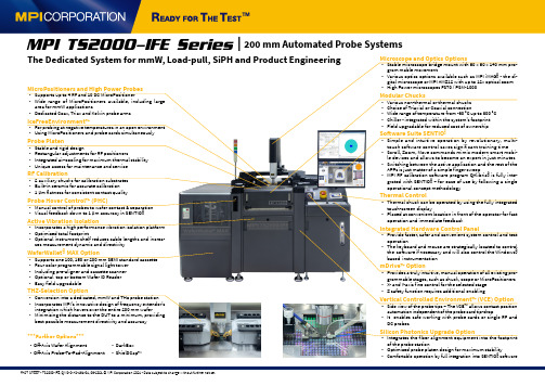
FACT SHEET - TS2000-IFE, QMS-C-AS-161-01, 06-2021 © MPI Corporation 2021 - Data subject to change without further notice.Microscope and Optics Options• Stable microscope bridge mount with 50 x 50 x 140 mm pro-gram mable movement• Various optics options available such as MPI iMAG® - the di-gital microscope or MPI AMZ12 with up to 12x optical zoom• High Power microscopes FS70 / PSM-1000Modular Chucks• Various non-thermal or thermal chucks• Choice of Triaxial or Coaxial connection• Wide range of temperature from -60 °C up to 300 °C• Chiller - integrated within the system’s footprint• Field upgradable for reduced cost of ownershipSoftware Suite SENTIO®• Simple and intuitive operation by revolutionary, multi-touch software control saves significant training time• Scroll, Zoom, Move commands mimic modern smart mobi-le devices and allows to become an expert in just minutes• Switching between the active application and the rest of theAPPs is just matter of a simple finger sweep• MPI RF calibration software program QAlibria® is fully inte-grated with SENTIO® – for ease of use by following a singleoperational concept methodologyThermal Control• Thermal chuck can be operated by using the fully integratedtouch-screen display• Placed at convenient location in front of the operator for fastoperation and immediate feedbackIntegrated Hardware Control Panel• Provide faster, safer and convenient system control and testoperation• The keyboard and mouse are strategically located to controlthe software if necessary and will also control the Windows®based instrumentationmDrive™ Option• Provides a truly intuitive, manual operation of all existing pro-grammable stages, such as chuck, scope or MicroPositioners• X- and Y-axis fine control for the selected stage• Z safety function requires additional enablingVertical Controlled Environment™ (VCE) Option• Side view of the probe tips – The VCE TM allows contact positionautomation independent of the probe card tip-drop• It enables safe working with probe cards or single RF andDC probesSilicon Photonics Upgrade Option• Integrates the fiber alignment equipment into the footprintof the probe station• Optimized probe platen design for maximum stability• Comfortable operation by full integration into SENTIO® software MicroPositioners and High Power Probes• Supports up to 4 RF and 10 DC MicroPositioner• Wide range of Mic roPositioners available, inc luding largearea for mmW applications• Dedicated Coax, Triax and Kelvin probe armsIceFreeEnvironment™• For probing at negative temperatures in an open environment• Using MicroPositioners and probe cards simultaneouslyProbe Platen• S table and rigid design• R ectangular adjustments for RF positioners• I ntegrated air-cooling for maximum thermal stability• U nique access for maintenance and serviceRF Calibration• 2 auxiliary chucks for calibration substrates• Built-in ceramic for accurate calibration• 1 µm flatness for consistent contact qualityProbe Hover Control™ (PHC)• M anual control of probes to wafer contact & separation• Visual feedback down to 1 µm accuracy in SENTIO®Active Vibration Isolation• Incorporates a high performance vibration isolation platform• Optimized total footprint• Optional instrument shelf reduces cable lengths and increa-ses measurement dynamic and directivityWaferWallet® MAX Option• S upports one 100, 150 or 200 mm SEMI standard cassette• Four color programmable signal light tower• Including pre-aligner and cassette scanner• Optional top or bottom Wafer ID Reader• Easy field upgradableTHZ-Selection Option• C onversion into a dedicated, mmW and THz probe station• Incorporates MPI’s innovative design of frequency extender’sintegration which hovers over the entire 200 mm wafer• Minimizing the distance to the DUT to a minimum, providingbest possible measurement directivity and accuracyMPI TS2000-IFE Series| 200 mm Automated Probe SystemsThe Dedicated System for mmW, Load-pull, SiPH and Product Engineering***Further Options***• Off-Axis Wafer Alignment• Off-Axis Probe-To-Pad-Alignment• DarkBox• ShielDCap TM。
一种聚合物锂离子二次电池及其制备方法[发明专利]
![一种聚合物锂离子二次电池及其制备方法[发明专利]](https://img.taocdn.com/s3/m/f3524e33b14e852459fb5762.png)
专利名称:一种聚合物锂离子二次电池及其制备方法专利类型:发明专利
发明人:唐定国,慈云祥,其鲁,刘建红,晨晖,安平
申请号:CN200510059301.2
申请日:20050325
公开号:CN1838468A
公开日:
20060927
专利内容由知识产权出版社提供
摘要:本发明公开了一种聚合物锂离子二次电池及其制备方法。
本发明的聚合物锂离子二次电池,包括正极极片、负极极片和电解质,其中,所述负极极片上还有聚合物一无机粒子混合物膜。
本发明的聚合物锂离子二次电池通过在负极极片上成膜的方式来替代锂离子电池专用隔膜的使用,降低了电池的生产成本;而且原料来源丰富,价格低廉,制作过程操作简单,易于工业化生产;电池性能优良,首次充放电容量可以达到142mAh/g(LiCoO为正极材料)和98mAh/g(LiMnO为负极材料),每次充放电循环的放电容量衰减率低,约为0.4‰左右,具有广阔的应用前景。
申请人:北京大学,北京中信国安盟固利新材料技术研究院有限公司
地址:100871 北京市海淀区颐和园路5号北京大学
国籍:CN
代理机构:北京纪凯知识产权代理有限公司
代理人:关畅
更多信息请下载全文后查看。
三维电极-电芬顿耦合法试验装置处理石油采出水电极材料选择的试验研究

三维电极-电芬顿耦合法试验装置处理石油采出水电极材料选
择的试验研究
刘济嘉
【期刊名称】《辽宁化工》
【年(卷),期】2024(53)1
【摘要】以铁棒、碳棒作为阳极材料进行对比研究,可知铁棒阳极可以补充反应器中芬顿反应消耗的Fe2+,处理效果好,且化学性质稳定,适合做阳极材料;以活性炭、泡沫镍、纳米铁粒子电极对比研究可知,3mm柱状的活性炭与纳米铁混合粒子电极对石油采出水处理效果最好,当混合比例为2∶1时,对COD的去除率最大为
80.37%,对油脂的去除率最大为86.29%。
【总页数】6页(P68-73)
【作者】刘济嘉
【作者单位】辽宁省市政工程设计研究院有限责任公司
【正文语种】中文
【中图分类】TE133.9
【相关文献】
1.复极性三维电极-电芬顿耦合法处理苯酚废水的实验研究
2.三维电极-电Fenton 处理硝基苯废水电极材料与影响因素研究
3.泡沫镍三维电极电芬顿法预处理焦化废水效能研究
4.碳纤维类材料用于电芬顿体系电极的研究现状
5.阴极电芬顿法电极材料的选择及处理印染废水的研究
因版权原因,仅展示原文概要,查看原文内容请购买。
- 1、下载文档前请自行甄别文档内容的完整性,平台不提供额外的编辑、内容补充、找答案等附加服务。
- 2、"仅部分预览"的文档,不可在线预览部分如存在完整性等问题,可反馈申请退款(可完整预览的文档不适用该条件!)。
- 3、如文档侵犯您的权益,请联系客服反馈,我们会尽快为您处理(人工客服工作时间:9:00-18:30)。
ECS-FT电芬顿
芬顿(Fenton)试剂法是氧化处理难降解有机污染物的有效方法,Fenton试剂(Fe2+/ H2O2)体系反应原理是H2O2在 Fe2 +的催化作用下生成具有极高氧化电位的羟基自由基(•OH),•OH氧化降解废水中的有机污染物。
电芬顿技术(电催化氧化)是利用电化学法产生Fe2+和H 2O2作为芬顿试剂的持续来源,两者产生后立即作用生成具有高度活性的羟基自由基,使有机物得到降解。
本电芬顿反应系统中的Fe2+由由铁素体阳极氧化产生,部分H2O2由催化阴极产生。
电解槽通电时,体系中除产生·OH外,还有强絮凝、络合、吸附作用的Fe(OH)2、Fe(OH)3产生,对有机物的去除效果好。
电解槽内的电极反应如下:
阳极 Fe-2e-=Fe2+
2H2O-4e-=O2+4H+
阴极 2H2O+2e-=H2+2OH-
2H2O+O2=2H2O2
溶液中的反应Fe2+ +H2O2=·OH+OH-+Fe3+
Fe3++3OH- = Fe(OH)3
设备优势
体系中通过电解可持续产生高活性Fe2+和H2O2,克服了传统芬顿法中有机物的降解速率不均衡,先快后慢的现象,保证反应均衡,持续高效;
反应体系中,除羟基自由基的氧化作用外,还有阳极氧化、阴极还原,电吸附、电气浮、电凝聚等多种作用,处理效率比传统芬顿法高;
与传统芬顿法相比,电芬顿(电催化氧化)不需要现场加入大量药剂(只需要适量加入H2O2),节省了药剂费用;
占地面积小,废水停留时间短,处理过程快,条件要求不苛刻;
设备相对简单,电解过程需控制的参数只有电流和电压,易于实现自动控制;
处理过程相对清洁,只产生少量的污泥,是传统芬顿法污泥量的1/5-1/10。
应用范围
适用于高难度难降解有机废水前处理,可直接降解COD和将高分子结构有机物降解为易生物降解的小分子有机物,提高B OD/COD比,易于和其它方法结合,实现废水的综合治理。
适用于高难度难降解有机废水生化后深度处理,可将不可生化的有机物直接氧化成二氧化碳和水,达到深度处理达标排放的目的。