4 Hybrid组建实践-WindVane项目简述
AADvance系统介绍

控制器底板
报警连接器
24VDC系统 冗余供电
(基本无用)
处理器A串行 冗余接口 处理器A以太网 冗余接口
安全加密狗 连接器
加密狗底板供电, 保证组态下载,在线 更改组态安全等 通讯口集成在处理 器底板上,不配独立 通讯卡
电源与过程 信号端口
9100
与DCS通讯
工程师站 操作员站 工程师站 操作员站
处理器
单一输出模块在正常失电应用中符合SIL2 要求,在正常得电应用中符合SIL3,冗余都 满足SIL3要求
I/O端子板
I/O模块
系统组成
单控制器可左右两侧各带8个I/O底 板,共48块模块,最大带点768 底板为模块供电,处理器和I/O数 据提供内部连接,连接后,背板组 成了一个单一的机械整体; 模块的插入和移除不会对现场设备的 电路连接产生影响; 可在同一或不同I/O底板上单重化、
产品定位
项目规模:以中、小型项目为主(500点以下),少量大型ESD项目 应用领域:99%以上是ESD,少量FGS 应用行业:
AADance主要应用于化工、石 化、煤化工、精细化工等行业; 少量应用于造纸、制药和环保等 行业
系统硬件设计
系统软件设计 优劣势分析
系统组成
处理器底板 单一处理器符合SIL2要求,冗余符合 SIL3要求 I/O底板 单一输入模块符合SIL3要求
I/O背板
AI模块 DI模块
9300
9431/9432 9401/9402 8通道/16通道 24VDC,8通道/16通道
DO模块
DI端子板 AI端子板 DO端子板
9451
9831/9832/9833 9801/9802/9803 9851/9852
风河新版Hypervisor拓展嵌入式虚拟化支持

运 营 商 :工 程 队 的 熔 接 机 已配
备 ,熔 接 管 价 格 便 宜 ,熔 接 一 的 成 本 低 ,十 对 现 场 连 接 器 柬 说 ,在 成 本 H 上 有 吸 引力 。 F TTH是 采 用 熔 接 还 足 冷 接 ? 这
ojI ∈ 5理器 可在Fe s a 5 O 内核或I e O上 re c l e O mc e n I 器上执行不经 t 处理
50 核,与Qol r Q 不会带来任何干扰 。其所 具备的富协作功能 则能够帮助用户通过 所具备的特 点和优势包括:可支持飞 思卡尔的e Omc
任 何设备共享及处理 文档 ,以全新的方式 实现移 动协作 .并进一
SP I的组件中提 oP l功能 ,还能够提供 实时用户联系信息 。显 示 Hy evs r p rio的硬 件支持 范 围。
在线情形 及状态 ,支持语音 、消息及电子邮件等多种沟通方式0 该版 本平 台所具 备的 富沟通能 力允许 发起 即时电话 会议 , 能够将桌面 电话无 缝切换 或转接至无线L N A 电话 或者移动设备 ,
v I i r y ev o I \ d R e H p rs r 包含 了针对 多核硬件需求而特 别优化 / n v i 1 2
的操作 系统 、工具套 件 以及具备极佳 可伸 缩性、全面适应单核和多 核处理器硬件架构的嵌入 式虚 拟化平 台。 nl i r y ev o . Wi v pr ̄ r 2 dR e H s 1
缩 后 同定 住 光 纤 上 , 达 到 保 护 光 缆 的
hybrid配置实验
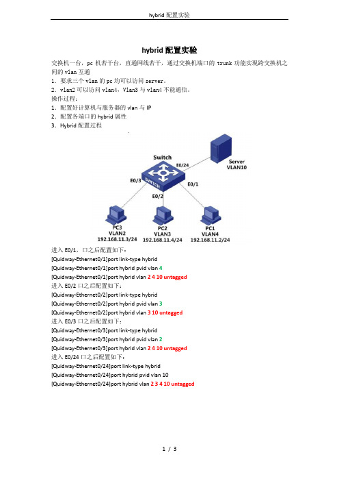
hybrid配置实验交换机一台,pc机若干台,直通网线若干,通过交换机端口的trunk功能实现跨交换机之间的vlan互通1.要求三个vlan的pc均可以访问server。
2.vlan2可以访问vlan4,Vlan3与vlan4不能通信。
操作过程:1.配置好计算机与服务器的vlan与IP2.配置各端口的hybrid属性3.Hybrid配置过程进入E0/1,口之后配置如下:[Quidway-Ethernet0/1]port link-type hybrid[Quidway-Ethernet0/1]port hybrid pvid vlan 4[Quidway-Ethernet0/1]port hybrid vlan 2 4 10 untagged进入E0/2口之后配置如下:[Quidway-Ethernet0/2]port link-type hybrid[Quidway-Ethernet0/2]port hybrid pvid vlan 3[Quidway-Ethernet0/2]port hybrid vlan 3 10 untagged进入E0/3口之后配置如下:[Quidway-Ethernet0/3]port link-type hybrid[Quidway-Ethernet0/3]port hybrid pvid vlan 2[Quidway-Ethernet0/3]port hybrid vlan 2 4 10 untagged进入E0/24口之后配置如下:[Quidway-Ethernet0/24]port link-type hybrid[Quidway-Ethernet0/24]port hybrid pvid vlan 10[Quidway-Ethernet0/24]port hybrid vlan 2 3 4 10 untagged以太网端口有三种链路类型:Access、Hybrid和Trunk。
hybrid 原理

hybrid 原理1. 什么是 hybrid 开发Hybrid 开发是一种结合了原生应用和 Web 技术的开发模式。
它允许开发者使用Web 技术(HTML、CSS、JavaScript)构建应用的用户界面,并使用原生技术(Android、iOS)访问设备的硬件和功能。
2. hybrid 原理概述Hybrid 应用的原理是通过 WebView 来加载本地的 Web 页面,并在页面中嵌入JavaScript Bridge,使 Web 页面能够与原生代码进行通信。
JavaScript Bridge 充当着连接两者的桥梁,它提供了一系列方法,使得 Web 页面可以调用原生接口,并获取原生资源。
具体来说,hybrid 开发主要有以下几个关键组成部分:2.1 WebViewWebView 充当了加载和渲染本地 Web 页面的角色。
WebView 可以视为一个顶层的容器,它可以将本地的 HTML、JavaScript 和 CSS 渲染成一个完整的页面。
2.2 JavaScript BridgeJavaScript Bridge 是一个连接原生代码和 Web 页面的桥梁。
它允许 Web 页面调用原生的接口和方法,以及获取设备的硬件和功能。
在原生代码中,我们需要实现一个 JavaScript Bridge,它会将 JavaScript 代码解析并执行,然后返回结果给JavaScript。
2.3 原生封装原生封装是指将常用的原生功能和接口封装成 JavaScript 接口,以方便 Web 页面调用。
比如,封装获取设备信息的接口、调用摄像头的接口等。
2.4 Web AppWeb App 是一个使用 HTML、CSS 和 JavaScript 编写的应用程序。
它被加载到WebView 中进行展示和执行。
Web App 可以通过 JavaScript Bridge 调用原生封装的接口,以实现访问设备功能和硬件的目的。
3. hybrid 开发流程下面是一般的 hybrid 开发流程:3.1 确定需求和功能在进行 hybrid 开发之前,我们需要明确应用的需求和功能,确定好要实现的功能和界面。
Vensys变桨系统简介

f. 温度传感器 (Pt 100)
这种温度传感器是利用导 体铂(pt)的电阻值随温 度的变化而变化的特性来 测量温度的。通常这样的 温度传感器可以测量负200 到正500摄氏度的范围,而 且在这个温度范围下,铂 的电阻值和温度具有良好 的线性关系。在Vensys变 桨系统中主要用于变桨电 机温度、柜体温度、NG5温 度、超级电容温度测量。
3.2变桨线路连接图
3.3变桨系统驱动原理
变桨控制柜通过安装在电机尾部的旋转编码器来检测叶片所在的角度。 分别安装在桨叶对应的87度、5度接近开关,提供了附加的位置检测功能。安装在桨叶对 应92度的限位开关提供了当位置检测失效的情况下的安全保护功能。 通过变桨逆变器AC2驱动变桨电机进行桨叶角度调整。 直流开关电源NG5将400VAC转换为60VDC,为超级电容充电同时为24VDC电源供电。 3.4变桨控制流程图 Vensys变桨系统动作方式分为:自动模式、手动模式、强制手动模式,现根据流程图对动 作模式进行说明。控制流程图如下:
四、主要元件实物认知及功能原理
4.1 变桨柜在轮毂中的安装
4.2 变桨柜内部布局
4.3 变桨柜主要元器件 控制柜内部电源及控制检测部分: a. 开关电源(NG5) b. 变桨变频器(AC2) c. 超级电容 d. A10自制模块 e. BC3150及beckoff模块 f. 温度检测(PT100) 控制柜外部驱动及检测部分: g. 变桨电机 h. 旋转编码器 i. 温度检测(PT100) j. 0°和87 °接近开关及90°限位开关 k. 滑环
KL4001 模拟量输出模块可输出 0 V 到 10 V 范围的信号。该模块可为处理层提供分辨 率为 12 位的电气隔离信号。总线端子的输出通道有一个公共接地电位端。KL4001是单通道 型,适用于带有接地电位的电气隔离信号。它通过运行 LED 显示端子与总线耦合器之间的数 据交换状态。
利用红帽Piranha方案实现WEB负载均衡-DR模式

Redhat 5.4 自带Piranha 搭建DR模式LVSAuthor:Michael (duhong24@)Version:1.1Update time:Sunday, December 04, 2011目录1.作者想说的 (3)2.环境介绍 (3)3.Piranha方案基本简绍 (4)2.1.Piranha方案优点: (4)2.2.配置简洁高效: (4)2.3.WEB配置界面. (4)2.4.完整的功能: (4)2.5.Piranha方案原理结构描述: (4)4.Piranha方案基本套件安装: (6)3.1.安装软件 (6)3.2.配置文件介绍 (6)3.3.Piranha配置 (6)3.4.防火墙配置 (9)3.5.测试 (10)5.LVS配置文件详解及相关安全技巧介绍 (10)4.1.lvs.conf 配置及详解 (10)4.2.修改Piranha登陆用户名及监听端口? (10)4.3.如果启动/etc/init.d/piranha-gui start报错 (11)1.我想说的根据本人阅读习惯,网上的文档几乎都是实验环境,草草实验了事,甚至更多是简单的COPY,典型的“拿来主义”,在实际环境中有很多问题,本文档在网上下载下来后,经过实际客户环境需求验证后,对文档做了一些补充和调整,从格式上规范了一下,请读者认真领会,有疑问和不足的地方可以邮件给我,一起交流经验心得。
切记勿将“拿来主义”应用到底,要不得!2.环境介绍实验平台: redhat Enterprise 5.4实验目标:本次按照客户需求实现后端两台服务器负载均衡,利用redhat自带的Piranha搭建DR模式LVS;快速撑握和理解Piranha方案,并利用15分钟构建WEB高可用负载均衡解决方案.结构:本次使用单机搭建LVS-ACTIVE:192.168.1.210LVS-BACKUP: 192.168.1.211(未使用)LVS-VIP: 192.168.1.212Realsever: 192.168.1.204, 192.168.1.205实际TOP如下:3.Piranha方案基本简绍2.1.Piranha方案优点2.2.配置简洁高效配置简便一个lvs.conf配置文件即可搞定(类keepalived方案.)2.3.WEB配置界面.WEB配置对于那些不懂LVS配置的人员来说非常吸引力,你几乎只要花15分钟就可以配置好一个完美的负载均衡及高可用性方案.2.4.完整的功能主备LVS (Load Balancer)的Heartbeat和HA (pulse,send_arp)LoadBalancer和Real Server间进程服务的Heartbeat (nanny)IPVS功能(lvsd)IPVS的管理(ipvsadm)2.5.Piranha方案原理结构描述:Piranha方案是基于LVS基础上设计的一套负载均衡高可用解决方案.LVS运行在一对有相似配置的计算机上:一个作为活动LVS Router(Active LVS Router),一个作为备份LVS Router(Backup LVS Router)。
hybrid模式工作原理

hybrid模式工作原理随着全球数字化的深入发展,越来越多的企业开始采用云技术,特别是在云端数据库存储方面。
随之而来的是更多的云服务商和软件供应商纷纷推出了他们的hybrid、多云和混合云解决方案,以帮助企业实现数据和应用程序的云中转移和迁移。
那么究竟hybrid模式是如何工作的?首先,hybrid模式是指企业同时使用两种或更多的云服务。
一种是公有云,即互联网上所有用户都可以访问的云服务,例如Amazon Web Services、Microsoft Azure、Google Cloud等;另一种是私有云,即数据和应用程序只能被内部人员访问的云服务。
hybrid模式与其他类型的云模式不同,因为它允许企业将应用程序和数据存储到公有云和私有云中。
其次,hybrid模式的工作原理是基于API的,即应用程序界面。
API是指应用程序向其他程序提供数据和功能的方式。
在hybrid模式中,API扮演了非常重要的角色,它允许作为提供方的公有云和作为使用方的私有云之间进行通信。
因此,在使用hybrid模式时,API必须能够正常工作。
接下来,hybrid模式通过云中转移数据和应用程序。
当企业需要将应用程序或数据从一个云到另一个云时,它们使用API将数据从一个云服务提供商传输到另一个云服务提供商。
通过转移工作,企业可以最大限度地降低云服务的成本,同时使用不同的私有和公有云服务,以最好地满足他们的需求。
最后,Hybrid模式也提供了更高的安全性。
在Hybrid模式中,企业可以在私有云环境中存储和处理敏感数据,这可以使他们更好地控制数据安全。
同时,在公有云中,他们可以存储和处理非敏感数据,进而降低了成本。
总之,hybrid模式的工作原理是在公有云和私有云之间使用API实现通信,通过云中转移数据和应用程序,实现对数据的最大限度的安全性。
正因如此,hybrid模式成为越来越多企业的选择。
WIZORD 4 安装手册说明书

GROUP OF COMPANIESINSTALLER MANUALELECTRIC FENCE ENERGISERINTRODUCTION (3)DISCLAIMER (3)MOUNTING / BATTERY REPLACEMENT PROCEDURES (4)CONNECTION TO THE FENCE (5)CONNECTION / CONFIGURATION DIAGRAM (6)PC BOARD REPLACEMENT PROCEDURES (7)SERVICE CONDITIONS (8)APPENDIX A…………………………………………………………………………………. 9-11I N T R O D U C T I O NThe WIZORD 4 is a battery (12V 7AH nominal) operated energizer suitable for connection to mains (230V 50Hz nominal).The batteries to be used are rechargeable lead-acid batteries. Non-rechargeable batteries must NOT be used. The lead-acid batteries require venting and it is imperative that the energizer be situated in a well-ventilated area.D I S C L A I ME RNEMTEK Holdings (Pty) Ltd or any of its subsidiary companies does not guarantee that the operation of the product will be uninterrupted or totally error free.Energizer specifications may be altered without prior notification.The installer is referred to the definitions and general requirements in Appendix A.The installer must take into consideration the applicable municipal laws concerning the installation of electric fences. General guidelines are available, or refer to the website: . International standards can be viewed at http://www.iec.ch and South African standards on http://www.sabs.co.za.*Energizer to be mounted vertically against a flat surface, in well ventilated area.OPTION 1: NO EARTH LOOP MONITORINGBridge the earth OUT to earth RETURN. The unit will now function as per theold version WIZORD.OPTION 2: EARTH LOOP MONITORING; GOOD SOIL EARTHINGOPTION 3: EARTH LOOP MONITORING; POOR SOIL EARTHING EARTHFEARTHFJUMPER OPERATION:Jumper Description: Inserted: Removed:JP1 Switch input enabled See next tableJP2 Switch input delay (4 minutes) Switch input instantaneous Jumper Description: Inserted: Removed:JP1 See previous table Remote on/off enabled JP2 Plastic tab switch enabled Plastic tab switch disabled * JP3 – Reserved for future use* JP4 – Bypass safety switch. Not to be installed during normal use.terminals if connected PC Board back) into place the PC Board into place.Also ensure that the opto-coupler PC Board REMOVAL: REPLACEMENT:S E R V I C E C O N D I T I O N SOn removing the energizer lid and disconnecting JP3, one or more of the following service conditions may be displayed (Lit LED):FUSE DESCRIPTION & FAULT SYMPTOMSHOW TO CHECK: (ALL FUSES ARE 2 AMPERE FAST BLOW)F1: Energizer does not operate when mains is switched offF2: Siren or strobe light does not operate (ensure that the unit wasswitched off with no fault conditions)F3:Power light is not lit, even when mains is presentGOODSystem TimeoutFence Interference Over-temperature Energizer Faulty or Tampered withBattery Flat SERVICEBASIC DEFINITIONS:Electric Fence: a barrier which includes one or more electric conductors, insulated from earth, to which electric pulses are applied by an energiserConnecting Lead: an electric conductor, used to connect the energiser to the electric fence or the earth electrodeElectric Security Fence: a fence used for security purposes which comprises an electric fence and a physical barrier electrically isolated from the electric fencePublic Access Area: any area where persons are protected from inadvertent contact with pulsed conductors by a physical barrier.Pulsed Conductors: conductors which are subjected to high voltage pulses by the energiser.Secure Area: an area where a person is not separated from pulse conductors below 1,5m by a physical barrier.GENERAL REQUIREMENTS FOR ELECTRIC SECURITY FENCES:Electric fences shall be installed and operated so that they cause no electrical hazard to persons, animals or their surroundings.Electric fence constructions which are likely to lead to the entanglement of animals or persons shall be avoided.An electric fence shall not be supplied from two different energizers or from independent fence circuits of the same energiser.For any two different electric fences, each supplied from a different energiser independently timed, the distance between the wires of the two electric fences shall be at least 2m. If this gap is to be closed, this shall be effected by means of electrically non-conductive material or an isolated metal barrier.Barbed wire or razor wire shall not be electrified by an energiser.Any part of an electric fence which is installed along a public road or pathway shall be identified at frequent intervals by prominently placed warning signs securely fastened to the fence posts or firmly clamped to the fence wires. The size of the warning signs shall be at least 100mm x 200mm. The background colour of both sides of the warning plate shall be yellow. The inscription on the plate shall be black . The warning sign shall typically appear as depicted in Figure x. The inscription shall be indelible, inscribed on both sides of the warning plate and have a height of at least 25 mm.Warning signs shall be placed at- each gate- each access point- intervals not exceeding 10m- adjacent to each sign relating to chemical hazards for the information of emergency services.Gates in electric security fences shall be capable of being opened without the person receiving an electric shock.The energiser earth electrode shall penetrate the ground to a depth of at least 1m. The distance between any electric security fence earth electrode and other earth systems shall not be less than 2m.Connecting leads that are run inside buildings shall be effectively insulated from the earthed structural parts of the building. This may be achieved by using insulated high voltage cable.Connecting leads that are run underground shall be run in a conduit of insulating material or else insulated high voltage cable shall be used. Care shall be taken to avoid damage to the connecting leads due to external factors.Connecting leads shall not be installed in the same conduit as the mains supply wiring, communication cables or data cables.Connecting leads and electric fence wires shall not cross above overhead power or communication lines.Mains supply wiring shall not be installed in the same conduit as signalling leads associated with the electric security fence installation.Crossings with overhead power lines shall be avoided wherever possible. If such a crossing cannot be avoided, it shall be made underneath the power line and as nearly as possible at right angles to it.If connecting leads and electric fence wires are installed near an overhead power line, the clearances shall not be less than those shown in Table 1. Power Line Voltage (V) Clearance(m)Equal or less than 1 000 3>1 000 and equal or less than 33 000 4>33 000 8Table 1If connecting leads and electric fence wires are installed near an overhead power line, their height above the ground shall not exceed 3m.11 Where an electric security fence passes below bare power line conductors, the highest metallic element shall be effectively earthed for a distance of not less than 5m on either side of the crossing point.This height applies either side of the orthogonal projection of the outermost conductors of the power line on the ground surface, for a distance of- 2m for power lines operating at a nominal voltage not exceeding 1 000 V- 15m for power lines operating at a nominal voltage exceeding 1 000V Electric security fences and their ancillary equipment shall be installed, operated and maintained in a manner that minimizes danger to persons, and reduces the risk of persons receiving an electric shock unless they attempt to penetrate the physical barrier, or are in a secure area without authority. Exposed conductive parts of the physical barrier shall be effectively earthed. A spacing of 2.5 m shall be maintained between uninsulated electric fence conductors or uninsulated connecting leads supplied from different energizers. This spacing may be less where conductors or connecting leads are covered by insulating sleeving, or consist of insulated cables, rated to at least 10kV.This requirement need not apply where the separately energized conductors are separated by a physical barrier, which does not have any openings greater than 50mm.A vertical separation of not less than 2m shall be maintained between pulsed conductors fed from different energizers.Ensure that all ancillary equipment connected to the electric security fence circuit provides a degree of isolation between the fence circuit and the supply mains equivalent to that provided by the energiser. Protection from the weather shall be provided from the ancillary equipment unless this equipment is certified by the manufacturer as being suitable for use outdoors, and is of a type with a minimum degree of protection IPX4.。
- 1、下载文档前请自行甄别文档内容的完整性,平台不提供额外的编辑、内容补充、找答案等附加服务。
- 2、"仅部分预览"的文档,不可在线预览部分如存在完整性等问题,可反馈申请退款(可完整预览的文档不适用该条件!)。
- 3、如文档侵犯您的权益,请联系客服反馈,我们会尽快为您处理(人工客服工作时间:9:00-18:30)。
其他的思路—支付宝实践
TO DO List:
1.首页H5化,经历了 pagekit这种native方案本 地渲染的规则后,使用H5 化是否能解决多平台运营 统一的问题,同时亦需要 关注性能。
4.Webview主动进行web 页面的js注入,保证外链 也可以享有windvane函数 的功能。
3.基于Hybrid的全面降级 方案。经历过双十一的冲 击,手机客户端在此类特 殊时期能否保证使用 hybrid的降级方案保证手 机端当天的可用性。
• 有整套解决方案
多平台统 一体验 (交互运 营) 降低开发 成本 (前 端)
动态部署 插件化 (客户端)
WindVane是什么?
WindVane 提供的现有功能
1)可定制化UI组件,包含了一个可以直接使用的UIViewController。 2)资源本地缓存,资源预置打包服务。 3)Wap与本地功能模块通信交互。
Hybrid组件实践— WindVane 项目简述
宗心/于佳 颜垣/曲子深
Web vs. Native
• Web • 交互体验灵活
– UI组件和布局
• Native • 用户体验高
– 性能 – 符合平台特性
• 易于理解和使用
– 通用的开发技术, 与平台无关 – 开发效率,资源
• 计算资源丰富
– GPS,Camera等硬件 特性 – 存储,网络
2.基于本地Html页面的 Hybrid插件化,类似支付 宝客户端的方案,插件化 的动态更新可用性等等, 亦需要保证用户体验
Other...
。
配合全局导航规则下的拦截规则
通过jsbridge针对native页面 或本地功能调用
除此之外: 1.使用了全局的cache策略,并支持预置打包的cache策略,以减 少页面的读取时间。 2.默认定制了加载控制,前进后退等导航功能,也可在此基础上 定制webview的UI 3.最新接入多个windvane.js的相关函数,用以调用本地native方 法,包含地理位置服务,摇一摇功能,跨域cookies等方案。 4. hybrid组件基于手机淘宝站点,将wap站点的业务模块进行包 装,形成Hybrid的协议化方式组件。通过协议化标准化的方式提 供给客户端使用。服务端的改动将不会导致客户端的不可用。 例如waplugin://shoppingcart
4)Wap调用本地功能的JSBridge通信服务。
5)>25 个基于wap淘宝站点的Hybrid组件。 6)可自选择SDK接入层次的API。
淘宝主客户端
天猫客户端
windvane 一淘客户端 聚划算客户端
主客户端已使用场景
还及有 有早爱 现期等 在版页 的面 微中的 淘的直 详直接 情充接 页模入 块, ,以