【1】EDC的M3资源介绍_讲稿
Bonitron M3526DC DC Motor Ramp Starter 产品说明书

Model M3526DCDC Motor Ramp StarterCustomer Reference ManualWeb: ●Tel: 615-244-2825 ●Email:*****************Bonitron, Inc.2Bonitron, Inc.Nashville, TNAn industry leader in providing solutions for AC drives.A BOUTB ONITRONBonitron designs and manufactures quality industrial electronics that improve the reliability of processes and variable frequency drives worldwide. With products in numerous industries, and an educated and experienced team of engineers, Bonitron has seen thousands of products engineered since 1962 and welcomes custom applications.With engineering, production, and testing all in the same facility, Bonitron is able to ensure its products are of the utmost quality and ready to be applied to your application.The Bonitron engineering team has the background and expertise necessary to design, develop, and manufacture the quality industrial electronic systems d emanded in today’s market. A strong academic background supported by continuing education is complemented by many years of hands-on field experience. A clear advantage Bonitron has over many competitors is combined on-site engineering labs and manufacturing facilities, which allows the engineering team to have immediate access to testing and manufacturing. This not only saves time during prototype development, but also is essential to providing only the highest quality products.The sales and marketing teams work closely with engineering to provide up-to-date information and provide remarkable customer support to make sure you receive the best solution for your application. Thanks to this combination of quality products and superior customer support, Bonitron has products installed in critical applications worldwide.Bonitron, Inc.3AC D RIVE O PTIONSIn 1975, Bonitron began working with AC inverter drive specialists at synthetic fiber plants to develop speed control systems that could be interfaced with their plant process computers. Ever since, Bonitron has developed AC drive options that solve application issues associated with modern AC variable frequency drives and aid in reducing drive faults. Below is a sampling of Bonitron’s current product offering.W ORLD C LASS P RODUCTSUndervoltage SolutionsOvervoltage SolutionsUninterruptible Power for Drives(DC Bus Ride-Thru) Voltage Regulators Chargers and DischargersEnergy StorageBraking Transistors Braking Resistors Transistor/Resistor ComboLine RegenerationDynamic Braking for Servo DrivesCommon Bus SolutionsPortable Maintenance SolutionsSingle Phase Power Supplies 3-Phase Power Supplies Common Bus DiodesCapacitor Formers Capacitor TestersPower Quality SolutionsGreen Solutions12 and 18 Pulse KitsLine RegenerationM3526DC1.I NTRODUCTION (5)1.1.Who should use (5)1.2.Purpose and Scope (5)1.3.Manual version and change record (5)Figure 1-1: Model M3526DC-U050 DC Motor Ramp Starter (5)1.4.Symbol Conventions Used in this Manual and on Equipment (6)2.P RODUCT D ESCRIPTION (7)2.1.Part Number Breakdown (7)Figure 2-1: Example of M3526DC Part Number Breakdown (7)Table 2-1: Voltage Ratings (7)Table 2-2: Option Codes (7)2.2.General Specifications Chart (8)Table 2-3: General Specifications (8)2.3.General Precautions and Safety Warnings (9)3.I NSTALLATION I NSTRUCTIONS (11)3.1.Environment (11)3.2.Unpacking (11)3.3.Mounting (11)3.3.1.M3526DC Motor Ramp Starter Mounting (11)3.4.Wiring and Customer Connections (11)3.4.1.Power Wiring (11)Figure 3-1: M3526DC Power Connections (14)Figure 3-2: M3526DC User I/O Diagram (15)4.O PERATION (17)4.1.Functional Description (17)4.2.Features (17)4.2.1.LEDs (17)4.3.Ramp – UP Process (17)5.E NGINEERING D ATA (19)5.1.Fuse Selection (19)Table 5-1: Fuse Current Rating Requirements (19)5.2.Dimensions and Mechanical Drawings (20)Figure 5-1: M3526DC Enclosure Dimensional Outline (20)4User’s Manual1. I NTRODUCTION1.1. W HO SHOULD USEThis manual is intended for use by anyone who is responsible for integrating, installing,maintaining, troubleshooting, or using this equipment with any DC motor.Please keep this manual for future reference.1.2. P URPOSE AND S COPEThis manual is a user’s guide for the model M3526DC-U050 DC motor ramp startersystem. It provides you with the necessary information to successfully install and usethe M3645 modules in your application.In the event of any conflict between this document and any publication and/ordocumentation related to the application, the latter shall have precedence.1.3. M ANUAL VERSION AND CHANGE RECORDInitial release of the manual was revision 00.Updated manual release was revision 01a.Figure 1-1: Model M3526DC-U050 DC Motor Ramp Starter5M3526DC6 1.4. S YMBOL C ONVENTIONS U SED IN THIS M ANUAL AND ONE QUIPMENTDANGER!DANGER!CAUTION!CAUTION!User’s Manual72. P RODUCT D ESCRIPTIONThe function of the model M3526DC DC motor ramp starter is to accelerate the motor smoothly, on command, from stall to full voltage and hold it at full voltage with a bypass contactor until the run command is removed.2.1. P ART N UMBER B REAKDOWNFigure 2-1: Example of M3526DC Part Number BreakdownB ASE M ODEL N UMBERThe base model number for all motor ramp starter units is M3526DC .I NPUT V OLTAGE R ATINGA code letter represents the DC input voltage to the M3526DC. The DC motor ramp starter module will draw power from the DC bus. The See Table 2-1 for available voltage ratings.Table 2-1: Voltage Ratings R ATING C ODEN OMINAL V OLTAGEU120 VDCO UTPUT C URRENT R ATINGA 3-digit number represents the maximum continuous DC current (Amps) the module can sustain.O PTIONSTwo added options are available.Table 2-2: Option CodesO PTION C ODED ESCRIPTIONC RUN command contact input, Motor Over Temperature contact input MDoor mounted Motor Control AmmeterB ASE M ODEL N UMBER I NPUT V OLT AGE O UTPUTC URRENT O PTIONSM3526DCU 050 MM3526DC8 2.2. G ENERAL S PECIFICATIONS C HARTTable 2-3: General SpecificationsUser’s Manual92.3. G ENERAL P RECAUTIONS AND S AFETY W ARNINGSDANGER!CAUTION!ANY QUESTIONS AS TO APPLICATION, INSTALLATION OR SERVICE SAFETY SHOULD BE DIRECTED TO THE EQUIPMENT SUPPLIER.M3526DCThis page intentionally left blank 10User’s Manual 3. I NSTALLATION I NSTRUCTIONSCAUTION!Proper installation of the model M3526DC DC motor ramp starter should be accomplished following the steps outlined below. Be sure to refer to the DC motor instruction manual as these steps are performed. Please direct all installation inquiries that may arise during the installation and start-up of this product to the equipment supplier or system integrator.3.1. E NVIRONMENTThe module should be installed in an area protected from moisture and falling debris.Buildup of dust or debris may cause poor performance and possibly a failure.Operating in a wet environment can pose a shock hazard. The recommendedtemperature range for operating this module is 0 to +50︒C.Device shall be installed in a Pollution Degree 2 environment.3.2. U NPACKINGUpon receipt of this product, please verify that the product received matches theproduct that was ordered and that there is no obvious physical damage to the unit. Ifthe wrong product was received or the product is damaged in any way, please contactthe supplier from which the product was purchased.3.3. M OUNTING3.3.1. M3526DC M OTOR R AMP S TARTER M OUNTINGThe installation site for the M3526DC should be chosen with several considerations inmind:•When mounting the units the conduit access for field wiring is provided on the top of the enclosure.•The unit requires a minimum clearance of two (2) inches in all directions around it when not mounted near a heat source. Heat sources may increase necessaryclearances.•Unit should not be exposed to falling debris or condensation.Once the installation site has been selected as outlined above, the unit should bemounted in place.3.4. W IRING AND C USTOMER C ONNECTIONSBe sure to review all pertinent motor system documentation as well as the informationlisted below before proceeding.3.4.1. P OWER W IRINGCAUTION!Only qualified electricians should perform and maintain the interconnection wiring of this product. All wiring should be in accordance with local codes. The Model M3534DC-U050 "DC Motor Ramp Starter" system is powered from an external 120VDC input feed connected at the unit’s input power disconnect switch. This disconnect switch, which has an instantaneousM3526DCover current trip rating of 2400 amps, is followed by two FWX-100 100Asemiconductor fuses located, one per leg, in both the positive andnegative legs of the power feed. Once fused, main power is routed to theprecharge and IGBT switching circuitry as well as the bypass contactor,and also provides the source for control power within the system.3.4.1.1. C ONTROL P OWER,120VDC I NPUT V OLTAGE (D ISCONNECTSWT)Make the 120VDC input voltage connections at main disconnect switchterminals TS1-1 (Pos.) and TS1-2 (Neg.). Terminals accept 4AWG to4/0AWG wire. Tighten terminal screws securely.Control power for the DC Motor Ramp Starter is derived from the fused120VDC main power input previously described. Both the positive andnegative legs of this input are fused using ATM-10 10A fuses. Oncefused, the 120VDC control source is routed to the input of the 24VDCcontrol power supply as well as to the 3526C2 Control board. TheControl board then handles applying the 120VDC control source to themotor field winding and the bypass contactor coil at appropriate times asdictated by system conditions.The 24VDC control power supply provides power for four aspects of theDC Motor Ramp Starter system. First, the supply provides 24VDCdirectly to the 3526C2 Control board to power all on-board logic relaysas well as the precharge relay. Second, the supply provides a sourcefor the 3527S1 DC/DC Converter board which provides ±15VDC to the3526C2 Control board to power all control circuitry. Third, the supplypowers the "POWER" and "MOTOR RUNNING" LEDs on the door ofthe enclosure. Fourth, the supply provides power for the internal coolingfan via a K2 "RUN" relay contact.With 24VDC present and no IGBT driver fault indicated, the DC MotorRamp Starter system should be ready to run as indicated by the closureof the dry contact of the K4 "READY" relay.DC B US I NPUTThe DC bus input may be connected to the DC bus of an AC drive, theDC output of a diode sharing unit, or to a common DC bus. If a reactoror choke are being used in the bus, make sure the actual connection is inparallel with filter capacitors of the drive/inverter.Using the ground stud provided, ground the chassis in accordance withlocal codes. Typically, the wire gauge will be the same as is used toground the attached drive.3.4.1.2. A RMATURE O UTPUT V OLTAGE (TS2-1,2)Make the armature output connections at terminals TS2-1 (Pos.) andTS2-2 (Ne g.). Terminals accept 3/8” ring lugs. Torque to 192 lb-in.maximum.3.4.1.3. 24V R UN C OMMAND (TS1-1,2)Make the 24V Run Command input connections at terminals TS1-1 (24VPos.) and TS1-2 (24V Neg.). Terminals accept 22AWG to 12AWG wire.Torque all terminal screws to 3.5 - 5.3 lb.-in.3.4.1.4. M OTOR R UNNING O UTPUT (TS1-3,4)User’s Manual The normally-open “Motor Running” status output contact closes whenmonitored motor current reaches approximately 10 amps.Interconnections for the “Motor Running” output signal are available atterminals TS1-3 (COM) and TS1-4 (N.O.) on field connection terminalstrip TS1. Terminals accept 22AWG to 12AWG wire. Torque terminalscrews to 3.5 - 5.3 lb.-in.3.4.1.5. R EADY O UTPUT (TS1-5,6)The normally-open “Ready” status output contact closes when 24VDCcontrol power is present on the control board and there are no IGBTdriver faults present. Interconnections for the “Ready” output signal areavailable at terminals TS1-5 (COM) and TS1-6 (N.O.) on field connectionterminal strip TS1. Terminals accept 22AWG to 12AWG wire. Torqueterminal screws to 3.5 - 5.3 lb.-in.3.4.1.6. F IELD ON O UTPUT (TS1-7,8)The normally-open “Field ON” status output contact closes when fieldcurrent is detected during the ramp-up process. Interconnections for the“Field ON” output signal are avail able at terminals TS1-7 (COM) and TS1-8 (N.O.) on field connection terminal strip TS1. Terminals accept 22AWGto 12AWG wire. Torque terminal screws to 3.5 - 5.3 lb.-in.3.4.1.7. O VERTEMP O UTPUT (TS1-9,10)The normally closed “Over-Temp” status output thermal switc h opens ifthe IGBT heatsink temperature reaches 160°F. The switch will closeagain when the heatsink temperature drops to approximately 130°F. Thethermal switch contact is rated for 1A at 30VDC or 0.5A at 125VAC.Interconnections for the “Field ON” ou tput signal are available at terminalsTS1-9,10 on field connection terminal strip TS1. Terminals accept22AWG to 12AWG wire. Torque terminal screws to 3.5 - 5.3 lb.-in.3.4.1.8. S WITCHED F IELD V OLTAGE O UTPUT (TS1-11,12)The “Switched Field Voltage” output is tur ned on when the ramp-upprocess begins. Make the “Switched Field Voltage” connections atterminals TS1-11(Pos.) and TS1-12(Neg.). Refer to motor data forcorresponding terminations. Terminals accept 22AWG to 12AWG wire.Torque terminal screws to 3.5-5.3 lb.-in.3.4.1.9. G ROUNDMake the Ground connection to terminal TS1-13. Terminal accepts22AWG to 12AWG wire. Torque terminal screw to 3.5-5.3 lb.-in.3.4.1.10. O PTION “C”:R UN C OMMAND C ONTACT I NPUT /M OTOR OTC ONTACT I NPUT (TS1-1,14-16)The RUN Command contact (N.O.) is connected between terminals TS1-1, TS1-16. The MOTOR O.T. contact (N.C.) is connected betweenterminals TS1-14 and TS1-15. Terminals accept 22AWG to 12AWG wire.Torque terminal screw to 3.5 - 5.3 lb.-in.M3526DCUser’s ManualM3526DCUser’s Manual 4. O PERATION4.1. F UNCTIONAL D ESCRIPTIONThe model M3526DC Motor Ramp Starter is to accelerate the motor smoothly whencommanded from stall to full voltage. Once at full voltage the DC Motor Ramp starterwill hold it a full voltage with a bypass contactor until the run command is removed.4.2. F EATURES4.2.1. LED SRed, yellow, and green LEDs indicate the status of the regen.4.2.1.1. P OWER (G REEN)I NDICATORThe green LED indicates that the unit is powered on.4.2.1.2. RUN C OMMAND (R ED)I NDICATORThe red LED indicates that the unit is has been commanded to run froman external 24VDC and the motor is beginning to ramp up.4.2.1.3. M OTOR R UNNING (Y ELLOW)I NDICATORThe yellow LED indicates that at least 10A of motor current have beenmeasured.4.2.1.4. B YPASS ON(Y ELLOW)I NDICATORThe yellow LED indicates that the Bypass indicator has turned On andthe Motor Ramp Starter has reached the steady state condition.4.3. R AMP –UP P ROCESSWhen the ramp-up process begins, the output of op-amp U3-A, (pins 1, 2, and 3 ofU3), will begin to ramp up from –15VDC to +15VDC. The "RAMP RATE" of the DCMotor Ramp Starter is normally factory set at approximately 10 seconds but can befield adjusted within a range of approximately 8–12 seconds using on-boardadjustment pot R18.During the first 1.5 volts of the ramp, Q1 will be turned ON which allows 2 things tohappen. First, the fused 120VDC control source is applied to the motor FIELDwinding. Second, the 24VDC control power is applied to the coil of the"PRECHARGE" relay. As motor field current is detected, the K5 "FIELD CURRENT"relay will be energized providing a dry contact closure suitable for monitoringpurposes. This contact is available at terminals 7 and 8 of the system ControlTerminal strip. When the "PRECHARGE" relay is energized, a short is made acrossthe precharge resistor thus connecting the 900μf, 400VDC filter capacitor to the inputpower bus.When the ramp voltage reaches 3 volts above it's starting voltage, the Pulse WidthModulator comparator U2-B, (pins 5, 6, and 7 of U2), becomes active. U2-Bcompares the slowly ramping voltage to a 2kHz triangular wave which is generatedby U1. This comparison results in the application of a rectangular wave of increasingduty cycle to IGBT gate driver module U4 (SKHI22A) which in turn drives the gate ofthe chopper IGBT (BSM200GAL120DLC) module. The IGBT chops the fixed120VDC input into a variable duty cycle 120V, 2kHz rectangular waveform which isapplied to an output filter composed of a fast diode, choke, and capacitor. Theoutput filter converts the rectangular voltage waveform back to the smooth DCvoltage which is applied to the motor.M3526DCAs the ramp voltage approaches +12VDC, the output of comparator U2-B becomesfully ON. When the ramp voltage reaches approximately +13.5VDC, the motorreaches full voltage and the bypass contactor turns ON. At this point, the motorcurrent bypasses the power chopper circuitry to flow through the contactor. The gatedriver to the IGBT remains ON but little or no current passes through the IGBT, thusreducing its losses to near zero while in this steady state condition.A Hall Effect current sensor in the DC output circuit is used to measure the motorcurrent output. The current sensor provides a motor current feedback signal of –4VDC per 50ADC of output current. This signal is monitored by op-amp U3-B, (pins5, 6, and 7 of U3). If, during the ramp-up process, the motor current signal indicatesthat the output current has exceeded a preset "CURRENT LIMIT" reference value, acorrective signal is injected into op-amp U3-A to reduce the ramp rate. If thiscondition occurs, the LD3 "I-LIM" LED on the control board will turn ON.The "CURRENT LIMIT" reference is factory preset to 100ADC and should not betampered with unless first consulting the engineering staff at Bonitron, Inc. However,if an adjustment is determined to be necessary, it can be accomplished via on-boardadjustment pot R40. A clockwise adjustment of this pot will produce an increase inthe "CURRENT LIMIT" reference setpoint.The motor current feedback signal is supplied to several additional functions of the3526C2 Control board. It is used to drive the 0–100 amp "MOTOR CURRENT"ammeter which is located on the door of the enclosure. The signal is also fed to theinput of comparator U2-A, (pins 1, 2, and 3 of U2), which controls the K3 "MOTORRUNNING" relay. When the motor current output rises above approximately 10ADC,the K3 relay is energized providing a dry contact closure suitable for monitoringpurposes. This contact is available at terminals 3 and 4 of the system Controlterminal strip.Dropping the "RUN" command will reverse this process by first opening the bypasscontactor thus diverting the motor current back through a full ON IGBT which thenramps to zero in 1–2 seconds, turning OFF the motor field current and Prechargecontactor at the end of the ramp down. The input filter cap remains across the inputbus with a resistor in series with it during its waiting period.User’s Manual 5. E NGINEERING D ATA5.1. F USE S ELECTIONBlown fuses typically indicate a semiconductor device failure or a severe transient. Inany case, blown fuses should not be replaced without first consulting Bonitron ascatastrophic damage can occur. Use Tables 6-6 and 6-7 when initially constructingthe system.Note: AC fuses must be J-type or equivalent.User’s Manual NOTES21M3526DC 22D_M3526_CMAN_vU050_01a 07/18/2017 521 Fairground Court ● Nashville, TN 37211 ● USATel: (615) 244-2825 ● Fax: (615) 244-2833 ● Web: ● Email:*****************。
EPIC3中文说明书综述

第一章简介1.1. EPIC-Ⅲ系统EPIC-Ⅲ(静电除尘器集成控制器)系统是ALSTOM电力公司第三代以微处理器为基础的电除尘器控制系统,其以太网版本包含了一个以太网连接,同时还包含一个带Web浏览器的Web服务器,你可以随意选取一台PC机作为Web服务器。
新型的EPIC-Ⅲ控制器可以作为一个独立单元进行操作,一个EPIC-Ⅲ控制器可以控制一台电除尘器的一个供电分区,因此通过以太网交换机连接在一起的多个EPIC-Ⅲ控制器则可以控制多个电除尘供电分区。
每个EPIC-Ⅲ内部的主控功能可以简化系统操作,另外还可在PC机上安装一个PC-MTU软件,用来监控整套设备(MTU=终端监控单元)。
图1 EPIC-Ⅲ系统以太网结构图FD_Ctrl彩色图形软件包,带有软件通信协议的主机网关可作为一个可选组件使用,见图2。
图2 装有可选FD_Ctrl软件的EPIC-Ⅲ系统1.2. EPIC-Ⅲ控制器EPIC-Ⅲ是一个以微处理器为基础的控制单元,它可以调节和控制电除尘器的输入电源,当气体温度、粉尘成分、气体流向等发生较大变动时,它可以使火花率维持在一个合适的值,它还可以调节整流器,当火花改变时调整输入电除尘的电流。
整个操作过程可以由Web浏览器、PC-MTU、FD_Ctrl或主机监控。
报警――当运行的工况超出了设定范围,EPIC-Ⅲ会产生警告报警或跳闸报警,报警信息会显示在Web服务器上,并由Web浏览器监控和复位。
如果使用PC-MTU软件,报警状态也会在其上显示,另外FD_Ctrl也可以显示报警信息。
模式――可以预设六种运行模式,每个EPIC-Ⅲ的运行模式可以从中选定。
ESP主控功能――EPIC-Ⅲ含有一个ESP主控功能,也就是说一个被设定为ESP主控单元的EPIC-Ⅲ可以控制以太网系统中所有的EPIC-Ⅲ(可设定范围),从而使ESP的总体性能更佳。
EPOQ ――带EPOQ算法运行时,可对电除尘器加以优化,使其在不同的负荷条件下达到最佳的收尘效率。
纵维立方m3 参数

纵维立方m3 参数一、概述纵维立方m3纵维立方m3是一款备受关注的电子产品,它以出色的性能和实用的功能赢得了大量用户的喜爱。
本文将详细介绍纵维立方m3的主要参数,分析其优缺点,并为大家提供购买建议。
二、纵维立方m3的主要参数1.尺寸和重量纵维立方m3的尺寸和重量适中,便于携带和存放。
其紧凑的设计让它在办公和家庭环境中都能占据最小的空间。
2.材质和颜色纵维立方m3采用高品质材质制成,具有良好的耐磨性和抗压性。
颜色方面,纵维立方m3提供了多种选择,以满足不同用户的审美需求。
3.容量和续航纵维立方m3具备大容量存储空间,可满足用户长时间使用的需求。
在正常使用情况下,其续航表现优秀,无需频繁充电。
4.性能和速度纵维立方m3搭载了高性能处理器,运行速度快,能迅速响应用户操作。
在处理多任务和大型应用时,表现稳定。
5.接口和扩展性纵维立方m3配备了丰富的接口,方便用户连接各种设备。
此外,它还具备良好的扩展性,便于用户在未来添加更多功能。
6.操作便捷性纵维立方m3的操作界面简洁直观,用户可以轻松上手。
无论是新手还是资深用户,都能快速掌握其操作方法。
三、纵维立方m3的优缺点分析1.优点(1)性能出色,运行速度快;(2)续航表现良好,减少充电次数;(3)操作便捷,易于上手;(4)接口丰富,扩展性强。
2.缺点(1)价格相对较高;(2)部分用户可能会觉得重量稍重。
四、购买建议和适用人群纵维立方m3是一款具备高性能、长续航和便捷操作的电子产品,适合对性能有较高要求、经常外出办公和追求操作便捷性的用户。
公安消防部队3G卫星车终端培训手册

28
© 华平信息技术股份有限公司
拨号设置-VPDN
为了保护公安消防图像数据传输通道安全性,终端3G拨号采用的是电信VPDN技术。 需要在3G拨号中填写电信分配的VPDN帐号密码,并购选“使用VPDN”选项。
29
© 华平信息技术股份有限公司
以太网设置
在使用中,如果遇到3G网络信号差的情况,可以与车载有线网络进行数据通信。打 开终端界面上的“系统”,点击“以太网”进行设置。
视频输入连接
2、连接USB摄像头 连接USB摄像头与HDS100的USB1接口。
USB摄像头 15
© 华平信息技术股份有限公司
3G网络连接
在3G的天线接口处连接上天线,标准便携箱中配有胶杆天线,背负时可直接使用。 如车载使用,建议换成3G车载吸盘天线,以便更好的接收与发射信号。
16
© 华平信息技术股份有限公司
40
© 华平信息技术股份有限公司
重启或关闭终端
需要关闭或重启终端,可以点击终端界面上的“退出”按钮,弹出关机对话框,选择 需要的操作即可。
41
© 华平信息技术股份有限公司
42
© 华平信息技术股份有限公司
25
© 华平信息技术股份有限公司
系统登录设置
在设置对话框中选择“帐号”选项卡,填写服务器地址、用户设备账号及密码。
地址:填写各总队创世平台服务器地址 比如:10.172.148.56 端口:默认4222,不可更改 用户账号:sxzd3g (陕西sn山西sx) 用户密码:123 设备账号:sxzd3g 设备密码:123 设备名称:**总队**支队3G终端 如陕西总队为:陕西总队3G终端,西安 支队为:陕西西安支队3G终端 按照命名规则统一在总队或部局图 像综合平台建好帐号,再把相关帐号信 息抄送给各总队进行备案。
CCOM公安3G视频图传
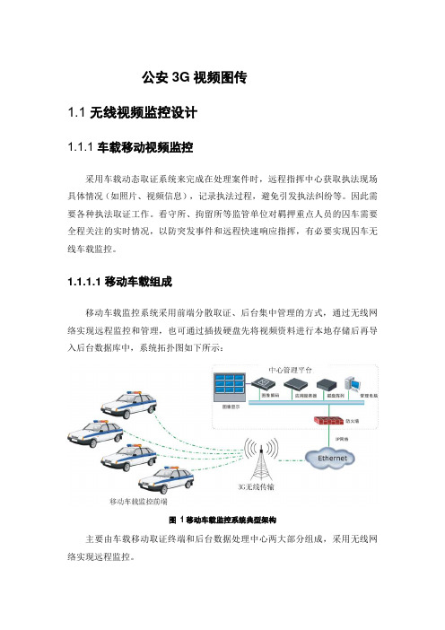
公安3G视频图传1.1 无线视频监控设计1.1.1 车载移动视频监控采用车载动态取证系统来完成在处理案件时,远程指挥中心获取执法现场具体情况(如照片、视频信息),记录执法过程,避免引发执法纠纷等。
因此需要各种执法取证工作。
看守所、拘留所等监管单位对羁押重点人员的囚车需要全程关注的实时情况,以防突发事件和远程快速响应指挥,有必要实现囚车无线车载监控。
1.1.1.1 移动车载组成移动车载监控系统采用前端分散取证、后台集中管理的方式,通过无线网络实现远程监控和管理,也可通过插拔硬盘先将视频资料进行本地存储后再导入后台数据库中,系统拓扑图如下所示:图1移动车载监控系统典型架构主要由车载移动取证终端和后台数据处理中心两大部分组成,采用无线网络实现远程监控。
系统获取的信息:执法车辆所在地位置信息(GPS定位信息)、事件整体行为视频(全景摄像机)、事件关键点信息(目标摄像机)、目标摄像机抓图、本车车速、目标车速、执法事件发生的时间等信息。
可以为执法部门的处罚工作提供强有力的证据,做到执法的公正、透明和可信。
1.1.1.2 移动车载功能1、视音频数据编解码采用H.264视音频编解码技术,将采集到的模拟视音频数据进行高效率数字编码。
2、录像存储取证主机对采集的视音频信号实时硬件同步压缩后进行本地存储,可供事件回放、数据备份、数据上传等需求。
存储介质可以是SD卡或2.5寸SATA硬盘。
3、GPS定位系统配备GPS定位模块。
当接收到卫星信号时,可实时在本地预览画面上显示本车车辆的地理信息和行驶速度,相关数据同样可以存储在录像资料中。
同时具备支持全球24个时区的GPS卫星校时功能,可每5分钟自动进行一次卫星校时,保证取证时间的精确。
4、延时关机在车辆引擎关闭后,设备将根据设置参数,再工作一段时间后才关机。
延时时长可设置。
5、夜间补光系统采用红外或白光补光技术,能适应不同车牌反光涂层,实现在夜间或光线环境不佳情况下的取证拍摄,满足全天候无线车载监控工作需求。
m3高速钢成分

m3高速钢成分
M3高速钢是一种常用的工具钢,其成分主要包括碳、硅、锰、铬、钨、钼和钒等元素。
碳是M3高速钢中最主要的元素之一,含量通常在1.0%~1.5%之间。
它能够提高钢的硬度和耐磨性,但过高的碳含量会导致钢的韧性降低。
硅和锰是M3高速钢中的重要合金元素,它们的含量分别为0.4%~0.8%和0.4%~1.0%。
硅能够提高钢的硬度和耐磨性,同时具有脱氧作用,防止钢的氧化。
锰能够提高钢的强度和韧性,并具有脱硫作用,减少钢中的硫含量。
铬是M3高速钢中的重要合金元素之一,含量通常在3.0%~5.0%之间。
它能够提高钢的硬度和耐磨性,同时具有抗腐蚀和抗氧化作用。
钨和钼也是M3高速钢中的重要合金元素,它们的含量分别为1.5%~2.5%和0.5%~1.5%。
钨能够提高钢的硬度和耐磨性,同时具有抗腐蚀和抗氧化作用。
钼能够提高钢的强度和韧性,并具有细化钢的组织结构的作用。
钒是M3高速钢中的另一种重要合金元素,含量通常在1.0%~2.0%之间。
它能够细化钢的组织结构,提高钢的硬度和耐磨性。
同时,钒还可以改善钢的切削加工性能。
此外,M3高速钢中还可能含有少量的钴、铝等元素,这些元素也可以进一步提高钢的硬度和耐磨性。
tribonm3简介和船制造建模过程
TRIBON船体生产设计应用Tribon系统是一套计算机辅助设计、生产及信自、集成软件系统,可用多种方法建立三维船舶数字模型。
应用统一的船舶数字模型,在船舶设计的各个阶段能够实现各专业之间的信息共享,从而可以通过网络实现并行设计,降低专业间的协调成本,减少设计和制造中的修改工作量,提高设计质量,缩短设计周期。
Tribon系统建模船体建模的目的是建立船体的信息模型,应用Tribon系统的以下模块进行船体生产设计:船体标准初始化模块(Initiate Hull Standards);平面建模模块(Planar Hull Modeling);曲面建模模块(Curved Hull Modeling);装配计划模块(Assembly Planning);焊接计划模块(Weld Planning);生产信息界面(Hull Production Interface);套料模块(Plate Nesting).各模块功能如下:船体标准初始化模块通过该模块对其它船体模块正常运行所需参数及文件进行配置,建立起船体生产设计所需的Tribon系统船体标准。
系统初始化工作是Tribon船体系统应用中很重要的一个环节,主要包括以下内容: 船型参数设置。
输人船型参照、结构参照、分段名、分段划分、定义肋位号和纵骨等信息;型材规格、端切形式和连接形式以及面板参数设置;贯穿孔和补板参数设置;坡口形式参数设置;肘板类型规格参数设置;材质参数设备;零件编码参数设置;套料参数设置。
平面建模模块利用该模块输人结构数据,进行船体内部平面板架结构的建模工作,除定义结构信息,还可加放相应的工艺信息,白动进行零件编号等,建模完成后出分段结构图。
平面建模与曲面建模是同时进行、交叉作业的,平面建模的比重较大。
因为平面建模要参照曲面建模的结果,通常曲面建模要先于平面建模。
曲面建模模块利用该模块进行曲面构件的结构建模工作,主要是外板板缝线生成,外板型材生成和曲面(通常指外板)板架的生成。
tribonm3培训演示文稿

Gu liqin Technical Consultant
第一章 简介
1 简介
本课程是为系统管理员设计的,如系统安装,License 管理,项目设置等。对应于各设计专业的特别设置,将在另 外的课程中讲解。
1.2 目标
– – – – 熟悉系统安装流程 熟悉系统环境 熟悉数据库的维护 新建和处理 Tribon 项目
第二章 Tribon实施
物资部门 舾装设计 钢结构件生 产部门 管子生产部门
船体设计
安装部门
系统管理员
初步设计 管理部门
C.S.R ‘s等
AVEVA公司
第二章 Tribon实施
2.3 培训
培训是系统实施中不可或缺的以部分。不幸的时新的用 户总是低估培训的数量和时间。没有良好的培训,就不可能 高效的使用系统,从而导致挫折和失望。 最好的方法是在初期仔细的培训一批先导用户,以后这 些先导用户可以培训或协助培训其它用户。 培训可以在船厂或Trbion的培训中心进行,两种方式各 有优缺点。
第二章 Tribon实施
–板材装配 –边缘焊接数据 –画线数据 –物资明细表 管子 – 数控弯管机 – 数控法兰焊接机 – 管子零件图 ……
第三章 系统安装
Unix/Open VMS Server Windows Server Remote Project
Ethernet
Windows Client
第二章 Tribon实施
其它 几何宏 Vitesse程序 产品信息接口(PDI) 管支架 初步设计
第二章 Tribon实施
2.7 产品测试
在正式开始适用Tribon设计之前,所有与Tribon相关 的生产设备必须经过测试。有可能需要一些转换器来实现 Tribon与设备之间的接口。可能需要测试的项目有: 船体 –数控板材切割机 –装配图和零件明细表 –型材套料图 –型材切割数控信息和切割机器人
- 1、下载文档前请自行甄别文档内容的完整性,平台不提供额外的编辑、内容补充、找答案等附加服务。
- 2、"仅部分预览"的文档,不可在线预览部分如存在完整性等问题,可反馈申请退款(可完整预览的文档不适用该条件!)。
- 3、如文档侵犯您的权益,请联系客服反馈,我们会尽快为您处理(人工客服工作时间:9:00-18:30)。
项目型号
产品名称
产品型号
LSD-S2E21-01 串口转以太网转换板(独立模块) LSD-S2E21-01
嵌入式GPRS数据传输模块
简介:
嵌入式GPRS数据传输模块是利尔达公司自行设计研发的基于 Cortex M3内核的远程数据传输模块,具有使用方便,配置简单 ,传输高效,性能稳定等优点。该模块提供RS232和RS485两路串 口进行数据传输和配置接口,模块接到数据后通过GPRS网络将数 据传输到远程服务器上,在电力系统,工业自动化、设备监控、 金融、交通管理、环保监测、气象、煤矿等行业广泛应用。
项目型号
LSD-TEST3S3748
产品名称
产品型号
嵌入式LM3S3748学习板 LSD-TEST3S3748
嵌入式LM3S8962学习板
简介: 该学习板支持Ethernet+CAN LM3S8962和CANLM3S2110,可实现 完整CAN网络。包含开源FreeRTOS操作系统以及LwIP和uIP以太 网协议栈的嵌入式Web服务器。板载FTDI仿真器,提供对外仿 真的功能。 特点: 一体化全功能Ethernet+CAN,包含完整实例程序 LM3S8962 Ethernet主板和LM3S2110 CAN设备板 集成10/100(MAC+PHY)以太网控制器 两块Stellaris器件都全面集成了CAN的MAC层 USB线缆提供串行通信、调试功能和电源 128X64像素分辨率和16级灰度的OLED图形显示屏 用户LED、导航开关、选择按钮和电磁扬声器 所有LM3S8962的I/O段口外扩 输入和输出的标准ARM20引脚JTAG/SWD调试连接器 MicroSD卡插槽支持FAT32文件系统
特点:
128KB闪存和64KB SRAM的50MHz LM3S3748微处理器 2通道示波器快速启动应用方案 USB主机和设备连接器 总线供电或自供电的USB支持 具有128X128像素分辨率的彩色LCD图形显示屏 用户LED、功能选择导航开关、带放大器的8欧姆电磁扬声器 microSD卡插槽,USB闪存盘 用于调试和供电的USB口以及5V电源DC插孔
研发完成
研发完成 研发完成 研发完成 研发完成
学习板
模块 模块 工具 产品
研发项目列表-2:
序号 11 12 13 14 15 产品名称 LSD-IDM3S6918_V1.0 LSD-BLDC3S8971_V1.0 LSD-BDC3S2616_V1.0 LSD-STEPPER3S617_V1.0 LSD-ACIM3S818_V1.0 型号 智能显示控制板 嵌入式三相无刷直流电机控制板 嵌入式有刷直流电机控制板 嵌入式步进电机控制板 嵌入式交流感应电机控制板 所处阶段 研发完成 研发完成 研发完成 正在研发 正在研发 类别 模块 模块 模块 模块 模块
特点:
只需要一个普通的RJ45以太网接口就可以通讯 可以实现与其他微控制器的透明串口传输 独立的板载以太网隔离变压器 以太网:10Mbps内建2KV 浪涌保护 支持TCP/IP,UDP,IGMP,ARP,DHCP,WEB等协议 支持最新的Keil4.02和IAR5.41版本 支持固件升级 支持驱动自动加载
特点:
带快速启动实例应用的LM3S1968评估板 Stellaris LM3S1968 MCU,256K闪存、64K SRAM、8路 ADC 所有LM3S1968 I/O均可采用外扩接口 支持电池供电的休眠模式 USB线缆同时提供串行通信、在线调试和电源 具有128X64像素分辨率和灰度OLED图形显示屏 用户LED、导航开关、选择按钮和电磁扬声器 具有输入和输出模式的标准ARM20引脚JTAG/SWD调试连接
支持目前Stellaris系列所有的ARM芯片 USB2.0接口,支持热插拔 采用Mini-USB接口 JTAG时钟为1MHz 支持IAR EWAR Embedded Workbench for ARM 5.50版本 支持RealView MDK 4.12版本 可以通过Luminary Micro Flash Programmer软件编程 JTAG接口采用ARM标准的20芯JTAG 支持固件升级 支持驱动自动加载
项目型号
产品名称
产品型号
LSD-TEБайду номын сангаасT3S2965
LSD-TEST3S2965 嵌入式LM3S2965学习板
嵌入式LM3S6965学习板
简介:
该学习板包含两个嵌入式Web服务器演示应用的示例。 一个开源LwIP以太网(Open Source LwIP Ethernet) 协议栈的嵌入式Web服务器。还包含具备FreeRTOS和 开源uIP以太网协议栈的Web服务器应用。此外,每块 评估板具备一个电路调试接口(ICDI),即可为板上 Stellaris器件也可以为任何基于Stellaris微处理器的目标 板提供硬件调试功能。
6
7 8 9 10
LSD-TEST3S9B90_V1.0
LSD-S2E3S6432_V1.0 LSD-S2E21-01_V1.0 LSD-LINKLM3S_V1.0 LSD-GPRSDTU-01_V1.0
嵌入式LM3S9B90学习板
串口转以太网转换板 嵌入式串口转以太网控制器 LM3S嵌入式仿真器 嵌入式GPRS数据传输模块
特点:
32位ARM Cortex™-M3内核 256KB主内存、96KB SRAM ROM中内置StellarisWare™ 带有两个LED指示器的以太网10/100M端口 USB2.0全速OTG端口 BD-ICDI电路调试接口板 具有输入和输出模式的标准ARM20引脚JTAG/SWD调试连接器 可缩卷以太网线缆、CAN带状线缆、USB线缆、JTAG线缆
特点:
Stellaris LM3S6432 ARM Cortex™-M3微处理器 10/100BaseT以太网端口, 流量和链接指示灯 UART0具有RS232级别,收发器的最高达250KB/s UART1具有CMOS/TTL级别,收发器最高1.5MB/s 支持静态IP地址或DHCP的IP配置 用于接入串行端口的Telnet服务器 用于模块配置的Web服务器 用于以太网串行端口扩展器的Telnet客户端 用于安全通信的SSH服务器
项目型号
LSD-TEST3S9B90
产品名称
产品型号
嵌入式LM3S9B90学习板 LSD-TEST3S9B90
LM3S嵌入式仿真器
简介:
采用USB2.0接口的LM3S嵌入式仿真器,实现Stellaris系列微控制器 在线仿真,调试,下载,方便用户更好的开发TI的Cortex-M3系列ARM。
特点:
项目型号
产品名称
产品型号
LSD-S2E3S6432
LSD-S2E3S6432 串口转以太网转换板
串口转以太网转换板(独立模块)
简介:
集成了ARM Cortex-M3微处理器的串行至以太网转换器 的设计方案。具有50MHz性能和96K的单周期片上闪存 以及32K SRAM内存、用于高效处理网络流量。并集成了 10/100BaseT以太网MAC和PHY。
特点:
一体化全功能型CAN网络盒,带有包含CAN网络盒CAN流量的 快速启动示例 LM3S2965 CAN评估板与独立的LM3S2110 CAN设备板 Stellaris LM3S2965与LM3S2110微处理器各自都全面集成 了CAN的MAC层 设置简单:USB线缆提供串行通信、调试功能和电源 具有128X64像素分辨率和16级灰度的OLED图形显示屏 用户LED、导航开关、选择按钮和电磁扬声器 所有LM3S2965和LM3S2110 I/O均可采用带标签的外露焊盘
特点:
全面集成10/100(MAC+PHY)以太网控制器 USB线缆提供串行通信、调试功能和电源 具有128X64像素分辨率和16级灰度的OLED图形显示屏 用户LED、导航开关、选择按钮和电磁扬声器 MicroSD卡插槽 具有输入和输出模式的标准ARM20引脚JTAG/SWD调试连接器 可缩卷以太网线缆、USB线缆、JTAG线缆
利尔达嵌入式研发中心
主题:EDC的M3资源介绍
C2000/M3小组 2010年8月
研发项目列表-1:
序号 1 2 3 4 5 产品名称 LSD-TEST3S1968_V1.0 LSD-TEST3S2965_V1.0 LSD-TEST3S3748_V1.0 LSD-TEST3S6965_V1.0 LSD-TEST3S8962_V1.0 型号 嵌入式LM3S1968学习板 嵌入式LM3S2965学习板 嵌入式LM3S3748学习板 嵌入式LM3S6965学习板 嵌入式LM3S8962学习板 所处阶段 研发完成 研发完成 研发完成 研发完成 研发完成 类别 学习板 学习板 学习板 学习板 学习板
项目型号
LSD-LINKLM3S
产品名称
LM3S嵌入式仿真器
产品型号
LSD-LINKLM3S
串口转以太网转换板
简介:
集成了ARM Cortex-M3微处理器的串行至以太网转换器 的设计方案。具有50MHz性能和96K的单周期片上闪存 以及32K SRAM内存、用于高效处理网络流量。并集成了 10/100BaseT以太网MAC和PHY。
项目型号
LSD-TEST3S6965
产品名称
产品型号
嵌入式 LM3S6965学习板 LSD-TEST3S6965
简介:
嵌入式LM3S3748学习板
该学习板具有USB2.0全速(12Mbps)主机/设备控制器、模数转 换器(ADC)以及串行接口等。四个ADC信号配对为两个差分通道, 以在LCD显示屏上实现1MHz/s示波器应用,不仅可描绘高频数据的 获取过程,而且还能通过使用Stellaris图形库开发的高级用户接 口进行相应的处理。USB应用则利用了Stellaris USB库进行操作, 将信号显示位图和原始数据保存在内置的USB存储盘中,并连接至 可用于远程控制数据显示的PC。