模具设计手册_繁体版
模具设计标准手册内容是什么
模具设计标准手册内容是什么模具设计标准手册是一种规范化的文件,用于指导模具设计人员在设计、制造和使用模具过程中遵循的标准和规定。
下面是关于模具设计标准手册的可能内容,总结了700字。
1. 引言和目的模具设计标准手册的引言部分介绍了手册的背景和目的。
它解释了为什么需要该手册以及该手册的目标,即提供一种准则,使模具设计和制造的过程能够统一、规范和高效地进行。
2. 设计规范设计规范部分包含了模具设计所需遵循的一些基本规定。
例如,该部分可能会包括模具设计中的材料选择指导,如何选择合适的模具材料,并解释材料的性质和适用范围。
此外,设计规范还可能包括模具设计的外形尺寸限制、模具结构的稳定性要求、模具加工精度的要求等。
3. 设计流程设计流程部分描述了模具设计的整个过程。
它可能包括如何进行模具需求分析,如何进行模具结构设计,以及如何进行模具零部件的详细设计等。
设计流程部分通常还会介绍使用CAD软件进行模具设计的基本步骤和技巧。
4. 零部件设计零部件设计部分是模具设计标准手册的重点内容之一。
它包括了各个模具零部件的设计要求和规范。
例如,该部分可能涉及模具的型腔设计、模具的导向和定位装置设计、模具的冷却系统设计等。
此外,该部分还可能介绍一些常见的模具零部件的设计技巧和注意事项。
5. 结构设计结构设计部分介绍了模具整体结构的设计要求和规范。
该部分通常包括模具的切削力分析与结构设计、模具的尺寸设计、模具的刚度和稳定性设计等内容。
此外,该部分还可能介绍模具的拆装方便性与安全性设计等内容。
6. 图纸标注图纸标注是模具设计标准手册中十分重要的内容之一。
该部分介绍了模具图纸上所需标注的内容和标准。
例如,该部分可能包括标注模具零部件的尺寸、公差、材料、热处理要求和表面处理要求等。
此外,该部分还可能介绍一些常见的图纸标注错误和标注标准。
7. 安全与质量要求安全与质量要求部分是模具设计标准手册中至关重要的内容之一。
该部分通常包括模具设计中所需遵循的安全要求和质量控制要求。
塑料模具设计规范(繁体版)
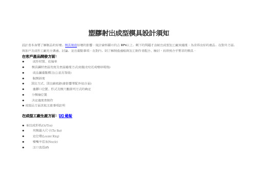
塑膠射出成型模具設計頇知設計者本身要了解制品的好壞﹐模具制造好壞的影響。
統計資料顯示約占80%以上﹐剩下的問題才由射出成型加工廠來處理。
為求得良好的產品﹐在對外方面﹐與客戶及成形工廠充分溝通﹑討論﹐定出重點事項。
在對內﹐則了解制造過程與加工制作者配合﹑檢討,而得到合乎要求的模具。
在客戶產品開發方面﹕●成形材質﹑收縮率● 模具鋼材表面亮度及表面處理方式(如拋光咬花或噴砂規格)●成品圖重點標注(公差及等級)●脫模斜度●頂出方式﹑頂出銷痕跡(會影響零配件組合面)●進膠口位置﹑形式及模穴數排列方式的确定● 分模線位置● 決定進度表制作●成型品方面其他注意事項註明在成型工廠生產方面﹕UG论坛●射出成形机(Oz/Ton)●夾模最大尺寸(Tie Bar)●定位環(Locator Ring)●噴嘴半徑R(Nozzle)●注口直徑(Ø)●模具最小與最大厚度●頂出孔(Ø)●提供流道形式﹑澆口形式﹑頂出方式等資料。
●冷卻方式(水嘴形式)●射出成形生產方面其他註經過上述討論﹑溝通之后﹐再將所得資料帶回﹐和制造加工單位檢討模具設計內容﹐滿足需求。
列出要具制造加工進度表以供追查UG模具設計之程序說明﹕●模穴布局●公母模分模面方向決定●模具及成品尺寸公差●使用鋼材選定●流道﹑澆口﹑頂出位置●冷卻水路方式●低陷處理(Under-cut)●成品頂出方式(如頂出中板﹑套筒頂出)●開模順序﹑距离(Stroke)● 省時﹑省事的方向﹐考慮公模仁(Core Insert)母模仁(Cavity Insert)的鑲嵌模具加工方式●其他如模溫控制﹑冰凍水冷卻等。
五金模具设计手册
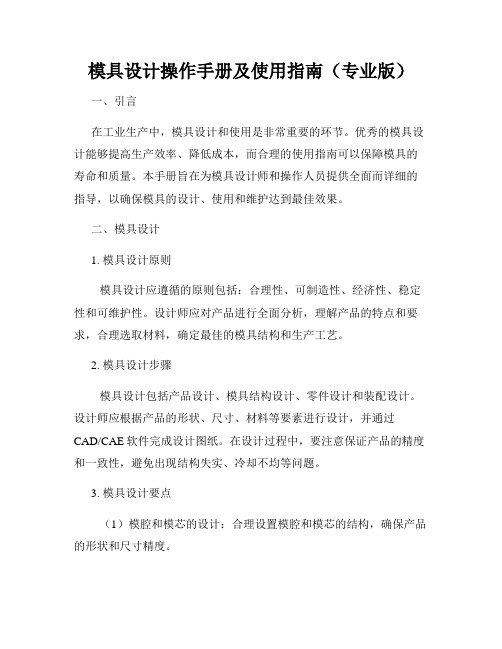
90.0° A
T /4 T
中性層
计 =0.4T
设 4.2 R=0, θ =90°
经验值参考:
(T≧1.2,含 1.2mm)
T=1.2 T=1.5
(K=0.45) L=0.45T (K=0.50) L=0.50T
T>=1.2m m
B
T=2.0 T=3.0
(K=0.55) L=0.55T (K=0.58) L=0.58T
3) 冲裁件的凸出和凹入部分的宽度不宜过小,避免过长的悬臂
和窄槽。
4) 冲裁件上孔的最小尺寸不能太小,否则会导致凸模的折断,
各种材质下一般冲模的最小孔尺寸见表 2-1。
册 表 2-1 最小孔尺寸
手 材料
凸模无导向
凸模精密导向
计 硬钢
圆形 1.3t
矩形 1.0t
圆形 0.5t
矩形 0.4t
设软钢及黄铜
模具设计检点事项
70
第十三节:
模具的试冲与调整
72
第十四节:
冲压工序术语
78
第十五节:
常见模具名称中英文对照表
82
2
一:目的
1. 为模具开发单位提供和补充基本的技术规范,减少或杜绝设计缺
陷造成模具的先天不足.
2. 推行设计标准化,降低设计错误率,实现模具设计快速作业。
3. 保证模具导入后生产出合乎质量要求的产品.
二 工艺性分析
剑
根据产品零件的形状尺寸、材料、精度等要求,对冲压工艺方案
文 设计中所确定的各项工序内容逐一进行分析计算,确定它们对冲压工 杨 艺的适应性。
三 工艺计算
为了进行模具设计和冲压加工,工艺计算首先应根据产品零件的
模具设计手册

第一节 第二节 第二章 第一节 第二节 第三节 第四节 第三章 第一节 第二节 第三节 第四章 第一节 第二节 第三节 第五章 第一节 第二节 第三节 第四节
模具的构造与组成 ………………………………………………………( $ )
模具设计与制造的基本要求 ……………………………………………(&#)
模具设计的一般原则 ……………………………………………………(#()
凸模 …………………………………………………………………(!$%)
冷节 第三节 第四节 第五节 第六节 第七节 第八节
凹模 …………………………………………………………………(!$!) 卸料板 ………………………………………………………………("&&) 导板 …………………………………………………………………("&’) 压料装置 ……………………………………………………………("&$) 导料装置 ……………………………………………………………("%() 挡料和导正装置 ……………………………………………………("%’) 定位与出件装置 ……………………………………………………("(()
………………………………………………(%%&) ………………………………………………(%%")
第二章 第一节 第二节 第三节 第三章 第一节 第二节 第三节 第四章 第一节 第二节 第三节 第四节 第五章 第一节 第二节 第三节 第四节 第五节 第六节 第七节 第八节 第六章 第一节 第二节 第三节 第七章 第一节 第二节 ・$・
…………………………………………………(%$$)
模具对材料的性能要求 ………………………………………………(%$$) 模具常用材料 ………………………………………………………(%$’) 模具选材原则 ………………………………………………………(%($) 冷作模具钢及其热处理 冷作模具钢的热处理 冷作模具钢的性能 热作模具钢及其热处理
模具设计说明书
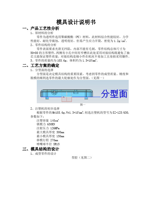
模具设计说明书一、产品工艺性分析1、原材料的分析零件为透明件选用聚碳酸酯(PC)材料,此材料综合性能较好,力学性能好,耐化学腐蚀,透明度好,但易产生应力开裂,密度为1.2g/cm3。
2、零件结构的分析零件表面要求光滑无凹陷,内部不能有毛刺,零件结构总体尺寸为50*80的方形塑件,两侧有小孔中间有窄槽在此处采用对接结构既避免了抽芯又能保证塑件质量,对接结构是细小件在机床不易加工且易损采用镶件。
3、零件的质量约为103.6g,体积约为1.3*104mm3。
二、工艺方案的确定1、分型面的选择分型面是决定模具结构的重要因素,考虑到零件的成型质量、精度和脱模的顺利选零件的最大轮廓处作为分型面。
(见图一)图一2、注塑机的初步选择根据零件的M=103.6g,V=1.3*104mm3,初选注塑机的型号为SZ-125/630,参数如下:注塑容量 140cm3锁模力 630KN注射压力 126MPa最大模具厚度 300mm最小模具厚度 150mm移模行程 270mm喷嘴球半径 SR15三、模具结构的设计1、成型零件的设计型腔(见图二)图二型芯(见图三)图三2、推出机构的选择零件为透明件考虑到成型的表面质量选用推件板推出和Φ8的拉料杆拉出。
3、浇注系统的确定主流道采用Φ12的浇口套,分流道在型腔侧采用R4的半圆,浇口采用5*3*1的侧浇口 4、冷却系统的确定冷却系统的精确计算很难,实际生产中根据模具结构确定冷却回路,通过调节流量来满足要求。
5、排气系统的确定利用分型面和镶件的配合间隙进行排气。
6、模架的确定根据型腔的尺寸大小选用LKM-SG2025BI 的模架四、装配图(见图四)图四五、注塑机的校核经计算型号为SZ-125/630的注塑机提供的性能能满足LKM-SG2025BI 模架的需求。
六、模具工作原理合模——注射座前进——注射——保压补缩——冷却定型(预塑)——开模——制件顶出——合模。
模具设计操作手册及使用指南(专业版)
模具设计操作手册及使用指南(专业版)一、引言在工业生产中,模具设计和使用是非常重要的环节。
优秀的模具设计能够提高生产效率、降低成本,而合理的使用指南可以保障模具的寿命和质量。
本手册旨在为模具设计师和操作人员提供全面而详细的指导,以确保模具的设计、使用和维护达到最佳效果。
二、模具设计1. 模具设计原则模具设计应遵循的原则包括:合理性、可制造性、经济性、稳定性和可维护性。
设计师应对产品进行全面分析,理解产品的特点和要求,合理选取材料,确定最佳的模具结构和生产工艺。
2. 模具设计步骤模具设计包括产品设计、模具结构设计、零件设计和装配设计。
设计师应根据产品的形状、尺寸、材料等要素进行设计,并通过CAD/CAE软件完成设计图纸。
在设计过程中,要注意保证产品的精度和一致性,避免出现结构失实、冷却不均等问题。
3. 模具设计要点(1)模腔和模芯的设计:合理设置模腔和模芯的结构,确保产品的形状和尺寸精度。
(2)冷却系统设计:合理设置冷却通道,确保塑料制品的冷却均匀,提高生产效率和产品质量。
(3)排气系统设计:设置合理的排气通道,排除气泡,避免产品出现缺陷。
(4)脱模机构设计:根据产品特点设计合适的脱模机构,保证产品脱模平稳。
(5)模具表面处理:根据产品要求选择适当的表面处理方法,提高产品的外观和质感。
三、模具使用指南1. 模具安装和调试(1)模具安装:确保模具安装平稳,与生产设备完全配合,避免安装不当导致的事故。
(2)调试过程:根据产品要求进行合理的调试,包括调整模具温度、调节注塑机参数等。
2. 模具使用操作(1)操作规范:操作人员应严格按照操作规范进行操作,确保操作安全。
(2)模具保养:根据使用情况进行定期保养,清洁模具,涂抹防锈剂,防止生锈和损坏。
(3)异常情况处理:当发现模具异常情况时,及时报修或维护,以确保生产的连续性和正常进行。
3. 模具维护(1)日常维护:定期对模具进行检查,检查模具的损坏情况,及时更换损坏部件,确保模具的正常使用。
模具设计说明书
模具设计说明书模具设计说明书1. 引言本文档旨在详细说明模具设计的过程和要求。
模具是用于制造产品的工具或模板,常用于塑料制品、金属制品以及其他各种制造行业。
合理的模具设计能够提高产品的生产效率和质量,降低生产成本。
2. 设计目标模具设计的主要目标是满足产品设计的要求并具备可生产性。
以下是设计模具时需要考虑的主要因素:- 产品设计要求:模具设计必须满足产品的尺寸、形状、质量、表面光洁度等设计要求。
- 材料选择:根据产品的材料特性和生产要求,选择适合的材料制作模具,如钢材、铝材等。
- 成本控制:考虑模具制造成本,选择经济实用的设计方案,尽量减少材料浪费和加工成本。
- 生产效率:模具设计应考虑生产工艺的合理性,能够提高生产效率和产量。
3. 模具设计流程以下是一般模具设计的基本流程:1. 确定产品需求:根据产品设计要求,了解产品的尺寸、形状、材料等信息。
2. 分析产品结构:对产品进行结构分析,确定模具的类型和结构形式,如单腔模具、多腔模具、滑动模具等。
3. 设计模具零件:根据产品的形状和要求,设计模具的各个零件,包括模具座、模腔、模芯、导柱、导套、顶针等。
4. 确定模具材料:根据产品的要求和生产需求,选择适合的模具材料,如有色金属、热处理钢材等。
5. 模具总装:将各个模具零件装配起来,并进行调整和测试,确保各个零部件的配合精度和正常工作。
6. 模具试产:对设计完成的模具进行试产,检验模具的性能和产品质量,进行必要的调整和改进。
7. 模具维护:定期对模具进行维护和保养,延长模具的使用寿命,保证产品质量和生产效率。
4. 模具设计要点在模具设计过程中,需要注意以下要点:4.1. 料斗设计对于塑料制品模具,料斗的设计尤为重要。
料斗的形状和尺寸会直接影响注塑过程中的塑料流动和充填情况。
因此,需要根据塑料流动性和产品形状,设计合适的料斗结构和导向角度,以确保塑料的均匀充填和充实度。
4.2. 排气设计在注塑过程中,空气可能会被困在模具腔中,导致产品气泡和缺陷。
模具设计说明书
模具设计说明书模具设计说明书一、设计要求1.1 目标本文档旨在提供一个详细的模具设计说明,确保模具制造过程中的准确性和一致性。
1.2 范围本文档适用于模具设计团队,旨在指导他们在设计过程中考虑所有必要的因素。
二、设计流程2.1 需求分析2.1.1 目标产品描述描述目标产品的尺寸、形状、材料等基本特征。
2.1.2 模具用途说明模具的具体用途以及所需功能。
2.1.3 生产量要求确定目标产品的预计生产量以及需求的时间表。
2.2 概念设计2.2.1 初步设计方案根据需求分析阶段得出的目标产品要求,提出一个初步的设计方案。
2.2.2 验证与修改对初步设计方案进行验证,通过模拟或其他方法确定其可行性并根据验证结果进行修改。
2.3 详细设计2.3.1 结构设计根据概念设计方案,详细设计模具的整体结构,确保模具的稳定性和耐用性。
2.3.2 零部件设计对模具的各个零部件进行详细设计,包括形状、尺寸、材料等。
2.3.3 流程设计设计模具加工的详细流程,包括材料加工、装配过程等。
2.4 制造与组装2.4.1 材料采购根据设计要求,采购所需的材料,确保其质量和符合设计要求。
2.4.2 加工制造按照流程设计,将所需材料进行加工制造,包括切割、锻造、铣削等工艺。
2.4.3 零部件装配将加工好的零部件进行装配,确保模具的功能性和完整性。
2.5 试模与调试2.5.1 初步试模进行初步试模,验证模具的设计是否符合预期功能,并进行必要的调整。
2.5.2 细致试模对初步试模的结果进行细致检查,调整模具的细节,确保目标产品的质量和精度。
三、附件本文档涉及的附件包括但不限于:- 模具设计图纸- 模具加工流程图- 材料采购清单附件详细内容可根据具体情况进行调整。
四、法律名词及注释- 模具:用于制造特定产品的工具或设备。
- 设计:根据特定目标和要求制定方案或计划的过程。
- 需求分析:对目标产品需求进行详细分析和理解的过程。
模具设计标准手册内容有哪些
模具设计标准手册内容有哪些模具设计标准手册是指用于规范和指导模具设计工作的一本参考手册,它包含了模具设计的基本原则、规范、技术要求等内容。
下面是模具设计标准手册的主要内容:1. 术语和定义:介绍模具设计中常用的术语和定义,确保设计人员对术语的理解一致。
2. 设计原则和规范:包括模具设计的一般原则、设计的基本步骤、设计过程中需要注意的事项等,以确保设计质量和效率。
3. 材料选择和规范:介绍了模具设计中常用的材料,包括金属材料、非金属材料等,以及相应的材料规范和性能要求。
4. 零件设计规范:包括模具零件的设计规范,如尺寸、公差、形位公差等,以确保模具零件的质量和精度要求。
5. 图样和图纸标准:介绍了模具设计中常用的图样和图纸标准,包括符号、线型、尺寸标注等,以确保设计图纸的规范和统一。
6. 加工工艺和工艺设备:介绍了模具加工的常用工艺和设备,包括数控加工、装配工艺等,以确保加工质量和效率。
7. 模具试验和调试:介绍了模具试验和调试的基本步骤和方法,包括模具装配、试运转等,以确保模具在正式投产前能够正常工作。
8. 安全和环保要求:介绍了模具设计中需要遵守的安全和环保要求,包括安全操作规程、废料处理等,以确保设计过程中的安全和环保。
9. 质量控制和检验:介绍了模具设计中的质量控制和检验方法,包括尺寸检测、材料检验等,以确保设计结果符合要求。
10. 标准件和购买规范:介绍了模具设计中常用的标准件,包括标准模组、标准零部件等,以及相应的购买规范和注意事项。
综上所述,模具设计标准手册内容包括了术语和定义、设计原则和规范、材料选择和规范、零件设计规范、图样和图纸标准、加工工艺和工艺设备、模具试验和调试、安全和环保要求、质量控制和检验、标准件和购买规范等内容,这些内容的目的是为了规范和指导模具设计工作的进行,以提高设计质量和效率,确保模具能够满足使用要求。
SOLIDWORKS 模具设计用户指南说明书
SOLIDWORKSMold Design Using SOLIDWORKS Dassault Systèmes SolidWorks Corporation175 Wyman StreetWaltham, MA 02451 U.S.A.© 1995-2022, Dassault Systemes SolidWorks Corporation, a Dassault Systèmes SE company, 175 Wyman Street, Waltham, Mass. 02451 USA. All Rights Reserved.The information and the software discussed in this document are subject to change without notice and are not commitments by Dassault Systemes SolidWorks Corporation (DS SolidWorks).No material may be reproduced or transmitted in any form or by any means, electronically or manually, for any purpose without the express written permission of DS SolidWorks.The software discussed in this document is furnished under a license and may be used or copied only in accordance with the terms of the license. All warranties given by DS SolidWorks as to the software and documentation are set forth in the license agreement, and nothing stated in, or implied by, this document or its contents shall be considered or deemed a modification or amendment of any terms, including warranties, in the license agreement.For a full list of the patents, trademarks, and third-party software contained in this release, please go to the Legal Notices in the SOLIDWORKS documentation.Restricted RightsThis clause applies to all acquisitions of Dassault Systèmes Offerings by or for the United States federal government, or by any prime contractor or subcontractor (at any tier) under any contract, grant, cooperative agreement or other activity with the federal government. The software, documentation and any other technical data provided hereunder is commercial in nature and developed solely at private expense. The Software is delivered as "Commercial Computer Software" as defined in DFARS 252.227-7014 (June 1995) or as a "Commercial Item" as defined in FAR 2.101(a) and as such is provided with only such rights as are provided in Dassault Systèmes standard commercial end user license agreement. Technical data is provided with limited rights only as provided in DFAR 252.227-7015 (Nov. 1995) or FAR 52.227-14 (June 1987), whichever is applicable. The terms and conditions of the Dassault Systèmes standard commercial end user license agreement shall pertain to the United States government's use and disclosure of this software, and shall supersede any conflicting contractual terms and conditions. If the DS standard commercial license fails to meet the United States government's needs or is inconsistent in any respect with United States Federal law, the United States government agrees to return this software, unused, to DS. The following additional statement applies only to acquisitions governed by DFARS Subpart 227.4 (October 1988): "Restricted Rights - use, duplication and disclosure by the Government is subject to restrictions as set forth in subparagraph (c)(l)(ii) of the Rights in Technical Data and Computer Software clause at DFARS 252-227-7013 (Oct. 1988)."In the event that you receive a request from any agency of the U.S. Government to provide Software with rights beyond those set forth above, you will notify DS SolidWorks of the scope of the request and DS SolidWorks will have five (5) business days to, in its sole discretion, accept or reject such request. Contractor/ Manufacturer: Dassault Systemes SolidWorks Corporation, 175 Wyman Street, Waltham, Massachusetts 02451 USA.Document Number: PMT2305-ENGContents IntroductionAbout This Course . . . . . . . . . . . . . . . . . . . . . . . . . . . . . . . . . . . . . . . . 2Prerequisites . . . . . . . . . . . . . . . . . . . . . . . . . . . . . . . . . . . . . . . . . . 2Course Design Philosophy . . . . . . . . . . . . . . . . . . . . . . . . . . . . . . . 2Using this Book . . . . . . . . . . . . . . . . . . . . . . . . . . . . . . . . . . . . . . . . . . 2Laboratory Exercises . . . . . . . . . . . . . . . . . . . . . . . . . . . . . . . . . . . 3A Note About Dimensions . . . . . . . . . . . . . . . . . . . . . . . . . . . . . . . 3Conventions Used in this Book . . . . . . . . . . . . . . . . . . . . . . . . . . . 3About the Training Files. . . . . . . . . . . . . . . . . . . . . . . . . . . . . . . . . 3Training Templates. . . . . . . . . . . . . . . . . . . . . . . . . . . . . . . . . . . . . 4Windows. . . . . . . . . . . . . . . . . . . . . . . . . . . . . . . . . . . . . . . . . . . . . . . . 4Use of Color . . . . . . . . . . . . . . . . . . . . . . . . . . . . . . . . . . . . . . . . . . . . . 5Color Schemes . . . . . . . . . . . . . . . . . . . . . . . . . . . . . . . . . . . . . . . . 5SOLIDWORKS Plastics. . . . . . . . . . . . . . . . . . . . . . . . . . . . . . . . . . . . 6More SOLIDWORKS Training Resources. . . . . . . . . . . . . . . . . . . . . . 6Local User Groups . . . . . . . . . . . . . . . . . . . . . . . . . . . . . . . . . . . . . 6 Lesson 1Surface Concepts and Imported GeometryCourse Overview . . . . . . . . . . . . . . . . . . . . . . . . . . . . . . . . . . . . . . . . . 8Surfaces in Mold Design. . . . . . . . . . . . . . . . . . . . . . . . . . . . . . . . . . . . 83D Model Types . . . . . . . . . . . . . . . . . . . . . . . . . . . . . . . . . . . . . . . . . . 9Wireframe Models . . . . . . . . . . . . . . . . . . . . . . . . . . . . . . . . . . . . . 9Surface Models. . . . . . . . . . . . . . . . . . . . . . . . . . . . . . . . . . . . . . . . 9Solid Models. . . . . . . . . . . . . . . . . . . . . . . . . . . . . . . . . . . . . . . . . . 9Geometry vs Topology . . . . . . . . . . . . . . . . . . . . . . . . . . . . . . . . . . . . . 9What is a Solid? . . . . . . . . . . . . . . . . . . . . . . . . . . . . . . . . . . . . . . 11Euler’s Formula . . . . . . . . . . . . . . . . . . . . . . . . . . . . . . . . . . . . . . 11iContents SOLIDWORKSii Behind the Scenes. . . . . . . . . . . . . . . . . . . . . . . . . . . . . . . . . . . . . . . . 12 Adjusting FeatureManager Settings . . . . . . . . . . . . . . . . . . . . . . . 12 Extruded Surface. . . . . . . . . . . . . . . . . . . . . . . . . . . . . . . . . . . . . . 13 Turning on the Surfaces Toolbar . . . . . . . . . . . . . . . . . . . . . . . . . 13 Planar Surface. . . . . . . . . . . . . . . . . . . . . . . . . . . . . . . . . . . . . . . . 14 Trim Surface. . . . . . . . . . . . . . . . . . . . . . . . . . . . . . . . . . . . . . . . . 15 Untrim Surface . . . . . . . . . . . . . . . . . . . . . . . . . . . . . . . . . . . . . . . 17 Face Curves and Mesh Preview . . . . . . . . . . . . . . . . . . . . . . . . . . 17 Surface Types. . . . . . . . . . . . . . . . . . . . . . . . . . . . . . . . . . . . . . . . 18 Four-Sided Surfaces . . . . . . . . . . . . . . . . . . . . . . . . . . . . . . . . . . . 20 Knit Surface . . . . . . . . . . . . . . . . . . . . . . . . . . . . . . . . . . . . . . . . . 21 Gap Control. . . . . . . . . . . . . . . . . . . . . . . . . . . . . . . . . . . . . . . . . . 21 Creating Solids from Surfaces . . . . . . . . . . . . . . . . . . . . . . . . . . . . . . 22 Create Solid. . . . . . . . . . . . . . . . . . . . . . . . . . . . . . . . . . . . . . . . . . 22 Thicken. . . . . . . . . . . . . . . . . . . . . . . . . . . . . . . . . . . . . . . . . . . . . 22 Summary. . . . . . . . . . . . . . . . . . . . . . . . . . . . . . . . . . . . . . . . . . . . 23 Decomposing a Solid into Surfaces . . . . . . . . . . . . . . . . . . . . . . . . . . 23 Delete Face. . . . . . . . . . . . . . . . . . . . . . . . . . . . . . . . . . . . . . . . . . 23 Additional Surface Concepts . . . . . . . . . . . . . . . . . . . . . . . . . . . . . . . 25 Boolean Operations. . . . . . . . . . . . . . . . . . . . . . . . . . . . . . . . . . . . 25 Edges vs. Holes. . . . . . . . . . . . . . . . . . . . . . . . . . . . . . . . . . . . . . . 25 Surfaces Concepts Takeaways . . . . . . . . . . . . . . . . . . . . . . . . . . . . . . 26 Importing and Mold Design . . . . . . . . . . . . . . . . . . . . . . . . . . . . . . . . 26 Modeling Kernels. . . . . . . . . . . . . . . . . . . . . . . . . . . . . . . . . . . . . 26 Contents of a CAD File . . . . . . . . . . . . . . . . . . . . . . . . . . . . . . . . 27 File Formats . . . . . . . . . . . . . . . . . . . . . . . . . . . . . . . . . . . . . . . . . 27 Format Recommendations . . . . . . . . . . . . . . . . . . . . . . . . . . . . . . 28 File Translation. . . . . . . . . . . . . . . . . . . . . . . . . . . . . . . . . . . . . . . . . . 29 Why Do Imports Fail? . . . . . . . . . . . . . . . . . . . . . . . . . . . . . . . . . . . . 29 SOLIDWORKS Import Options. . . . . . . . . . . . . . . . . . . . . . . . . . . . . 30 3D Interconnect for Native File Formats . . . . . . . . . . . . . . . . . . . 30 3D Interconnect for Neutral File Formats. . . . . . . . . . . . . . . . . . . 31 Case Study: Importing a STEP File . . . . . . . . . . . . . . . . . . . . . . . . . . 31 Import Diagnostics . . . . . . . . . . . . . . . . . . . . . . . . . . . . . . . . . . . . 33 Addressing Errors in 3D Interconnect Imports. . . . . . . . . . . . . . . 34 Another Option. . . . . . . . . . . . . . . . . . . . . . . . . . . . . . . . . . . . . . . 35 Comparing Geometry. . . . . . . . . . . . . . . . . . . . . . . . . . . . . . . . . . . . . 37 Addressing Translation Errors . . . . . . . . . . . . . . . . . . . . . . . . . . . . . . 39 Repairing and Editing Imported Geometry . . . . . . . . . . . . . . . . . . . . 39 Check Entity. . . . . . . . . . . . . . . . . . . . . . . . . . . . . . . . . . . . . . . . . 40 Display Curvature. . . . . . . . . . . . . . . . . . . . . . . . . . . . . . . . . . . . . 42 Patching Strategies . . . . . . . . . . . . . . . . . . . . . . . . . . . . . . . . . . . . 43 Filled Surface . . . . . . . . . . . . . . . . . . . . . . . . . . . . . . . . . . . . . . . . 44 Another Strategy. . . . . . . . . . . . . . . . . . . . . . . . . . . . . . . . . . . . . . 46SOLIDWORKS ContentsProcedure for Rebuilding Fillets. . . . . . . . . . . . . . . . . . . . . . . . . . . . . 48Making Copies of Faces. . . . . . . . . . . . . . . . . . . . . . . . . . . . . . . . 48Offset Surface. . . . . . . . . . . . . . . . . . . . . . . . . . . . . . . . . . . . . . . . 48Extend Surface . . . . . . . . . . . . . . . . . . . . . . . . . . . . . . . . . . . . . . . 50Editing Imported Parts . . . . . . . . . . . . . . . . . . . . . . . . . . . . . . . . . 52Delete Hole. . . . . . . . . . . . . . . . . . . . . . . . . . . . . . . . . . . . . . . . . . 53Exercise 1: Import Diagnosis . . . . . . . . . . . . . . . . . . . . . . . . . . . . . . . 55Exercise 2: Using Import Surface and Replace Face . . . . . . . . . . . . . 58 Lesson 2Core and CavityCore and Cavity Mold Design . . . . . . . . . . . . . . . . . . . . . . . . . . . . . . 62Steps in the Mold Design Process. . . . . . . . . . . . . . . . . . . . . . . . . 62Summary of Steps. . . . . . . . . . . . . . . . . . . . . . . . . . . . . . . . . . . . . 64SOLIDWORKS Mold Tools. . . . . . . . . . . . . . . . . . . . . . . . . . . . . . . . 64Case Study: Camera Body . . . . . . . . . . . . . . . . . . . . . . . . . . . . . . . . . 64Mold Analysis Tools. . . . . . . . . . . . . . . . . . . . . . . . . . . . . . . . . . . . . . 65GPU-based Processing . . . . . . . . . . . . . . . . . . . . . . . . . . . . . . . . . 65Analyzing Draft on a Model. . . . . . . . . . . . . . . . . . . . . . . . . . . . . . . . 65What is Draft?. . . . . . . . . . . . . . . . . . . . . . . . . . . . . . . . . . . . . . . . 65Determining the Direction of Pull . . . . . . . . . . . . . . . . . . . . . . . . 66Using the Draft Analysis Tool . . . . . . . . . . . . . . . . . . . . . . . . . . . . . . 66Positive and Negative Draft . . . . . . . . . . . . . . . . . . . . . . . . . . . . . 68Requires Draft. . . . . . . . . . . . . . . . . . . . . . . . . . . . . . . . . . . . . . . . 68Draft Analysis Options . . . . . . . . . . . . . . . . . . . . . . . . . . . . . . . . . . . . 68Gradual Transition . . . . . . . . . . . . . . . . . . . . . . . . . . . . . . . . . . . . 68Face Classification . . . . . . . . . . . . . . . . . . . . . . . . . . . . . . . . . . . . 69Find Steep Faces. . . . . . . . . . . . . . . . . . . . . . . . . . . . . . . . . . . . . . 69Adding Draft. . . . . . . . . . . . . . . . . . . . . . . . . . . . . . . . . . . . . . . . . . . . 70Scaling the Model. . . . . . . . . . . . . . . . . . . . . . . . . . . . . . . . . . . . . . . . 72Establish the Parting Lines. . . . . . . . . . . . . . . . . . . . . . . . . . . . . . . . . 73Parting Lines Options. . . . . . . . . . . . . . . . . . . . . . . . . . . . . . . . . . 73Manual Parting Lines . . . . . . . . . . . . . . . . . . . . . . . . . . . . . . . . . . 75Shut-Off Surfaces . . . . . . . . . . . . . . . . . . . . . . . . . . . . . . . . . . . . . . . . 75Shut-off Surface Patch Types. . . . . . . . . . . . . . . . . . . . . . . . . . . . 75Manual Shut-off Surfaces. . . . . . . . . . . . . . . . . . . . . . . . . . . . . . . 77Creating the Parting Surface. . . . . . . . . . . . . . . . . . . . . . . . . . . . . . . . 77Parting Surfaces Options . . . . . . . . . . . . . . . . . . . . . . . . . . . . . . . 78Smoothing the Parting Surface. . . . . . . . . . . . . . . . . . . . . . . . . . . 80Surface Bodies . . . . . . . . . . . . . . . . . . . . . . . . . . . . . . . . . . . . . . . . . . 82Creating the Mold Tooling . . . . . . . . . . . . . . . . . . . . . . . . . . . . . . . . . 83Tooling Split. . . . . . . . . . . . . . . . . . . . . . . . . . . . . . . . . . . . . . . . . 83Seeing Inside the Mold. . . . . . . . . . . . . . . . . . . . . . . . . . . . . . . . . . . . 85Interlocking the Mold Tooling . . . . . . . . . . . . . . . . . . . . . . . . . . . . . . 86Creating Interlock Surfaces . . . . . . . . . . . . . . . . . . . . . . . . . . . . . 86Creating Part and Assembly Files. . . . . . . . . . . . . . . . . . . . . . . . . . . . 88Completing the Mold . . . . . . . . . . . . . . . . . . . . . . . . . . . . . . . . . . 89iiiContents SOLIDWORKSiv Exercise 3: Casting. . . . . . . . . . . . . . . . . . . . . . . . . . . . . . . . . . . . . . . 90 Exercise 4: Ribbed Part. . . . . . . . . . . . . . . . . . . . . . . . . . . . . . . . . . . . 94 Exercise 5: Dustpan . . . . . . . . . . . . . . . . . . . . . . . . . . . . . . . . . . . . . . 97Lesson 3Side Cores and PinsAdditional Mold Tooling . . . . . . . . . . . . . . . . . . . . . . . . . . . . . . . . . 110Additional Tooling Design Process . . . . . . . . . . . . . . . . . . . . . . 110Case Study: Power Saw Housing . . . . . . . . . . . . . . . . . . . . . . . . . . . 111Thickness Analysis. . . . . . . . . . . . . . . . . . . . . . . . . . . . . . . . . . . 112Detecting Undercuts. . . . . . . . . . . . . . . . . . . . . . . . . . . . . . . . . . 114Undercut Analysis. . . . . . . . . . . . . . . . . . . . . . . . . . . . . . . . . . . . 114Trapped Molding Areas . . . . . . . . . . . . . . . . . . . . . . . . . . . . . . . . . . 116Side Cores. . . . . . . . . . . . . . . . . . . . . . . . . . . . . . . . . . . . . . . . . . . . . 116Core Feature . . . . . . . . . . . . . . . . . . . . . . . . . . . . . . . . . . . . . . . . 116Feature Freeze. . . . . . . . . . . . . . . . . . . . . . . . . . . . . . . . . . . . . . . . . . 117Lifters . . . . . . . . . . . . . . . . . . . . . . . . . . . . . . . . . . . . . . . . . . . . . . . . 120Core Pins. . . . . . . . . . . . . . . . . . . . . . . . . . . . . . . . . . . . . . . . . . . . . . 122Manual Selection Techniques. . . . . . . . . . . . . . . . . . . . . . . . . . . . . . 123Selection Tools. . . . . . . . . . . . . . . . . . . . . . . . . . . . . . . . . . . . . . 123The Message Pane . . . . . . . . . . . . . . . . . . . . . . . . . . . . . . . . . . . 124Case Study: Mixer Base . . . . . . . . . . . . . . . . . . . . . . . . . . . . . . . . . . 124Modifying Shut-Off Surfaces. . . . . . . . . . . . . . . . . . . . . . . . . . . . . . 127Manual Shut-Off Surfaces . . . . . . . . . . . . . . . . . . . . . . . . . . . . . 127Manually Selecting Loops . . . . . . . . . . . . . . . . . . . . . . . . . . . . . 128Completing the Tooling . . . . . . . . . . . . . . . . . . . . . . . . . . . . . . . . . . 133Exercise 6: Towing Mirror. . . . . . . . . . . . . . . . . . . . . . . . . . . . . . . . 134Exercise 7: Completing the Mixer Base. . . . . . . . . . . . . . . . . . . . . . 141Exercise 8: Electrode Design . . . . . . . . . . . . . . . . . . . . . . . . . . . . . . 150 Lesson 4Advanced Parting Line OptionsCase Study: Manual Parting Line. . . . . . . . . . . . . . . . . . . . . . . . . . . 158Using Split Faces . . . . . . . . . . . . . . . . . . . . . . . . . . . . . . . . . . . . 159Using Entities to Split. . . . . . . . . . . . . . . . . . . . . . . . . . . . . . . . . 160Case Study: Splitting a Part . . . . . . . . . . . . . . . . . . . . . . . . . . . . . . . 164Creating Ruled Surfaces. . . . . . . . . . . . . . . . . . . . . . . . . . . . . . . 166Exercise 9: Peeler . . . . . . . . . . . . . . . . . . . . . . . . . . . . . . . . . . . . . . . 169 Lesson 5Creating Custom Surfaces for Mold DesignSurface Modeling for Mold Design . . . . . . . . . . . . . . . . . . . . . . . . . 176Case Study: Drill Bezel. . . . . . . . . . . . . . . . . . . . . . . . . . . . . . . . . . . 177Manual Interlock Surfaces . . . . . . . . . . . . . . . . . . . . . . . . . . . . . 178Using Select Partial Loop. . . . . . . . . . . . . . . . . . . . . . . . . . . . . . 179Ruled Surface Direction . . . . . . . . . . . . . . . . . . . . . . . . . . . . . . . 180Problem Areas. . . . . . . . . . . . . . . . . . . . . . . . . . . . . . . . . . . . . . . 182Creating the Parting Surface. . . . . . . . . . . . . . . . . . . . . . . . . . . . 184Organizing Surfaces . . . . . . . . . . . . . . . . . . . . . . . . . . . . . . . . . . 185SOLIDWORKS ContentsCase Study: Router Bottom . . . . . . . . . . . . . . . . . . . . . . . . . . . . . . . 187Manual Parting Surface Techniques. . . . . . . . . . . . . . . . . . . . . . 190Organizing Manual Shut-off Surfaces . . . . . . . . . . . . . . . . . . . . 193Copying Surfaces . . . . . . . . . . . . . . . . . . . . . . . . . . . . . . . . . . . . 193Exercise 10: Power Strip. . . . . . . . . . . . . . . . . . . . . . . . . . . . . . . . . . 196Exercise 11: Router Top. . . . . . . . . . . . . . . . . . . . . . . . . . . . . . . . . . 200 Lesson 6Advanced Surfacing for Mold DesignSurface Modeling for Mold Design . . . . . . . . . . . . . . . . . . . . . . . . . 208The Mixer. . . . . . . . . . . . . . . . . . . . . . . . . . . . . . . . . . . . . . . . . . . . . 208Case Study: Mixer Rear Housing. . . . . . . . . . . . . . . . . . . . . . . . . . . 209Manual Parting Surface . . . . . . . . . . . . . . . . . . . . . . . . . . . . . . . 212Insert Mold Folders. . . . . . . . . . . . . . . . . . . . . . . . . . . . . . . . . . . 216Case Study: Mixer Handle . . . . . . . . . . . . . . . . . . . . . . . . . . . . . . . . 219Manual Shut-off Surfaces. . . . . . . . . . . . . . . . . . . . . . . . . . . . . . 219No Fill Shut-off Surfaces . . . . . . . . . . . . . . . . . . . . . . . . . . . . . . 221Manual Side Cores . . . . . . . . . . . . . . . . . . . . . . . . . . . . . . . . . . . 228Exercise 12: Mixer Switch . . . . . . . . . . . . . . . . . . . . . . . . . . . . . . . . 231Exercise 13: Fan Bezel. . . . . . . . . . . . . . . . . . . . . . . . . . . . . . . . . . . 236 Lesson 7Alternative Methods for Mold DesignAlternate Methods for Mold Design. . . . . . . . . . . . . . . . . . . . . . . . . 248When to use Alternate Methods . . . . . . . . . . . . . . . . . . . . . . . . . 248Using Combine and Split . . . . . . . . . . . . . . . . . . . . . . . . . . . . . . . . . 248Copying Bodies in Place. . . . . . . . . . . . . . . . . . . . . . . . . . . . . . . 250Creating a Cavity . . . . . . . . . . . . . . . . . . . . . . . . . . . . . . . . . . . . . . . 252Case Study: Cavity . . . . . . . . . . . . . . . . . . . . . . . . . . . . . . . . . . . . . . 252Case Study: Using Surfaces . . . . . . . . . . . . . . . . . . . . . . . . . . . . . . . 255Techniques for Mold Tooling . . . . . . . . . . . . . . . . . . . . . . . . . . . . . . 258Using the Up To Surface Method. . . . . . . . . . . . . . . . . . . . . . . . 258Using the Split Method. . . . . . . . . . . . . . . . . . . . . . . . . . . . . . . . 259Exercise 14: Peeler Using Combine. . . . . . . . . . . . . . . . . . . . . . . . . 261Exercise 15: Handle . . . . . . . . . . . . . . . . . . . . . . . . . . . . . . . . . . . . . 265Exercise 16: Filter. . . . . . . . . . . . . . . . . . . . . . . . . . . . . . . . . . . . . . . 269 Lesson 8Reusable DataReusing Data. . . . . . . . . . . . . . . . . . . . . . . . . . . . . . . . . . . . . . . . . . . 280Library Features . . . . . . . . . . . . . . . . . . . . . . . . . . . . . . . . . . . . . 280Smart Components . . . . . . . . . . . . . . . . . . . . . . . . . . . . . . . . . . . 2803DEXPERIENCE Marketplace . . . . . . . . . . . . . . . . . . . . . . . . . 280Task Pane . . . . . . . . . . . . . . . . . . . . . . . . . . . . . . . . . . . . . . . . . . . . . 281SOLIDWORKS Resources. . . . . . . . . . . . . . . . . . . . . . . . . . . . . . . . 281Design Library . . . . . . . . . . . . . . . . . . . . . . . . . . . . . . . . . . . . . . . . . 282Essentials of Using the Design Library . . . . . . . . . . . . . . . . . . . 283Folder Graphics. . . . . . . . . . . . . . . . . . . . . . . . . . . . . . . . . . . . . . 283Main Directory Structure . . . . . . . . . . . . . . . . . . . . . . . . . . . . . . 284vContents SOLIDWORKSvi File Explorer. . . . . . . . . . . . . . . . . . . . . . . . . . . . . . . . . . . . . . . . . . . 286 Library Features . . . . . . . . . . . . . . . . . . . . . . . . . . . . . . . . . . . . . . . . 287 Two Techniques for Locating. . . . . . . . . . . . . . . . . . . . . . . . . . . 287 Case Study: Create A Library Feature . . . . . . . . . . . . . . . . . . . . . . . 287 Library Feature Characteristics. . . . . . . . . . . . . . . . . . . . . . . . . . 291 Organizing Library Feature Part Dimensions. . . . . . . . . . . . . . . 293 Replacing Dimensions . . . . . . . . . . . . . . . . . . . . . . . . . . . . . . . . 293 Renaming Dimensions . . . . . . . . . . . . . . . . . . . . . . . . . . . . . . . . 293 Sorting Dimensions . . . . . . . . . . . . . . . . . . . . . . . . . . . . . . . . . . 294 Configurations in Library Features. . . . . . . . . . . . . . . . . . . . . . . . . . 297 Case Study: Water Line. . . . . . . . . . . . . . . . . . . . . . . . . . . . . . . . . . . 297 Creating Library Features from Existing Parts. . . . . . . . . . . . . . 301 Smart Components . . . . . . . . . . . . . . . . . . . . . . . . . . . . . . . . . . . . . . 301 Create the Defining Assembly . . . . . . . . . . . . . . . . . . . . . . . . . . 301 Make Smart Component. . . . . . . . . . . . . . . . . . . . . . . . . . . . . . . 304 Inserting the Smart Component . . . . . . . . . . . . . . . . . . . . . . . . . 305 Inserting Smart Features. . . . . . . . . . . . . . . . . . . . . . . . . . . . . . . 305 Exercise 17: Smart Components. . . . . . . . . . . . . . . . . . . . . . . . . . . . 309 Exercise 18: Complete Mold Insert Project . . . . . . . . . . . . . . . . . . . 310 Developing a Plan. . . . . . . . . . . . . . . . . . . . . . . . . . . . . . . . . . . . 311 Modeling Repairs . . . . . . . . . . . . . . . . . . . . . . . . . . . . . . . . . . . . 313 Runners and Gates . . . . . . . . . . . . . . . . . . . . . . . . . . . . . . . . . . . 321 Side Cores. . . . . . . . . . . . . . . . . . . . . . . . . . . . . . . . . . . . . . . . . . 322 Ejector Pins. . . . . . . . . . . . . . . . . . . . . . . . . . . . . . . . . . . . . . . . . 327 Core Pins. . . . . . . . . . . . . . . . . . . . . . . . . . . . . . . . . . . . . . . . . . . 328 Creating Individual Parts . . . . . . . . . . . . . . . . . . . . . . . . . . . . . . 331Lesson 9Completing the Mold BaseCase Study: Mold Base. . . . . . . . . . . . . . . . . . . . . . . . . . . . . . . . . . . 334Organizing the Assembly . . . . . . . . . . . . . . . . . . . . . . . . . . . . . . . . . 336Assembly Structure Editing . . . . . . . . . . . . . . . . . . . . . . . . . . . . 336Modifying the Lifters . . . . . . . . . . . . . . . . . . . . . . . . . . . . . . . . . . . . 341Lifter Motion. . . . . . . . . . . . . . . . . . . . . . . . . . . . . . . . . . . . . . . . . . . 343Ejector Pins. . . . . . . . . . . . . . . . . . . . . . . . . . . . . . . . . . . . . . . . . . . . 346Adding the Bezel . . . . . . . . . . . . . . . . . . . . . . . . . . . . . . . . . . . . 347Cooling the Mold . . . . . . . . . . . . . . . . . . . . . . . . . . . . . . . . . . . . . . . 350Making the Drawing. . . . . . . . . . . . . . . . . . . . . . . . . . . . . . . . . . . . . 356Making Changes. . . . . . . . . . . . . . . . . . . . . . . . . . . . . . . . . . . . . . . . 357Completing the Process . . . . . . . . . . . . . . . . . . . . . . . . . . . . . . . . . . 361。