The new Cayenne POS Lauch Event Evaluation Form
Xantrex XDC 6 kW数字控制可编程DC电源说明书

© 2004 Xantrex Technology Inc. All rights reserved. Xantrex is a registered trademark of Xantrex International. DS20040518R03_xdc6kw. Printed in Canada.Xantrex Technology Inc. Headquarters8999 Nelson Way Burnaby, British Columbia Canada V5A 4B5800 670 0707 Toll Free604 420 1591 Fax5916 195th Street NE Arlington, WashingtonUSA 98223800 446 6180 Toll Free360 925 5144 FaxXDC 6 kWProvides 6 kW of DC Power for Test and Measurement ApplicationsThe Xantrex XDC 6 kW digital controlled programmable DC power supply provides clean, reliable powerfor ATE, burn-in, magnet charging, OEM, and other test and measurement applications. With an embeddedcontroller, it has a unique menu-driven auto sequencing capability, which allows for complex test sequences to beentered and saved via the front panel without the need for external computers or software.With the XDC 6 kW, ten different test programs of up to 99 voltage level steps each, can be constructedand executed by a manual or external trigger. This stand-alone capability can be used for constructingsimple voltage ramps, battery charging and simulation of battery voltage at engine start-up, componenttesting, and MIL 704E testing. Additionally, ten configurations of differing protection and output setpoints can also be conveniently stored, recalled, or set for default at start up.The XDC 6 kW comes in a compact 5.25-inch (3U) high rack package and is available in ten models. Itcan also be configured into high power systems of 18 kW, 24 kW, or 30 kW by adding parallel XDC 6kW slave modules that are controlled from a master XDC unit via a CANbus communications link.Product FeaturesEmbedded controllerZero voltage “Soft Switching”Power Factor Correction (PFC)Simultaneous display of output voltage and currentConstant power modeCurrent sharing for parallel operationRemote sense with 5 V line loss compensationRS-232 interfaceLabVIEW® and LabWindows® driversProtection FeaturesOver and under voltage protectionOver and under current protectionOver and under power protectionOver temperature protectionSense protectionOptionsGPIB (IEEE 488.2 with SCPI)CANbus communications link for multiple unit current sharing and addressingHigh voltage input: 3-phase, 342-500 VACXDC 6 kWElectrical Specifi cationsModels10-600 20-300 30-200 40-150 60-100 80-75 100-60 150-40 300-20 600-10 Output RatingsOutput Voltage 10-10 V 0-20 V 0-30 V 0-40 V 0-60 V 0-80 V 0-100 V 0-150 V 0-300 V 0-600 VOutput Current 2 0-600 A 0-300 A 0-200 A 0-150 A 0-100 A 0-75 A 0-60 A 0-40 A 0-20 A 0-10 AOutput Power 6000 W 6000 W6000 W6000 W6000 W6000 W6000 W6000 W6000 W6000 W Line Regulation 3Voltage 1 mV 1 mV 2 mV 2 mV 3 mV 3 mV 3 mV 5 mV 7 mV 10 mVCurrent 150 mA 50 mA 50 mA 30 mA 20 mA 20 mA 20 mA 10 mA 5 mA 5 mA Load Regulation 4Voltage 10 mV 10 mV 10 mV 10 mV 10 mV 10 mV 10 mV 10 mV 15 mV 30 mVCurrent 150 mA 50 mA 50 mA 30 mA 30 mA 20 mA 20 mA 10 mA 10 mA 10 mA Meter AccuracyVoltage (0.15% of Vmax) 15 mV 30 mV 45 mV 60 mV 90 mV 120 mV 150 mV 225 mV 450 mV 900 mVCurrent (0.5% of Imax) 3 A 1.5 A 1 A 750 mA 500 mA 375 mA 300 mA 200 mA 100 mA 50 mA Output Noise (0-20 MHz)Voltage (p-p)85 mV 80 mV 70 mV 70 mV 70 mV75 mV 75 mV 80 mV 80 mV95 mV Output Ripple (rms)Voltage10 mV 10 mV 10 mV 10 mV 10 mV 12 mV 15 mV 15 mV 20 mV 20 mVCurrent 5 500 mA 100 mA 50 mA 50 mA 30 mA 30 mA 30 mA 30 mA 20 mA 20 mA Drift (30 minutes) 6Voltage (0.04% of Vmax) 4 mV 8 mV 12 mV 16 mV 24 mV 32 mV 40 mV 60 mV 120 mV 240 mVCurrent (0.6% of Imax)3600 mA 1800 mA 1200 mA900 mA600 mA450 mA360 mA240 mA120 mA60 mA Drift (8 hours)7Voltage (0.02% of Vmax) 2 mV 4 mV 6 mV 8 mV 12 mV 16 mV 20 mV 30 mV 60 mV 120 mVCurrent (0.04% of Imax)240 mA 120 mA 80 mA 60 mA 40 mA 30 mA 24 mA 16 mA 8 mA 4 mA Temperature Coeffi cient8Voltage (0.04% of Vmax/°C) 4 mV 8 mV 12 mV 16 mV 24 mV 32 mV 40 mV 60 mV 120 mV 240 mVCurrent (0.06% of Imax/°C)360 mA 180 mA 120 mA 90 mA 60 mA 45 mA 36 mA 24 mA 12 mA 6 mA OVP Adjustment Range (0 to 103% of Vmax)0-10.3 V 0-20.6 V 0-30.9 V 0-41.2 V 0-61.8 V 0-82.4 V 0-103 V 0-154.5 V 0-309 V 0-618 V Effi ciency985% 87% 87%87%89%89%90%90%91%91%1. Minimum output voltage is <0.3% of rated voltage at zero output setting.2. Minimum output current is <0.2% of rated current at zero output setting when measured with rated load resistance.3. For input voltage variation over the AC input voltage range, with constant rated load.4. For 0-100% load variation, with constant nominal line voltage.5. Current mode noise is measured from 10% to 100% of rated output voltage, full current, unit in CC mode.6. Maximum drift over 30 minutes with constant line, load, and temperature, after power on.7. Maximum drift over 8 hours with constant line, load, and temperature, after 30 minute warm-up.8. Change in output per °C change in ambient temperature, with constant line and load.9. Typical effi ciency at nominal input voltage and full output power.General Specifi cationsOperational AC Input Voltage3-phase 190-242 VAC (47-63 Hz) (standard); 3-phase 342-500 VAC, 47-63 Hz, 3 wire and safety ground (optional)Power Factor (minimum) 0.95 (nominal 208 Vrms); 0.9 (nominal 400 Vrms HV input option)Remote Analog Programming Voltage and current programming inputs; 0-5 V, 0-10 V (default) voltage sources. Galvanically isolated from supply output.Remote Analog Monitoring Voltage and current monitor outputs 0-5 V, 0-10 V (default) ranges for 0-100% of output. Galvanically isolated from supply output.Dimensions (HxWxD) 5.22 x 19.0 x 21.0” (133 x 483 x 533 mm)Weight Approximately 75 lb (34 kg)Warranty 5 yearsApprovals CE marked units meet: EN61010-1, EN61000-6-2 and EN61000-6-4; CSA C/US certifi ed to UL3111-1 and CSA C22.2 No 1010.1Meets USA EMC standard: FCC, part 15B, class A; Meets Canadian EMC standard: ICES-001 Class A.Note: Specifi cations are subject to change without notice.。
拜迪亚自动洗车系统用户指南说明书

Additional FeaturesADDITIONAL FEATURES HOOD RELEASEThe hood release handle is located below the instrument panel.Pull the handle toward you to release.From the front of your vehicle,release the auxiliary latch under the front center of the hood and lift until the lift cylinders hold it open.POWER WINDOWSPress the bottom portion of the switch to lower;the upper portion to raise.To use the one touch down feature,press the double arrow and release quickly;the window will open fully.Depress again to stop windowoperation.The window lock feature allows only the driver to operate the power windows.Press the left side of the window lock to preventpassengers from lowering power windows;press the right side to restore use of the controls.EXTERIOR MIRRORSPower Side View Mirrors:To adjust these mirrors,select the left arrow to adjust to the left mirror;the right arrow to adjust the right mirror.Move the control in the direction you would like to adjust the mirror.Return to the center position to lock the mirrors in place.Heated Mirrors (If equipped):These mirrors warm up to remove ice,mist and fog when the rear window defrost is activated;attempting to remove ice from these mirrors by hand can damage the glass.Fold-Away Mirrors:Pull the side mirrors in carefully when driving through a narrow space,like an automatic car wash.Ford Motor CompanyCustomer Relationship Center P .O.Box 6248Dearborn,MI 481211-800-392-3673 (FORD)(TDD for the hearing impaired:1-800-232-5952)All information contained in this Mercury Quick Reference Guide was accurate at the time of duplication.We reserve the right to change features,operation and/or functionality of any vehicle specification at any time.Your Mercury dealer is the best source for the most current information.For detailed operating and safety information,please consult your Owner’s Guide.May 2005 First Printing Quick Reference Guide 2006MERCURY GRAND MARQUISQUICK REFERENCE GUIDEMERCURY GRAND MAR QUISLitho in U.S.A.SPECIFICATIONSMessage Center (If equipped)With the ignition in the ON position,the message center (located on your instrument cluster) displays important vehicle information through a constant monitor of vehicle systems.You can select different features for the message center to display by using the message center controls located in the center of the instrument panel.Press the SETUP control to display SYSTEMS CHECK,DISPLAY(odometer/speedometer),FONT SIZE (normal/large),UNITS (english/metric),LANGUAGE,COMPASS ZONE/CALIBRATION,OIL MINDER and START VALUE.Press the SELECT control to select functions in the INFO and SETUP menu.Press the INFO control to display the trip odometer,distance to empty,average fuel economy and the instantaneous fuel economy.Press the RESET control to reset the functions shown in the INFO and SETUP menus.Please refer to your Owner's Guide for complete details on the message center display features.TRUNK RELEASEYour trunk release is located on the trim panel of the driver’s door;press the control to open the trunk.ELECTRONIC COMPASS (If equipped)Located in the overhead console,this compass may be affected when you drive near large buildings,bridges,power lines and powerful broadcastantennas.To make compass adjustments,please consult your Owner’s Guide.POWER SEATS (If equipped)The power seat controls are located inside each front door.Press the top control to tilt the seat back forward or backward.Slide the lower control to move the seat forward or backward.Press either end of the lower control to move the seat cushion up or down.REMOTE ENTRY SYSTEMThe remote entry system allows you to lock or unlock all vehicle doors without a key.Unlocking the doorsPress this control to unlock the driver’s door.The interior lamps will illuminate with the ignition OFF.Press the control a second time within five seconds to unlock all doors.Locking the doorsPress this control to lock all doors.Press again to confirm that all doors are locked.The horn will chirp and the parking lamps and tail lamps will flash.Opening the trunkPress this control once to open the trunk.Sounding the panic alarmThe panic feature operates with the key in the OFF position.Press this control to activate the alarm.To deactivate the alarm,press the control again,or turn the ignition to ACC or ON.CAUTION:Do not use CD with adhesive label**1|VOLUME/POWER CONTROLPress the control to turn the audio system on or off.Turn the control to raise or lower the volume.2|AM/FM AND CDIn radio mode,press AM/FM to select AM,FM1and FM2 frequency bands.In CD mode,press to stop play and begin radio play.Press CD to enter CD mode and to play a CD already in the system.3|SAT AND SCAN/SHUFSCAN/SHUF -Press to hear a brief sampling of all listenable stations in radio mode,or to sample all selections in CD mode.Press again to stop at the desired selection.SHUF -Press and hold to play CD tracks in random order,press again to stop.SAT -SAT is only available when equipped with Satellite radio.Your Audiophile radio comes equipped with Satellite ready capability.The kit to enable Satellite reception is available through your Mercury dealer.Detailed Satellite instructions are included with the dealer installed kit.The dealer installed Satellite kit is available only in the continental United States.4|SEEK FUNCTIONThe SEEK function control works in radio,tape and CD modes.In radio mode,press the left arrow to find the next listenable station down the frequency band;press the right arrow to find the next listenable station up the frequencyband.In tape or CD mode,press the left arrow for the previous selection or track;press the right arrow for the next selection or track.5|TUNE-CATTo move to the next frequency down the radio band,press the left arrow.Press the right arrow to move up the band to the next station;hold the arrow to move quickly through the other stations.6|BASS + TREBLE CONTROLPress the BASS or TREB control,then press the left SEL arrow to decrease the level of BASS or TREB;press the right SEL arrow to increase the level.7|BALANCE + FADEPress BAL and use the left SEL arrow to shift the sound to the left speakers;press the right SEL arrow to shift sound to the right speakers.Press FADE and the right SEL arrow to shift sound to the front speakers;press the left SEL arrow to shift sound to the rear.8|RADIO STATION MEMORY PRESETThese controls can be used to select up to six preset AM stations and twelve FM stations (six in FM1 and six in FM2).Choose the frequency band with the AM/FM select control.Select a station,then press and hold the memory preset control until the sound returns.Your selection will be held in the memory.9|EJECTING THE CDPress this button to stop and eject a CD.For more detailed information on the functions of this audio system,please consult your Owner's Guide.*If your Grand Marquis is equipped with an AM/FM stereo with cassette radio,please consult your Owner’s Guide for more detailed information.** CDs with adhesive labels and irregularly shaped CDs may get stuck in the CD player.Homemade CDs should be identified with permanent felt tip marker rather than adhesive labels.Premium/Audiophile AM/FM StereoIn-Dash Six CD Sound System (If equipped*)MODEL YEAR2006GRAND MARQUISQUICK REFERENCE GUIDE45672398881ROADSIDE ASSISTANCEDuring your vehicle’s 3-year/36,000-mile limited warranty period,every new Mercury vehicle includes the assurance and support of a 24-hour emergency Roadside Assistance program.Roadside Assistance includes such services as fuel delivery,tire changes,jump starts,and help when you are locked out of your vehicle.Please complete your Roadside Assistance identification card and keep it in your wallet for quick reference.This card can be found in your glove compartment,in your Mercury Owner's Guide portfolio.FUEL PUMP SHUT-OFF SWITCHIf you’re involved in a collision and attempt to restart your vehicle,your engine may crank but not start.That may mean the fuel shut-off switch has been activated.You’ll find the switch on the left side of the trunk,behind the left rear tail light and the trunk liner.For information on resetting,please consult your Owner’s Guide.All information contained in this Mercury Quick Reference Guide was accurate at the time ofduplication.We reserve the right to change features,operation and/or functionality of any vehicle specification at any time.Your Mercury dealer is the best source for the most current information.For detailed operating and safety information,please consult your Owner’s Guide.LOCATION OF THE SPARE TIRE AND JACKYour vehicle will be equipped with either a full-size spare or a temporary spare.The temporary spare is smaller than a regular tire and designed for emergency use only.Either spare will be located on a shelf in the trunk,just under the rear window.The jack may be located behind the mini spare tire or behind the full size spare tire.FUSESIf electrical components in your vehicle are not working,a fuse may have blown.Blown fuses are identified by a broken wire within the fuse.To learn about changing fuses,please consult your Owner’s Guide for details.UNLEADED FUEL RECOMMENDATIONSUse “Regular”unleaded gasoline with an(R+M)/2 octane rating of 87.Mercury does not recommend using “Regular”gasoline with an octane rating of 86 or lower in high altitude areas.TIRE PRESSUREAdjust the tire pressure to the recommended specifications found on the Certification label.When checking pressure,use an accurate tire pressure gauge.Check tire pressure when the tires are cold,after the vehicle has been parked for at least one hour or has been driven less than 1 mile (1.6 km).Warning:Improperlyinflated tires can affect vehicle handling and can fail suddenly,possibly resulting in loss of vehicle control.6W3J-19G217-AA*F6W3J19G217AA*INTERIOR FEATURES1Thank you for choosing the Mercury Grand Marquis.This luxurious sedan will give you and yourpassengers room to stretch out,whether your trips take you around the corner or across the country.En route,you’re sure to appreciate responsive V8power,rear-wheel drive performance and the added confidence of advanced safety features.Your new Grand Marquis also has many sophisticated features designed for your comfort,convenience and security.This guide will help you get acquainted with them.(For a comprehensive review of all vehicle features,please take time to review your Owner’s Guide.)We wish you and yours many pleasant miles.2006 GRAND MARQUISElectronic Automatic Temperature Control System (If equipped)4|TRACTION CONTROL™ (If equipped)The Traction Control™ system allows your vehicle to make better use of available traction on slippery surfaces,especially snow and ice covered roads.If you get stuck in snow or ice or on a very slippery road surface,try switching the system off.This may allow excess wheel spin to “dig”thevehicle out and enable a successful “rocking”maneuver.The traction control indicator flashes during a Traction Control™ system event.5|ANTI-LOCK BRAKESABS provides enhanced security by detecting wheel lockup in hard braking situations.The light will illuminate when you start your engine;however,if it stays on,continues to flash or fails to illuminate,see your dealership's service department immediately.(Wheels sometimes accumulate brake dust.Clean them with Detail Wash,available from your authorized Ford,Lincoln or Mercury dealer.)6|SPEED CONTROLTo engage your speed control,make sure you’re traveling at or above30 mph (48 km/h) and press ON.To set a speed,press SET +.To set a higher speed,press and hold SET +;release when you’ve reached the desired speed.To return to a previously set speed,press RESUME (you must be traveling above 30 mph [48 km/h]).To disengage,depress the brake pedal or press OFF.7|CHECK ENGINEIt's normal for warning and control lights to illuminate when you start your engine.If the light remains on,have your vehicle serviced at your first available opportunity.If the light is flashing,it indicates engine misfire,which could damage your catalytic converter.Drive cautiously (avoiding heavy acceleration and deceleration) and have your vehicle serviced as soon as possible.8|STEERING WHEEL,RADIO AND CLIMATE CONTROLS Radio control features:Press VOL up or down to adjust the volume.In radio mode,press NEXT to select a preset station from memory.In tape or CD mode,press NEXT to listen to the next selection or track.Climate Control features:Press TEMP up or down to adjust the temperature.9|OVERDRIVEThe normal driving position for the best fuel economy with your automatic transmission is Overdrive.It will increase your fuel economy when cruising at a constant speed for an extended period of time.Overdrive:Overdrive on (off switch not depressed) is the normal driving position for this automatic overdrive transaxle.To deactivate Overdrive:If your vehicle is equipped with a column-shift transmission,press the transmission control switch located on the end of the gearshift lever.10|REAR WINDOW DEFROSTERPush to clear the rear window of thin ice and fog.The defroster turns off automatically after a predetermined amount of time,or when the ignition is turned OFF.11|CLOCKPress MENU until SELECT HOUR or SELECT MINS is e the left arrow of the SEL control to decrease hours/minutes,or the right arrow of the SEL control to increase hours/minutes.Press AUTOMATIC and use the temperature controls to select the temperature you prefer.This system will then heat or cool to achieve that temperature,determining fan speed,airflow location and choosing between use of outside or recirculated air.If unusual conditions exist,the manual overrides allow you to select airflow locations and fan speed.To return to automatic control,press AUTOMATIC.Press OUTSIDE TEMP to display the outside temperature.Please consult your Owner’s Guide for details.2345678910(If equipped)111|HEADLAMP CONTROLHeadlamps:The first position clockwise will illuminate the parking lamps,instrument panel,license plate and tail lamps.The second position clockwise will illuminate the headlamps.Autolamps:Turn the control counterclockwise to have the light-sensitive system automatically control your headlamps.High Beams:Your high beam controls are located in your turn signal stalk.Push it forward to activate your high beams;pull it towards you to deactivate.Daytime Running Lamps(If equipped):To turn your high beam headlamps on with reduced output,initiate the high beams while the key is in the ON position,the parking brake is released and the headlamp is in the OFF or parking lamps position.Dimmer:To adjust the brightness of your instrument panel,rotate the dimmer control to the left or right.Fog Lamps(If equipped):To turn on the fog lamps when the headlamps or autolamps are selected,pull out the headlamp switch.2|ADJUSTABLE PEDALS (If equipped)Your accelerator and brake pedals can be adjusted within approximately 2.5”of original placement to provide you with an extra measure of driving comfort.Stop your vehicle,put the gearshift lever in P (Park) andpress the rocker control to adjust the pedals towards you or away from you;adjust until you find the position that offers the greatest comfort and control.3|TURN SIGNAL AND WINDSHIELD WIPER/WASHERPush the stalk down to activate your left turn signal;push up to activate the right turn signal.Rotate the windshield wiper control forward or backward to the desired interval – low- or high-speed position.The bars of varying length indicate the timing of your intermittent wipers.When in theintermittent mode,rotate the control forward for fast intervals;backward for slow intervals.Push the end of the stalk to activate the washer.For a longer wash cycle,push and hold.。
Audi B6 B7 S4 Timing Chains - Non-De
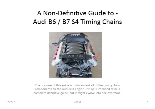
– Poor oil maintenance, excessive wear & tear (or bad luck) is the cause of +ming chain ra`le noises when one or more guides are unable to maintain perfect posi+oning of one or more +ming chains.
04/06/20
DraK 01
1
DISCLAIMER
• While a lot of effort has gone into compiling this document to provide accurate and independent informa+on that has been gathered from reputable sources - the author cannot be blamed, flamed or chas+sed on internet forums, social media (or down the local boozer) for geXng anything wrong here.
• Timing Chain Service
Indradrive 系列 故障代码

Error MessagesF9001 Error internal function call.F9002 Error internal RTOS function callF9003 WatchdogF9004 Hardware trapF8000 Fatal hardware errorF8010 Autom. commutation: Max. motion range when moving back F8011 Commutation offset could not be determinedF8012 Autom. commutation: Max. motion rangeF8013 Automatic commutation: Current too lowF8014 Automatic commutation: OvercurrentF8015 Automatic commutation: TimeoutF8016 Automatic commutation: Iteration without resultF8017 Automatic commutation: Incorrect commutation adjustment F8018 Device overtemperature shutdownF8022 Enc. 1: Enc. signals incorr. (can be cleared in ph. 2) F8023 Error mechanical link of encoder or motor connectionF8025 Overvoltage in power sectionF8027 Safe torque off while drive enabledF8028 Overcurrent in power sectionF8030 Safe stop 1 while drive enabledF8042 Encoder 2 error: Signal amplitude incorrectF8057 Device overload shutdownF8060 Overcurrent in power sectionF8064 Interruption of motor phaseF8067 Synchronization PWM-Timer wrongF8069 +/-15Volt DC errorF8070 +24Volt DC errorF8076 Error in error angle loopF8078 Speed loop error.F8079 Velocity limit value exceededF8091 Power section defectiveF8100 Error when initializing the parameter handlingF8102 Error when initializing power sectionF8118 Invalid power section/firmware combinationF8120 Invalid control section/firmware combinationF8122 Control section defectiveF8129 Incorrect optional module firmwareF8130 Firmware of option 2 of safety technology defectiveF8133 Error when checking interrupting circuitsF8134 SBS: Fatal errorF8135 SMD: Velocity exceededF8140 Fatal CCD error.F8201 Safety command for basic initialization incorrectF8203 Safety technology configuration parameter invalidF8813 Connection error mains chokeF8830 Power section errorF8838 Overcurrent external braking resistorF7010 Safely-limited increment exceededF7011 Safely-monitored position, exceeded in pos. DirectionF7012 Safely-monitored position, exceeded in neg. DirectionF7013 Safely-limited speed exceededF7020 Safe maximum speed exceededF7021 Safely-limited position exceededF7030 Position window Safe stop 2 exceededF7031 Incorrect direction of motionF7040 Validation error parameterized - effective thresholdF7041 Actual position value validation errorF7042 Validation error of safe operation modeF7043 Error of output stage interlockF7050 Time for stopping process exceeded8.3.15 F7051 Safely-monitored deceleration exceeded (159)8.4 Travel Range Errors (F6xxx) (161)8.4.1 Behavior in the Case of Travel Range Errors (161)8.4.2 F6010 PLC Runtime Error (162)8.4.3 F6024 Maximum braking time exceeded (163)8.4.4 F6028 Position limit value exceeded (overflow) (164)8.4.5 F6029 Positive position limit exceeded (164)8.4.6 F6030 Negative position limit exceeded (165)8.4.7 F6034 Emergency-Stop (166)8.4.8 F6042 Both travel range limit switches activated (167)8.4.9 F6043 Positive travel range limit switch activated (167)8.4.10 F6044 Negative travel range limit switch activated (168)8.4.11 F6140 CCD slave error (emergency halt) (169)8.5 Interface Errors (F4xxx) (169)8.5.1 Behavior in the Case of Interface Errors (169)8.5.2 F4001 Sync telegram failure (170)8.5.3 F4002 RTD telegram failure (171)8.5.4 F4003 Invalid communication phase shutdown (172)8.5.5 F4004 Error during phase progression (172)8.5.6 F4005 Error during phase regression (173)8.5.7 F4006 Phase switching without ready signal (173)8.5.8 F4009 Bus failure (173)8.5.9 F4012 Incorrect I/O length (175)8.5.10 F4016 PLC double real-time channel failure (176)8.5.11 F4017 S-III: Incorrect sequence during phase switch (176)8.5.12 F4034 Emergency-Stop (177)8.5.13 F4140 CCD communication error (178)8.6 Non-Fatal Safety Technology Errors (F3xxx) (178)8.6.1 Behavior in the Case of Non-Fatal Safety Technology Errors (178)8.6.2 F3111 Refer. missing when selecting safety related end pos (179)8.6.3 F3112 Safe reference missing (179)8.6.4 F3115 Brake check time interval exceeded (181)Troubleshooting Guide | Rexroth IndraDrive Electric Drivesand ControlsI Bosch Rexroth AG VII/XXIITable of ContentsPage8.6.5 F3116 Nominal load torque of holding system exceeded (182)8.6.6 F3117 Actual position values validation error (182)8.6.7 F3122 SBS: System error (183)8.6.8 F3123 SBS: Brake check missing (184)8.6.9 F3130 Error when checking input signals (185)8.6.10 F3131 Error when checking acknowledgment signal (185)8.6.11 F3132 Error when checking diagnostic output signal (186)8.6.12 F3133 Error when checking interrupting circuits (187)8.6.13 F3134 Dynamization time interval incorrect (188)8.6.14 F3135 Dynamization pulse width incorrect (189)8.6.15 F3140 Safety parameters validation error (192)8.6.16 F3141 Selection validation error (192)8.6.17 F3142 Activation time of enabling control exceeded (193)8.6.18 F3143 Safety command for clearing errors incorrect (194)8.6.19 F3144 Incorrect safety configuration (195)8.6.20 F3145 Error when unlocking the safety door (196)8.6.21 F3146 System error channel 2 (197)8.6.22 F3147 System error channel 1 (198)8.6.23 F3150 Safety command for system start incorrect (199)8.6.24 F3151 Safety command for system halt incorrect (200)8.6.25 F3152 Incorrect backup of safety technology data (201)8.6.26 F3160 Communication error of safe communication (202)8.7 Non-Fatal Errors (F2xxx) (202)8.7.1 Behavior in the Case of Non-Fatal Errors (202)8.7.2 F2002 Encoder assignment not allowed for synchronization (203)8.7.3 F2003 Motion step skipped (203)8.7.4 F2004 Error in MotionProfile (204)8.7.5 F2005 Cam table invalid (205)8.7.6 F2006 MMC was removed (206)8.7.7 F2007 Switching to non-initialized operation mode (206)8.7.8 F2008 RL The motor type has changed (207)8.7.9 F2009 PL Load parameter default values (208)8.7.10 F2010 Error when initializing digital I/O (-> S-0-0423) (209)8.7.11 F2011 PLC - Error no. 1 (210)8.7.12 F2012 PLC - Error no. 2 (210)8.7.13 F2013 PLC - Error no. 3 (211)8.7.14 F2014 PLC - Error no. 4 (211)8.7.15 F2018 Device overtemperature shutdown (211)8.7.16 F2019 Motor overtemperature shutdown (212)8.7.17 F2021 Motor temperature monitor defective (213)8.7.18 F2022 Device temperature monitor defective (214)8.7.19 F2025 Drive not ready for control (214)8.7.20 F2026 Undervoltage in power section (215)8.7.21 F2027 Excessive oscillation in DC bus (216)8.7.22 F2028 Excessive deviation (216)8.7.23 F2031 Encoder 1 error: Signal amplitude incorrect (217)VIII/XXII Bosch Rexroth AG | Electric Drivesand ControlsRexroth IndraDrive | Troubleshooting GuideTable of ContentsPage8.7.24 F2032 Validation error during commutation fine adjustment (217)8.7.25 F2033 External power supply X10 error (218)8.7.26 F2036 Excessive position feedback difference (219)8.7.27 F2037 Excessive position command difference (220)8.7.28 F2039 Maximum acceleration exceeded (220)8.7.29 F2040 Device overtemperature 2 shutdown (221)8.7.30 F2042 Encoder 2: Encoder signals incorrect (222)8.7.31 F2043 Measuring encoder: Encoder signals incorrect (222)8.7.32 F2044 External power supply X15 error (223)8.7.33 F2048 Low battery voltage (224)8.7.34 F2050 Overflow of target position preset memory (225)8.7.35 F2051 No sequential block in target position preset memory (225)8.7.36 F2053 Incr. encoder emulator: Pulse frequency too high (226)8.7.37 F2054 Incr. encoder emulator: Hardware error (226)8.7.38 F2055 External power supply dig. I/O error (227)8.7.39 F2057 Target position out of travel range (227)8.7.40 F2058 Internal overflow by positioning input (228)8.7.41 F2059 Incorrect command value direction when positioning (229)8.7.42 F2063 Internal overflow master axis generator (230)8.7.43 F2064 Incorrect cmd value direction master axis generator (230)8.7.44 F2067 Synchronization to master communication incorrect (231)8.7.45 F2068 Brake error (231)8.7.46 F2069 Error when releasing the motor holding brake (232)8.7.47 F2074 Actual pos. value 1 outside absolute encoder window (232)8.7.48 F2075 Actual pos. value 2 outside absolute encoder window (233)8.7.49 F2076 Actual pos. value 3 outside absolute encoder window (234)8.7.50 F2077 Current measurement trim wrong (235)8.7.51 F2086 Error supply module (236)8.7.52 F2087 Module group communication error (236)8.7.53 F2100 Incorrect access to command value memory (237)8.7.54 F2101 It was impossible to address MMC (237)8.7.55 F2102 It was impossible to address I2C memory (238)8.7.56 F2103 It was impossible to address EnDat memory (238)8.7.57 F2104 Commutation offset invalid (239)8.7.58 F2105 It was impossible to address Hiperface memory (239)8.7.59 F2110 Error in non-cyclical data communic. of power section (240)8.7.60 F2120 MMC: Defective or missing, replace (240)8.7.61 F2121 MMC: Incorrect data or file, create correctly (241)8.7.62 F2122 MMC: Incorrect IBF file, correct it (241)8.7.63 F2123 Retain data backup impossible (242)8.7.64 F2124 MMC: Saving too slowly, replace (243)8.7.65 F2130 Error comfort control panel (243)8.7.66 F2140 CCD slave error (243)8.7.67 F2150 MLD motion function block error (244)8.7.68 F2174 Loss of motor encoder reference (244)8.7.69 F2175 Loss of optional encoder reference (245)Troubleshooting Guide | Rexroth IndraDrive Electric Drivesand Controls| Bosch Rexroth AG IX/XXIITable of ContentsPage8.7.70 F2176 Loss of measuring encoder reference (246)8.7.71 F2177 Modulo limitation error of motor encoder (246)8.7.72 F2178 Modulo limitation error of optional encoder (247)8.7.73 F2179 Modulo limitation error of measuring encoder (247)8.7.74 F2190 Incorrect Ethernet configuration (248)8.7.75 F2260 Command current limit shutoff (249)8.7.76 F2270 Analog input 1 or 2, wire break (249)8.7.77 F2802 PLL is not synchronized (250)8.7.78 F2814 Undervoltage in mains (250)8.7.79 F2815 Overvoltage in mains (251)8.7.80 F2816 Softstart fault power supply unit (251)8.7.81 F2817 Overvoltage in power section (251)8.7.82 F2818 Phase failure (252)8.7.83 F2819 Mains failure (253)8.7.84 F2820 Braking resistor overload (253)8.7.85 F2821 Error in control of braking resistor (254)8.7.86 F2825 Switch-on threshold braking resistor too low (255)8.7.87 F2833 Ground fault in motor line (255)8.7.88 F2834 Contactor control error (256)8.7.89 F2835 Mains contactor wiring error (256)8.7.90 F2836 DC bus balancing monitor error (257)8.7.91 F2837 Contactor monitoring error (257)8.7.92 F2840 Error supply shutdown (257)8.7.93 F2860 Overcurrent in mains-side power section (258)8.7.94 F2890 Invalid device code (259)8.7.95 F2891 Incorrect interrupt timing (259)8.7.96 F2892 Hardware variant not supported (259)8.8 SERCOS Error Codes / Error Messages of Serial Communication (259)9 Warnings (Exxxx) (263)9.1 Fatal Warnings (E8xxx) (263)9.1.1 Behavior in the Case of Fatal Warnings (263)9.1.2 E8025 Overvoltage in power section (263)9.1.3 E8026 Undervoltage in power section (264)9.1.4 E8027 Safe torque off while drive enabled (265)9.1.5 E8028 Overcurrent in power section (265)9.1.6 E8029 Positive position limit exceeded (266)9.1.7 E8030 Negative position limit exceeded (267)9.1.8 E8034 Emergency-Stop (268)9.1.9 E8040 Torque/force actual value limit active (268)9.1.10 E8041 Current limit active (269)9.1.11 E8042 Both travel range limit switches activated (269)9.1.12 E8043 Positive travel range limit switch activated (270)9.1.13 E8044 Negative travel range limit switch activated (271)9.1.14 E8055 Motor overload, current limit active (271)9.1.15 E8057 Device overload, current limit active (272)X/XXII Bosch Rexroth AG | Electric Drivesand ControlsRexroth IndraDrive | Troubleshooting GuideTable of ContentsPage9.1.16 E8058 Drive system not ready for operation (273)9.1.17 E8260 Torque/force command value limit active (273)9.1.18 E8802 PLL is not synchronized (274)9.1.19 E8814 Undervoltage in mains (275)9.1.20 E8815 Overvoltage in mains (275)9.1.21 E8818 Phase failure (276)9.1.22 E8819 Mains failure (276)9.2 Warnings of Category E4xxx (277)9.2.1 E4001 Double MST failure shutdown (277)9.2.2 E4002 Double MDT failure shutdown (278)9.2.3 E4005 No command value input via master communication (279)9.2.4 E4007 SERCOS III: Consumer connection failed (280)9.2.5 E4008 Invalid addressing command value data container A (280)9.2.6 E4009 Invalid addressing actual value data container A (281)9.2.7 E4010 Slave not scanned or address 0 (281)9.2.8 E4012 Maximum number of CCD slaves exceeded (282)9.2.9 E4013 Incorrect CCD addressing (282)9.2.10 E4014 Incorrect phase switch of CCD slaves (283)9.3 Possible Warnings When Operating Safety Technology (E3xxx) (283)9.3.1 Behavior in Case a Safety Technology Warning Occurs (283)9.3.2 E3100 Error when checking input signals (284)9.3.3 E3101 Error when checking acknowledgment signal (284)9.3.4 E3102 Actual position values validation error (285)9.3.5 E3103 Dynamization failed (285)9.3.6 E3104 Safety parameters validation error (286)9.3.7 E3105 Validation error of safe operation mode (286)9.3.8 E3106 System error safety technology (287)9.3.9 E3107 Safe reference missing (287)9.3.10 E3108 Safely-monitored deceleration exceeded (288)9.3.11 E3110 Time interval of forced dynamization exceeded (289)9.3.12 E3115 Prewarning, end of brake check time interval (289)9.3.13 E3116 Nominal load torque of holding system reached (290)9.4 Non-Fatal Warnings (E2xxx) (290)9.4.1 Behavior in Case a Non-Fatal Warning Occurs (290)9.4.2 E2010 Position control with encoder 2 not possible (291)9.4.3 E2011 PLC - Warning no. 1 (291)9.4.4 E2012 PLC - Warning no. 2 (291)9.4.5 E2013 PLC - Warning no. 3 (292)9.4.6 E2014 PLC - Warning no. 4 (292)9.4.7 E2021 Motor temperature outside of measuring range (292)9.4.8 E2026 Undervoltage in power section (293)9.4.9 E2040 Device overtemperature 2 prewarning (294)9.4.10 E2047 Interpolation velocity = 0 (294)9.4.11 E2048 Interpolation acceleration = 0 (295)9.4.12 E2049 Positioning velocity >= limit value (296)9.4.13 E2050 Device overtemp. Prewarning (297)Troubleshooting Guide | Rexroth IndraDrive Electric Drivesand Controls| Bosch Rexroth AG XI/XXIITable of ContentsPage9.4.14 E2051 Motor overtemp. prewarning (298)9.4.15 E2053 Target position out of travel range (298)9.4.16 E2054 Not homed (300)9.4.17 E2055 Feedrate override S-0-0108 = 0 (300)9.4.18 E2056 Torque limit = 0 (301)9.4.19 E2058 Selected positioning block has not been programmed (302)9.4.20 E2059 Velocity command value limit active (302)9.4.21 E2061 Device overload prewarning (303)9.4.22 E2063 Velocity command value > limit value (304)9.4.23 E2064 Target position out of num. range (304)9.4.24 E2069 Holding brake torque too low (305)9.4.25 E2070 Acceleration limit active (306)9.4.26 E2074 Encoder 1: Encoder signals disturbed (306)9.4.27 E2075 Encoder 2: Encoder signals disturbed (307)9.4.28 E2076 Measuring encoder: Encoder signals disturbed (308)9.4.29 E2077 Absolute encoder monitoring, motor encoder (encoder alarm) (308)9.4.30 E2078 Absolute encoder monitoring, opt. encoder (encoder alarm) (309)9.4.31 E2079 Absolute enc. monitoring, measuring encoder (encoder alarm) (309)9.4.32 E2086 Prewarning supply module overload (310)9.4.33 E2092 Internal synchronization defective (310)9.4.34 E2100 Positioning velocity of master axis generator too high (311)9.4.35 E2101 Acceleration of master axis generator is zero (312)9.4.36 E2140 CCD error at node (312)9.4.37 E2270 Analog input 1 or 2, wire break (312)9.4.38 E2802 HW control of braking resistor (313)9.4.39 E2810 Drive system not ready for operation (314)9.4.40 E2814 Undervoltage in mains (314)9.4.41 E2816 Undervoltage in power section (314)9.4.42 E2818 Phase failure (315)9.4.43 E2819 Mains failure (315)9.4.44 E2820 Braking resistor overload prewarning (316)9.4.45 E2829 Not ready for power on (316)。
EATON 说明书
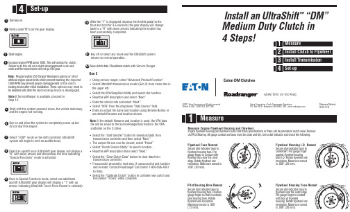
t f i h S a r t l U n a l l a t s n I ™” M D “Medium Duty Clutch in 4 Steps! :l a i r e t a M e c n e r e f e R LMT-1314C e clutch. h t k c o l n u l l i w s i h T . 0 0 5 1 e v o b a M P R e n i g n e e s a e r c nt code and n e m e g a g n e s i d h c t u l c a t e s l l i w s i h t od o te r u l i a . r a e go t n i o g t o n l l i w n o i s s i m s n a rt e h t d n a e d o c : e t o N other r o s n o i t po e c n a ts i se R r e p m a T S S V e l b a m m a r g o r P g the required n i hc a e r t n e ve r p h c i h w s t i m i l d e ep s e n i g n e l a i c i f i t r a t of the clutchn e m e g a g n e s idr ep o r p t n e v e r p y a m M P R 0 0 5 1e options may need to s e h T .n o it a l l a t s n i l a i t i n i r e t f a e c i v e d g n i k c o l locking device is disengaged. h- c t u l c e h t r e t f a l i t n u d e l b a s i d e b with Service Rangerh c t u l c e t a r b i l a c e R / a t a d h c t u l c e v a . n o y e k n r u n the gear display. o s i ” N “ d i l o s a y f i r e . e n i g n e t r a t SNote: If Ser v iceRanger is available, proceed to Step 12.“Special Functions” mode is activated.arrows indicating UltraShift Touch Point Resent is selected).After the “1” is displayed, depress the throttle pedal to the floor and hold for 3-5 seconds (the gear display will change back to a “0” with down arrows indicating the routine has been successfully completed.Key off or select any mode and the UltraShift systemreturns to normal operation. Gen 3• Using se rvice ranger, select “Advanced Product Function” • Select UltraShift transmission model (Gen 3) from menu tree in the upper left.• Select the V PA/SnapShot Utility and launch the function. • Read the APF description and select “Next” • Enter the vehicle info and select “Next.”• Select “V PA” from the dropdown “Data Source” field.• Enter an output file name and location using Browse Button or use default filename and location shown.Note: If the default filename and location is used, the VPA data file will be saved to the ServiceRangerData folder in the VPA subfolder on the C:\drive.• Select the “start transfer” button to download data from transmission controller and then select “Next.” • The output file can now be viewed, select “Finish” • Select “Clutch Se rvice Utility” to launch function. • Read the APF description then select “Next.”• Select the “Clear Clutch Data” button to clear data from transmission controller.• If successful proceed to next step, if unsuccessful exit function and re-enter. Contact Roadranger Call Center 1-800-826-4357 for help.• Select the “Calibrate Clutch” button to calibrate new cultch and then Select “Finish” when complete.le e h w y l F d n a g n i s u o H l e e h w y l F e n i g n E e r u s a e M e v o m e R . r a e w h c t u l c e r u t a m e r p e b l l i w e r e h t r o s n o i t a c if i c e p s e s e h t t e e m t s u m l e e h w y l f d n ag n i s u oh l e e h w y l f e ni g n E : g n i w o l l o f e h t k c e h c d n a r o t a c i d n i l a i d a e s U . y r d d n a n a e l c e b t s u m s e c a f r u s t c a t n o c e g u a g l l A . g n i r a e B t o l i P d l o t u o n u R e c a F l e e h w y l F o t e s a b r o t a c i d n i l a i d e r u c e S t u P . e c a f g n i s u o h l e e h w y l f h t i w t c a t n o c n i r e g n i f e g u a g r e t u o e h t r a e n e c a f l e e h w y l f e n o l e e h w y l f e t a t o R . e g d e s i t u o n u r m u m i x a M . n o i t u l o v e r .) m m 0 2 . ( " 8 0 0 . Runout e r o B g n i r a e B t o l i P o t e s a b r o t a c i d n i l a i d e r u c e S n o i t i s o P . e c a f g n i s u o h l e e h w y l f s t c a t n o c t i t a h t o s r e g n i f e g u a g e t a t o R . e r o b g n i r a e b t o l i p . n o i t u l o v e r e n o l e e h w y l f " 5 0 0 . s i t u o n u r m u m i x a M . ) m m 3 1 . (. D . I g n i s u o H l e e h w y l F o t e s a b ro t a c i d n i l a i d e r u c e S r e g n i f e g u a g t u P . t f a h s k n a r c g n i s u o h l e e h w y l f t s n i a g a e n o l e e h w y l f e t a t o R . D . I t o l i p t u o n u r m u m i x a M . n o i t u l o v e r .) m m 0 2 . ( " 8 0 0 . s i e c a F g n i s u o H l e e h w y l F o t e s a b r o t a c i d n i l a i d e r u c e S . e g d e r e t u o e h t r a e n l e e h w y l f t c a t n o c n i r e g n i f e g u a g t u P l e e h w y l f f o e c a f h t i w e n o l e e h w y l f e t a t o R . g n i s u o h t u o n u r m u m i x a M . n o i t u l o v e r .) m m 0 2 . ( " 8 0 0 . s i Eaton Corporation • Truck Components OperationsP .O. Box 4013 • Kalamazoo, MI 49003 USA ww ©2011 Eaton Corporation • All rights rese rved.Printed in USA. CLMT1320 0911 WPEaton DM ClutchesMore time on the roadCheck T ransmission For W ear Replace any worn components.the disc.Remove the guide studs and install the two remaining mounting bolts. Tighten the clutch mounting bolts in a crossing pattern as on any other clutch and torque to3/8"-16 UNC X 2.25" with lockwashers, minimum grade 5 covered by the Hex Cap Screw specification under ASME B18.2.1 1996. Torque to 30 - 35 lbs. ft.。
ELMO VP Receiver VPR-2 用户手册说明书
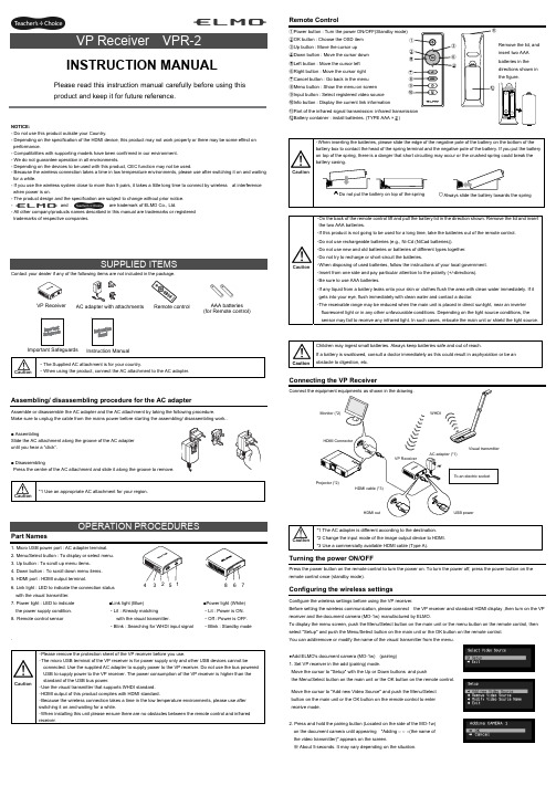
NOTICE:- Do not use this product outside your Country.- Depending on the specification of the HDMI device, this product may not work properly or there may be some effect on performance.- Compatibilities with supporting models have been confirmed in our environment. - We do not guarantee operation in all environments.- Depending on the devices to be used with this product, CEC function may not be used.- Because the wireless connection takes a time in low temperature environments, please use after switching it on and waiting for a while.- If you use the wireless system close to more than 5 pairs, it takes a little long time to connect by wireless at interference when power is on.- The product design and the specification are subject to change without prior notice. -and are trademark of ELMO Co., Ltd.- All other company/products names described in this manual are trademarks or registered trademarks of respective companies.Contact your dealer if any of the following items are not included in the package. Caution・The Supplied AC attachment is for your country.・When using the product, connect the AC attachment to the AC adapter.Assembling/ disassembling procedure for the AC adapterAssemble or disassemble the AC adapter and the AC attachment by taking the following procedure.Make sure to unplug the cable from the mains power before starting the assembling/ disassembling work..■ AssemblingSlide the AC attachment along the groove of the AC adapter until you hear a “click”.■ DisassemblingPress the centre of the AC attachment and slide it along the groove to remove. Caution *1 Use an appropriate AC attachment for your region.Part Names1. Micro USB power port : AC adapter terminal.2. Menu/Select button : To display or select menu.3. Up button : To scroll up menu items.4. Down button : To scroll down menu items.5. HDMI port : HDMI output terminal.6. Link light : LED to indicate the connection status with the visual transmitter.7. Power light : LED to indicate the power supply condition.8. Remote control sensor . Caution・Please remove the protection sheet of the VP receiver before you use.・The micro USB terminal of the VP receiver is for power supply only and other USB devices cannot beconnected. Use the supplied AC adapter to supply power to the VP receiver. Do not use the bus powered USB to supply power to the VP receiver. The power consumption of the VP receiver is higher than the standard of the USB bus power.・Use the visual transmitter that supports WHDI standard. ・HDMI output of this product complies with HDMI standard.・Because the wireless connection takes a time in the low temperature environments, please use after switching it on and waiting for a while.・When installing this unit please ensure there are no obstacles between the remote control and infrared receiver .Remote Control①Power button : Turn the power ON/OFF(Standby mode) ②OK button : Choose the OSD item ③Up button : Move the cursor up ④Down button : Move the cursor down ⑤Left button : Move the cursor left ⑥Right button : Move the cursor right ⑦Cancel button : Go back in the menu ⑧Menu button : Show the menu on screen ⑨Input button : Select registered video source ⑩Info button : Display the current link information⑪Part of the infrared signal transmission: infrared transmission⑫Battery container : install batteries. (TYPE AAA ×2)Caution・On the back of the remote control lift and pull the battery lid in the direction shown. Remove the lid and insert the two AAA batteries.・If this product is not going to be used for a long time, take the batteries out of the remote control. ・Do not use rechargeable batteries (e.g., Ni-Cd (NiCad batteries)). ・Do not use new and old batteries or batteries of different types together. ・Do not try to recharge or short-circuit the batteries.・When disposing of used batteries, follow the instructions of your local government. ・Insert from one side and pay particular attention to the polarity (+/-directions). ・Be sure to use AAA batteries.・If any liquid from a battery leaks onto your skin or clothes flush the area with clean water immediately. If it gets into your eye, flush immediately with clean water and contact a doctor.・The receivable range may be reduced when the main unit is placed in direct sunlight, near an inverter fluorescent light or in any other unfavourable conditions. Depending on the light source conditions, the sensor may fail to receive any infrared light. In such cases, relocate the main unit or shield the light source.CautionChildren may ingest small batteries. Always keep batteries safe and out of reach.If a battery is swallowed, consult a doctor immediately as this could result in asphyxiation or be an obstacle to digestion, etc.Connecting the VP ReceiverCaution *1 The AC adapter is different according to the destination. *2 Change the input mode of the image output device to HDMI. *3 Use a commercially available HDMI cable (Type A).Turning the power ON/OFFPress the power button on the remote control to turn the power on. To turn the power off, press the power button on the remote control once (standby mode).Configuring the wireless settingsConfigure the wireless settings before using the VP receiver.Before setting the wireless communication, please connect the VP receiver and standard HDMI display ,then turn on the VP receiver and the document camera (MO-1w) manufactured by ELMO.To display the menu screen, push the Menu/Select button on the main unit or the menu button on the remote control, then select "Setup" and push the Menu/Select button on the main unit or the OK button on the remote control. You can add/remove or modify the name of the visual transmitter from the menu.●Add ELMO's document camera (MO-1w) (pairing) 1. Set VP receiver in the add (pairing) mode.Move the cursor to "Setup" with the Up or Down buttons and push the Menu/Select button on the main unit or the OK button on the remote control.Move the cursor to "Add new Video Source" and push the Menu/Selectbutton on the main unit or the OK button on the remote control to enter receive mode.2. Press and hold the pairing button (Located on the side of the MO-1w) on the document camera until appearing "Adding ○ ○ ○(the name of the video transmitter)" appears on the screen.※ About 5 seconds. It may vary depending on the situation.CautionPlease read this instruction manual carefully before using this product and keep it for future reference.INSTRUCTION MANUALInstruction ManualVP Receiver3 4 5 6 7■Link light (Blue) ・Lit : Already matchingwith the visual transmitter.・Blink : Searching for WHDI input signal■Power light (White) ・Lit : Power is ON. ・Off : Power is OFF. ・Blink : Standby modeAC adapter with attachments AAA batteries (for Remote control)Important Safeguards ⑪Remove the lid, and insert two AAA batteries in the directions shown in the figure. 83. Move the cursor to "OK" on the screen and push the Menu/Select button on the main unit or the OK button on the remote control.Pairing will start. The image of the documemt camera displays automatically when pairing finishes.If the pairing stops please turn the power of VP receiver power off and the document camera, and restart pairing.4. If you wish to register more than 1 document camera, repeat form step 1. (Up to eight document cameras can be paired). Caution ・For details about the operation of the Visual transmitter, refer to the instruction manual of the respective Visual transmitter.■Remove the visual transmitter1. Select “Setup”. Then press the Menu/Select button on the main unit or the OK button on the remote control.2. Select “Remove Video Source” from the menu. Then press the Menu/Select button of the main unit or the OK button of the remote control.3. Select the name of Visual transmitter to remove. Then press the Menu/Select button of the main unit or the OK button of the remote control.4. Select “OK” and press the Menu/Select button or the OK button of the remote control.5. The confirmation of "Removing ○ ○ ○(Name of the transmitter) " appears, then select OK and press the Menu/Select button on the main unit or the OK button on remote control.■Modify the name of the visual transmitter1. Select “Setup”. Then press the Menu/Select button.2. Select “Modify Video Source Name” from the menu. Then press the Menu/Select button on the main unit or the OK button on the remote control.3. Select the registered visual transmitter. Then press the Menu/Select button on the main unit or the OK button on the remote control.4. (Using the main unit) Use the Up or Down buttons to move the cursor left and right to the character you want to change. Press the Menu/Select button and cursor will change colour to confirm selection. Now usethe up and down buttons to move to the new character you want to replace the old one with and press the Menu/Select button to confirm.(Using the remote control) This is the same procedure as the main unit, but use the remote control left or right button to move the cursor, the up or down buttons to change the character and press the OK button to confirm.5. Once completed press and hold the Menu/Select button on the main unit or press the OK button on the remote control. Then select “Save” and press the Menu/Select button on the main unit or the OK button on the remote control.Selecting the Video SourceDisplay the menu by pressing the Menu/Select button.A list of registered visual transmitters appears in the menu. Select the desired visual transmitter. Press the Menu/Select button to output the image of the selected visual Transmitter.In addition, by pressing the Input button on the remote control you can output video by selecting the video transmitter registration.When the message of “Please remove and register this ○○○ again” is shown while linking with the transmitter, please remove and add the transmitter again.Info MenuPush the Info button on the remote control, to display the current link status. The registered name of the video transmitter and signal strength of the video is displayed on the transmitter.How to wall mount this unitIf you install on a wall as shown below, please install with standard screws (not supplied).If trouble occurs or you have any queries, first check this section.If the problem persists, check your warranty and contact the dealer where you purchased the product.The AC adapter is disconnected. Check the connection between the AC adapter and the wall outlet.Is the visual transmitter registered? Add the visual transmitter.Equipment which uses the same frequency may cause radio interference. Check the surrounding radio frequency environment.The VP Receiver does not work.The AC adapter is disconnected from the VP Receiver.Check the connection between the AC adapter and the VP Receiver. HDMI cable is not connected properly.Firmly insert HDMI cable into the connector. The cable is damaged.Do not use a damaged cable. (Replace the cable)The input signal is out of the display range of the visual transmitter. Check the resolution.No image is displayed. orThe image is distorted.Equipment which uses the same frequency may cause radio interference.Check the surrounding radio frequency environment.HDMI cable is not connected properly.Firmly insert HDMI cable into the connector. The cable is damaged.Do not use a damaged cable.No audio from the visual transmitter is input. No sound is output when there is no audio input.No sound is output.The volume of the visual transmitter or the image output device is set to minimum. Turn up the volume.Caution・When error messages appear, follow the instructions to fix the error. ・If the problem persists, the product may be defective. Contact the dealer where you purchased the product for repair.PRODUCT SPECIFICATIONSOperating Temperature 0℃ - 40℃ (32°F – 104°F) Wireless Band Used 5190MHz - 5670MHz Communication DistanceApprox. 10m (32.8feet)(differs depending on the usage conditions) Power Supply AC adapterInput: 100V-240V, 50/60Hz(0.3A)Output: 5V, 2AStandards HDMI / WHDI standard compliance, including HDCP Transmitter registration 8 setsImage output:VGA (640x480)60Hz/75Hz, SVGA (800x600)60Hz/75Hz, XGA (1024x768) 60Hz/75Hz, WXGA (1280x768) 60Hz, WXGA (1280x800) 60Hz, SXGA (1280x1024) 60Hz/75Hz1152x864 (60Hz), 1280x960(60Hz) 480p, 576p, 720p, 1080i, 1080p HDMI OUT (Type A)Audio output: 192 kHz x 24 bitPower Consumption (Current) 7W( 5V / 1.4A) without AC adapterExternal DimensionsL83 x W80 x H31 (mm)L3 1/4” x W3 1/8” x H1 1/4”Weight 110g (0.24lb)6-14, Meizen-cho, Mizuho-ku, Nagoya, 467-8567, JapanELMO Europe SASHeadquartersImmeuble Elysées La Défense, 7C Place du Dôme, 92056 Paris La Défense, FRANCETel: +33 (0) 1 73 02 67 06 Fax: +33 (0) 1 73 02 67 10E-mail: *********************: /German BranchHansaallee 201, Haus 140549 Düsseldorf, GermanyTel: +49 (0)211 544756 40 Fax: +49 (0)211 544756 60E-mail: ******************** Web: http://www.elmo-germany.de/VPR-2(E2)_M R0-XexCAMERA 1CAMERA 2Pairing ButtonThe side panel of the MO-1wSelection order of the transmitterVP ReceiverPushSignal strengthName of the video transmitter Wall Mount screws are not included. Please use the screws as shown below. The screw head should be about 5mm from wall.When mounted to wall, the remote control operation range is 30 ° left and right , 30 ° to the front wall as shown in the figure.Please attach the screws to the wall. When attached to the wall of the hollow wall material such as gypsum board, please use the plug anchor corresponding to each of the wall material.The distance between screw and screw is 50mm.Then hook the screw hole on the unit.。
潍柴汽车产品说明书
I
INDEX
v w
Main Menu
Index
Changing Oil How to......................................... 147 When to...................................Байду номын сангаас... 135
Charging System Indicator .... 46, 186 Checklist, Before Driving............. 123 Child Safety ...................................... 29
Booster Seats ............................... 38 Child Seats.................................... 34 Important Safety Reminders ...... 32 Larger Children ........................... 37 Risk with Airbags ........................ 30 Small Children.............................. 33 Child Seats........................................ 34 Cleaning Seat Belts........................ 160 Clock.................................................. 54 Clutch Fluid.................................... 154 CO in the Exhaust ......................... 207 Cold Weather, Starting in ............. 124 Compact Spare Tire....................... 174 Consumer Informationˎ................ 212 Controls, Instruments and.............. 43 Convertible Top ............................... 70 Convertible Top Cover................ 72 Lowering the Convertible Top... 70 Maintenance................................. 74 Raising the Convertible Top ...... 73
2007年福特自由式快速参考指南说明书
FREESTYLE2007QUICK REFERENCE GUIDE2007FREESTYLE *7F9J-19G217-AA*7F9J-19G217-AAFEBRUARY 2006FIRST PRINTINGQUICK REFERENCE GUIDE624848121LOCATION OF SPARE TIRE AND TOOLSYour vehicle is equipped with a temporary spare tire,which is smaller than a regular tire,and designed for emergency use only.The jack,spare tire,jack handle,and lug nut wrench are under the carpeted floor panel in the rear of the vehicle.If the 3rd row seat is stowed in the floor,you will need to unstow it to access the spare tire and jack.FUSESIf your electrical components aren't working properly,a fuse may have blown.Please consult your Owner's Guide.FUEL PUMP SHUT-OFF SWITCHThis device stops the electric fuel pump from sending fuel to the engine when your vehicle has had a substantial jolt.After an accident,if the engine cranks but does not start,this switch may have been activated.The fuel pump shut-off switch is located in the front passenger footwell area in the right upper corner.For switch reset instructions,please consult your Owner's Guide.UNLEADED FUEL RECOMMENDATIONSFor optimum performance,use “Regular”unleaded fuel with a pump (R+M)/2octane rating of at least 87.We do not recommend the use of gasolines labeled “Regular”with octane ratings of 86or lower that are sold in high altitude areas.TIRE PRESSURESafe operation of your Freestyle requires that your tires be properly inflated.The Ford recommended inflation pressure is found on the Tire Label or the Certification Label located near the front door latch on the driver's side.At least once a month and before long trips,inspect each tire and check the air pressure with a digital or dial-type tire gauge.Don't forget the spare.Air pressure should be checked when the tires are cold.Inflate all tires to the inflation pressure recommended by Ford Motor Company.ROADSIDE ASSISTANCEIn addition to your New Vehicle Limited Warranty,Ford provides new vehicle owners with a complimentary roadside assistance program.This service is available 24hours a day,seven days a week,for three years or 36,000miles (60,000km).It covers changing a flat tire,jump starts,limited fuel delivery,lock-out assistance,winch out,and towing of your vehicle.United States (800)241-3673Canada (800)665-2006UNDERSTANDING THE CVTThe Continuously Variable Transaxle (CVT)is a fully automatic transmission that electronically monitors vehicle system inputs/outputs and driver demands to select the desired drive ratio.Unlike traditional automatic transmissions,the CVT continually adjusts the optimum overall drive ratio between engine and drive wheels for all operating conditions.As traditional automatic transmissions shift up or down in gears,the shifting in gear ratios is noticeable by increasing and decreasing engine RPM,which causes a slight energy loss as the gears change.The gear changes can be felt by the driver.With the CVT,there is no energy transfer loss from shifting because there is no gear shifting up or down.Accelerating up to vehicle operating speed is smooth and continuous,uninterrupted by gear shifting.The same holds true for coasting down to idle:smooth and continuous.Unlike traditional automatic transmissions,the CVT offers more responsive performance and increased fuel economy.The use of fluids other than the recommended fluid could seriously damage internal transmission components.Please consult your Owner’s Guide.REAR WINDOW BUFFETINGWhen one or both of your rear windows are fully open,you may experience a wind throb or buffeting noise.This is common among all vehicles and can be eliminated simply by lowering a front window two to three inches.POWER SIDE MIRRORSRotate the control clockwise to adjust theright mirrorand counterclockwise toadjust the leftmirror.Move the controlin thedirection you wish totilt themirror.Rotate thecontrol to thecenter position to lock the mirrors in place.REMOTE ENTRY SYSTEMYour vehicle is equipped with a remote entry system which allows you to lock or unlock the doors.It also allows you to activate a panic alarm with thekey in the 1(LOCK)or 2(ACC)position.The remote entry system can also control the memory seat/power mirrors/adjustable pedals feature (if equipped).Please consult your Owner's Guide.KEYLESS ENTRY KEYPADThe keyless entry keypad can be used to lock or unlock the doors without using a key.It can also control the memory seat,power mirrors,and adjustable pedals (if equipped).Please consult your Owner’s Guide.MEMORY FEATURE(IF EQUIPPED)This feature will allow you to set two positions for the driver's seat,power mirrors,and adjustable pedals (if equipped).Please consult your Owner's Guide.ADJUSTABLE PEDALS(IF EQUIPPED)The accelerator and brake pedal should only be adjusted when the vehicle is stopped and the gearshift is in the P (Park)position.Press thetop of the control to adjust thepedals away from you,or press the bottom of the control to adjust the pedals toward you.HOMELINK ®(IF EQUIPPED)The HomeLink Wireless Control System on the driver's visor provides a convenient way to replace up to three handheld transmitters with a single device.This feature willoperate most garage doors,entry gate operators,security systems,and home or office lighting.For programming,please consult your Owner's Guide.HEATED SEATS(IF EQUIPPED)Press the heated seat button to cycle through available settings of high heat (2lights),low heat (1light),and off (no lights).REVERSE SENSING SYSTEM(IF EQUIPPED)The Reverse Sensing System (RSS)sounds a tone to warn the driver of obstacles near the rear bumper when R (Reverse)is selected and the vehicle is moving at speeds less than 3mph (5km/h).The system is not effective at speeds above 3mph (5km/h)and may not detect certain angular or moving objects.CLIMATE CONTROLDual Zone Automatic Temperature Control (IF EQUIPPED)Driver and Passenger Side TemperatureSet desired cabin temperature with the blue and red buttons.Press to increase or decrease the temperature on the driver or passenger side of the cabin.Dual Control (IF EQUIPPED)Press DUAL to engage/disengage separate passenger side temperature control.For controls without a DUAL button,press and hold AUTO to engage/disengage separate passenger side temperature control.Automatic OperationSet desired cabin temperature.Then press AUTO for full automatic operation.The system will automatically adjust airflow temperature,front fan speed,airflow direction,A/C,and recirculated air based on the selected temperature to heat or cool the vehicle to the desired temperature as soon as possible.Defogging/DemistingPress Defrost to distribute outside air through the windshield defroster vents and demister vents.To reduce humidity build-up in the vehicle,do not drive with the climate control turned off.Also,do not drive with recirculated air selected unless the A/C is operating.Air Flow Direction Control (IF EQUIPPED)Press repeatedly to select desired airflow direction.Heated Seats (IF EQUIPPED)Press to cycle through available settings of high heat (2lights),low heat (1light),and off (no lights).Rear (IF EQUIPPED)Press to give rear passenger control of the auxiliary climate system.Press again to turn system off.Rear Temperature Control (IF EQUIPPED)Press to increase or decrease temperature to the rear of the vehicle.Rear Fan Speed Control (IF EQUIPPED)Press to increase or decrease the rear fan speed.18222120191416131517On/Off/Volume ControlPush to turn ON or OFF .Turn to increase or decrease volume.If the volume is set above a certain level and the ignition is turned off,the volume will come back on at a “nominal”level when the ignition switch is turned back on.Tune/Disc SelectorPress to go up or down the radio frequency band or to select a desired disc.Also use in MENU mode to select various settings.Bass/TreblePress MENU until Bass/Treble settings are displayed.Adjust using the SEEK control.Balance/FadePress MENU until Balance is displayed.Press to adjust the audio between the left and right speakers using the SEEK control.Press MENU again to display Fade.Press to adjust audio between the front and rear speakers using the SEEK control.MP3Track/Folder ModeIn Track mode,pressing SEEK will scroll through all tracks on the disc.In Folder mode,pressing SEEK will scroll only through tracks within a selected folder.CDPress to enter CD mode.If a CD is already loaded into the system,the CD will begin playing where it last ended.LOADPress LOAD to begin the CD load sequence.When the display prompts to select a slot,use the desired slot to load the CD.Press and hold LOAD to autoload up to 6CDs,one at a time,when the display prompts to load a CD.AM/FMPress to select AM or FM frequency bands.Setting Memory Presets To set a station:Select AM/FM frequency band,tune to a station,then press and hold a preset button until the sound returns.SCAN controlPress for a brief sampling of radio stations or CD tracks.Press again to stop.SEEK controlPress to access the next/previous strong station or track.Setting the ClockPress MENU until SELECT HOUR or SELECT MINS is e the up/down arrows and SEEK control to adjust the hours/minutes.Dual Play/Single PlayIf the vehicle has a DVD system,simultaneously press preset buttons 2and 4to switch between Dual Play and Single Play.Please consult your Owner's Guide for DVD system operation.117121098654321SEATINGFront Passenger Fold Flat Seat Back The front passenger seat back can be folded down to a horizontal position to allow room for a long load.Ensure that the seat is in the rearmost position and the headrestraint is fully down,prior to pulling the strap located on the back of the seat back.Adjusting 2nd Row Bucket and Bench Seats Lift the side handle to adjust the seat ing the same control will fold the seat back flat.Lifting the control (if equipped)located underneath the seat cushion will adjust the seat forward or backward.Accessing the 3rd Row Seats Ensure that the 2nd row seat adjustable head restraints (if equipped)are in the full down position and no objects such as books,purses,or briefcases are onthe floor in front of the 2nd row seats before folding them down.Place the front row seat in a forward position to allow the 2nd row seat to be fully ”tumbled.”Lift the handle once to fold the seat back flat.Lift the same handle a second time to “tumble”the seat forward to allow access to the 3rd row seat.Stowing the 3rd Row Bench or Split Bench Seat in TubMove the adjustable head restraint (if equipped)fully down.Ensure that the stowage tub is clear of objects prior to cycling.From the rear of the vehicle,foldthe seat back by pulling and holding the number 1strap while pushing the seat back forward.Release the strap after the seat back starts rotating forward.Release the cushion latches by pulling the number 2strap while pulling on the long strap located on the seat back,to rotate the seat all the way into the tub in the floor.ESSENTIALINFORMATION ADDITIONALFEATURESAUDIO SYSTEMPremium/Audiophile In-Dash 6-CD/MP3Sound System (IF EQUIPPED)1234567891011121719191820212213141615Max A/C OperationAutomatic Operation:Press AUTO for full automatic operation.Do not override A/C or recirculated air.Set the temperature to 60°F (16°C).Override Operation:Select air distribution.Select A/C and recirculated e recirculated air with A/C to provide colder airflow.Set temperature to 60°F (16°C).Set to highest front fan speed initially,then adjust to maintain comfort.Manual Override OperationSet desired cabin temperature.Adjust any of the following for personal comfort preferences:front fan speed,airflow direction,A/C,and recirculated air.Front fan speed,A/C,and recirculated air overrides will not turn off the AUTO indicator light.Airflow direction overrides will turn off the AUTO indicator light.ONE |HEADLAMP CONTROLTurning the headlamp control clockwise to the first position turns on the parkinglamps,instrument panellamps,license platelamps,and thetail lamps.Continuingto turn theheadlamp control tothe second positionturns on theheadlamps.To use theautolamp light-sensitive,automatic on-off control for the headlamps,turn the headlamp control counterclockwise.To turn autolamps off,turn the control clockwise to the O (OFF)position.To activate the high beams,simply pull the turn signal lever towards you to the second detent.Pull the lever towards you again to deactivate e the same lever to activate the “Flash to Pass”feature.Pull the lever towards you to the first detent to activate and release it to deactivate.TWO |FOGLAMP CONTROL (IF EQUIPPED)With the ignition on,the foglamps can be turned on when the headlamp control is in the parking lamp,headlamp,or autolamp position,and the high beams are not on.Simply pull the headlamp control towards you to turn on the foglamps.The foglamp indicator light will illuminate.The foglamps will not operate when the high beams are activated.THREE |PANEL DIMMERUse this control to adjust the brightness of the instrument panel and all applicable switches in the vehicle during headlamp and parking lamp operation.Move the control to the full upright position,past the detent,to turn on the interior lamps.FOUR |HOOD RELEASETo open the hood,pull the hood release handle under the bottom of the instrument panel,near the steering column.Go to the front of the vehicle and release the auxiliary latch located under the front center of the e the prop rod to support the raised hood.FIVE |SPEED CONTROLFor your speed control to work,you must press and release the ON button.Pressing and releasing the OFF button,disengages the system and turns it off.To set a desired speed,accelerate to the desiredspeed,press and release the SET+button,then take your foot off the accelerator pedal.You can increase speed using speed control by pressing and releasing the SET+button until you reach the desired speed,increasing speed by 1mph (1.6km/h)with each tap.You can decrease speed in the same way using the SET-button.Pressing the RSM(resume)button will automatically return the vehicle to the previously set speed.The RSM control will not work if the vehicle speed is below 30mph (48km/h)or if the OFF button was pressed.To disengage the speed control,press the OFF or CNCL button or press the brake.SIX |TIL T STEERING COLUMNTo adjust the steering wheel,push the adjustment lever down to unlock the steering column.While the lever is down,tilt the steering column to your desired position.While holding the steering column in place,pull the lever up to its original position to lock the steering column.Do not adjust while driving.SEVEN |STEERING WHEEL AUDIO CONTROLS (IF EQUIPPED)These controls allow you to adjust the radio and CD features from the steering wheel.Press MEDIA to select AM,FM1,FM2or CD.Press SEEK to access the next/previous strong station or track on a CD.Press VOL+/-to adjust volume and MUTE to mute the volume.EIGHT |WINDSHIELD WIPER /WASHERThe multifunction lever controls the windshield wiper modes,speeds,and the windshield washer.For intermittent operation,move the control up one position.You can then adjust the rotary control to the desired interval speed.For normal or low wiper speed,move the control up two positions from OFF.For high speed operation,move the control up three positions from OFF.For windshield washer control,pull the end of the lever toward you.Abrief pull causes a single swipe of the wipers without washer fluid.With a quick pull and hold,the wipers will swipe three times with washer fluid.A long pull and hold will activate the wipers and washer fluid for up to ten seconds.NINE |TRACTION CONTROL ™(IF EQUIPPED)This system helps you maintain the stability and steerability of your vehicle on slippery road surfaces such as snow,ice,or gravel.The system works closely with many of the elements already present in the Anti-lock Braking System.The system defaults to ON.However,should you become stuck,try switching the Traction Control™off.ONE TWO THREE FOUR FIVE SIX SEVEN EIGHT NINETEN |THROTTLE CONTROL /TRANSMISSION LAMPThe throttle control /transmission lamp illuminates when a powertrain fault or an AWD fault (if equipped)has been detected.Contact your dealer as soon as possible.ELEVEN |ENGINE COOLANT LAMPThe engine coolant lamp Illuminates when the engine coolant is low.Stop the vehicle as soon as safely possible and let the engine cool.TWEL VE |ABS WARNING LAMPIn an emergency,apply continuous force to the brake pedal.Do not pump the brakes.Any pulsation or mechanical noise you may feel or hear is normal.If the lamp stays on or continues to flash,have your vehicle serviced.Normal braking is still functional unless the brake warning lamp is also illuminated.THIRTEEN |MESSAGE CENTER (IF EQUIPPED)With the ignition in the RUN position,the message center displays important vehicle information by constantly monitoring vehicle systems.You may select display features on the message center for a display of status,preceded by a brief indicator chime.The system will also notify you of potential vehicle problems with a display of system warnings.For more detailed information,please consult your Owner's Guide.FOURTEEN |CHECK ENGINE LAMPThe check engine indicator lamp illuminates when the ignition is first turned to the RUN position to check the bulb.If the lamp stays on or blinks,the On Board Diagnostics System has detected a malfunction.Drive in a moderate fashion (avoid heavy acceleration or deceleration)and have your vehicle serviced immediately.As the owner of this very capable,very versatile and most refined new Ford Freestyle,you really are…ready to go.And wherever you're going,you'll get there with confidence and style.Pack it for work,pack it for play...your new Ford Freestyle is ready to take you…well…just about anywhere.From tight city streets to snow-covered country roads,your adventures are about to begin.So,what are you waiting for?Let's go.This Quick Reference Guide was designed to help you quickly get to know your new Freestyle and its features.For the most detailed information,please consult your Owner's Guide.So,let's get started.The sooner you know more about your new Freestyle…the sooner you can get packing.ADVENTURES FREESTYLE2007QUICK REFERENCE GUIDEINSTRUMENT PANEL ANDINTERIORFEATURES。
Thermo King 冰箱产品说明书
Simple to SelectHigh Speed Lockout FeatureSimple to operateSmartPower™ Electric Standby (OPTION)For more information or tutorialsessions, please contact yourThermo King Service ManagerThe High Speed Lockout feature istypically used in noise sensitive areas toreduce diesel engine noise. This featuredoes not have any effect when operatingin electric standby mode.1. Press the High Speed Lockout key.• Amber LED will illuminate indicatingthe unit is in High Speed Lockout.2. Pressing the High Speed Lockout keyagain will turn the feature off.1. Connect the proper voltage powersupply to the unit’s power receptacle.2. Press the ON key to turn the unit on.• The preheat buzzer will sound for20 seconds before the electric motorstarts.TK 61004-8-PC-EN (Rev. 0, 01/13) ©Thermo King Corporationautomatically Switching from electric to dieselIf the electric to diesel auto Switch enabled feature is set to YES, the unit willautomatically switch from Electric Standby Mode to Diesel Mode when standby poweris removed or fails.automatically Switching from diesel to electricIf the diesel to electric auto Switch enabled feature is set to YES, the unit willautomatically switch from Diesel to Electric Standby Mode when standby power isdetected or connected .display will show all zeros to indicateno alarms codes exist.• All alarms must be viewed before any alarms can be cleared.• If an alarm will not clear, it may still exist. If the alarm is not corrected, it will notclear or may immediately be set again.• Some alarms cannot be cleared using the HMI.See operator’s manual for more information regarding alarm codes.1. Press the ON key to turn the unit on.• Dashes will appear in both the upperand lower portions of the display asit powers up.• The running time hour meters arethen displayed briefly.• The standard display will appearshowing the Box Temperature andthe Setpoint Temperature.• The diesel engine will preheat andstart as required when the unit isturned on. On SmartPower equippedunits, the electric standby motorwill start if the unit is connected tostandby power.2. Press the OFF key to turn the unit off.• The unit will immediately shut offand the display will go blank.1. Press the CYCLE-SENTRY/Continuouskey to change from CYCLE- SENTRYto Continuous mode.• Amber LED indicates the unit isoperating in CYCLE-SENTRY mode.• No LED illuminated indicates theunit is operating in Continuousmode.1. Press the DEFROST key to initiate amanual defrost.• Amber LED next to the DEFROSTkey indicates the unit is in defrost.NOTE: The defrost cycle terminates automatically when the evaporator coil reachesa predetermined temperature or when the defrost timer expires. Defrost can also beterminated by turning the unit off and back on.fUll pretrip teStNOTE: Full Pretrip must be done withthe unit not running.1. Press the UP or DOWN Arrow keysuntil the desired setpoint is shown.2. Press the ENTER key to confirm thenew setpoint.Simple to SetSetpoint Temperature1. Turn the unit on, clear all alarm codes and turn the unit off.2. Turn the unit on again and wait for the unit running time hourmeters to bedisplayed. Once the hourmeters are displayed, press and hold the PRETRIP key for5 seconds.• Flashing LED indicates that the Pretrip is being initialized.• Steady amber LED indicates the Pretrip is in process.• Full Pretrip Test typically lasts 20 to 30 minutes.• The amber LED will turn off when the Pretrip Test is complete or if a ShutdownAlarm occurs.enGine rUnninG pretrip teStNOTE: Engine Running Pretrip Test must be done with the unit running.1. Turn the unit on, clear all alarm codes and allow the unit to start.2. With the unit running, press and hold the PRETRIP key for 5 seconds.• Flashing LED indicates that the Pretrip is being initialized.• Steady amber LED indicates the Pretrip is in process.• Full Pretrip Test typically lasts 20 to 25 minutes.• The amber LED will turn off when the Pretrip Test is complete or if a ShutdownAlarm occurs.To stop a Pretrip Test at any time, press the OFF key to turn the unit off. This willgenerate an Alarm Code 28 Pretrip Abort.pretrip teSt reSUltSPass Pretrip Test• If the unit passes the Pretrip Test, the amber Pretrip Test LED will turn off at thecompletion of the test and the unit will continue to run as required.Fail Pretrip Test with Check Alarms• If the unit fails the Pretrip Test with Check Alarms, the Alarm Icon will appear whenthe alarm condition occurs. The Pretrip Test will continue to run unless a ShutdownAlarm occurs.See operator’s manual for more information regarding alarm codes.。
Cat 320 挖掘机说明书
Cat® 320Hydraulic ExcavatorThe Cat® 320 excavator brings premium performance with simple-to-use technologies like Cat GRADE with 2D, Grade Assist, and Payload – all standard equipment from the factory to boost your operator efficiencies up to 45 percent. Combine these features with a new cab, longer maintenance intervals that lower your maintenance costs up to 15 percent, and a power system that reduces fuel consumption by up to 25 percent and you have a low-cost-per-unit-of-production excavator that’s perfect for medium- to heavy-duty applications. Not all features available in all regions. Consult your Cat dealer for specific configurations available in your region.High Performance with Lower Fuel Consumption• Use up to 2 5 percent less fuel than the Cat 3 20F excavator.• Increase operating ef fi ciency up to 4 5 percent with standardCat Connect technologies that lower operator fatigue and youroperating costs, including fuel consumption and daily maintenance.• The C 4.4 ACER T™ engine can run on biodiesel up to B2 0 and meetsU.S. EPA Tier 4 Final and EU Stage IV emission standards with anaf t er t reatment system that requires no maintenance or downtime.• The advanced hydraulic system provides the optimum balanceof power and ef fi ciency while giving you the control you needfor precise digging requirements.• Match the excavator to the job with power modes; let Smar tmode automatically match engine and hydraulic power to diggingconditions.• Auxiliar y hydraulic options give you the versatilit y to use a widerange of Cat at t achments.• Available Smar t Boom™ lets the boom freely travel up and downwithout using any pump flow so operators can focus on stick andbucket work. The benefits are reduced operator stress and reducedfuel consumption.• Don’t let the temperature stop you from working. The excavatorhas a standard ambient temperature capabilit y of 4 6° C (115° F) andoptional high-ambient capabilit y of 5 2° C (12 5° F ). S t andard coldstar t capabilit y is – 32° C (–2 5° F ).Boost Efficiency and Boost Productivitywith Integrated Cat Connect Technologies• Boos t productivit y up to 4 5 percent versus traditional gradingwith s t andard Cat GR A DE with 2D system – includes indicate-onlyand laser capabilit y.– Dig with guidance to depth, slope, and horizontal distanceto grade.– The 2D system is upgradable to Cat GR A DE with Advanced 2Dor Cat GR A D E with 3D.• S t andard Grade Assist:– S t ay on grade – simply and ef f or t lessly – with single-lever digging.– Set your desired bucket angle and let Bucket Assis t automaticallymaintain the angle in sloping, leveling, fine grading, and trenchingapplications for easy, accurate, and fast jobs.– Keep the tracks on ground in lif t ing and hard digging withBoom Assist .– Automatically s t op excavator swing at operator-defined setpoints in truck loading and trenching applications with SwingAssist , which will help you use less ef f or t and consume less fuel.• S t andard Cat PAYLOAD on-board weighing system:– Achieve precise load targets and increase loading ef fi ciencywith on-the-go weighing and real-time es t imates of your payloadwithout swinging.– Track your daily productivit y such as truck target weights andload/cycle counts.– Calibration can be per f ormed in a mat t er of minutes.– Combine Payload with VisionL i nk® and remotely manage yourproduction targets.• Upgrade to optional Cat GR A DE with Advanced 2D:– Create and edit grade designs with ease on a second high-resolution 2 54 mm (10 in) touchscreen monitor.• Upgrade to optional Cat GR A DE with 3D:– Create and edit designs with ease and see the front linkage’sfull range of motion on a second high-resolution 25 4 mm (10 in)touchscreen monitor.– Know the excavator ’s exact position relative to GPS andGLONASS systems.– The machine automatically compensates for excavator pitchand roll caused by sloping ground conditions.• S t andard Product Link™ provides location, machine hours, fuelusage, productivit y, idle time, diagnostic codes, and other machinedata on demand through V i sionLink online inter f ace, helping youimprove job site ef fi ciency with lower operating cos t s.Cat® 320 Hydraulic ExcavatorWork in Comfort in the All-New Cab• Choose bet w een Comfor t and Deluxe cabs – both with automatic climate control.• Sit in wide seats that adjust for all size operators; s t ay warm with the Deluxe heated seat.• Enjoy wide spacing bet w een consoles for a more comfor t able environment .• Get in and out of the cab easier using the tip-up lef t console (Deluxe cab only).• Advanced viscous mounts reduce cab vibration up to 5 0 percent over previous excavator models.• Control the excavator comfor t ably with easy-to-reach controlsall located in front of you.• S t ow your gear with plent y of in-cab storage beneath and behind the seat , overhead, and in the consoles. A cup holder, document holder, bot t le holder, and coat hook are also provided.• Use the s t andard radio’s USB por t s and Bluetooth® technologyto connect personal devices and make hands-free calls.Simple to Operate• S t ar t the engine with a push but t on; use a Bluetooth key fob, smar t phone app, or the unique Operator ID function.• Program each joystick but t on, including response and pat t ern, using Operator ID; it will also remember climate control fanand radio set t ings.• Navigate quickly on the standard high-resolution 2 03 mm(8 in) touchscreen monitor, or with the optional 2 54 mm (10 in) touchscreen monitor, or with the aid of the jog dial control.• A second 2 54 mm (10 in) monitor is available for the advanced grade control.• Not sure how a function works or how to maintain the excavator? Always have the operator ’s manual at your finger t ips in the touchscreen monitor.Maintenance• E x pect up to 15 percent less maintenance cost than the 3 20E. (Savings calculated over 12 ,0 00 machine hours.)• Do all daily maintenance at ground level.• Check engine oil level quickly and safely with the new ground-level engine oil dipstick; fill and check engine oil on top of the machine with a conveniently located second dipstick. • Track your excavator ’s filter life and maintenance inter v als via the in-cab monitor.• Do no required maintenance on the Cat Clean Emissions Module. • Change all fuel filters at a synchronized 5 00 hours.• E x pect the new air intake filter with precleaner to last up to1, 000 hours – a 10 0 percent increase over the previous filter.• The new hydraulic oil filter provides improved filtration per f ormance, anti-drain valves to keep oil clean when the filter is replaced, and longer life with a 3, 000 hour replacement inter v al – 5 0 percent longer than previous filter designs.• The new high-ef fi ciency electric cooling fans only run when needed and reverse to keep cores free from debris.• S·O·S SM por t s simplif y maintenance and allow for quick , easyex t raction of fluid samples for analysis.Safety• Work safely under structures or near traf fi c with the s t andard 2DE-fence feature integrated right out of the factor y, which prevents any par t of the excavator from moving outside operator-defined set points to avoid hazards and job site accidents.• Access 10 0 percent of daily maintenance points from ground level – no need for you to climb on top of the excavator.• The standard ROPS cab meets ISO 12117-2:2 008 requirements. • Enjoy great visibilit y into the trench, in each swing direction, and behind you with the help of smaller cab pillars, larger windows, and a flat engine hood design.• The standard hydraulic lockout lever isolates all hydraulic and travel functions in the lowered position.• Ground-level shut-of f switch stops all fuel to the engine when activated and shuts down the machine.• A rear v iew camera is s t andard, and a right-side-view camerais optional. Upgrade to 3 60° visibilit y and you’ll easily visualize objects and personnel around the excavator in a single view.• New right-hand ser v ice plat f orm design provides easy, safe, and quick access to upper ser v ice plat f orm; the ser v ice plat f orm steps use anti-skid punch plate to prevent slipping.• Available boom and stick lowering check valves prevent reverse flow, keeping your front linkage securely in place should the hydraulic sys t em unexpectedly lose power.• The handrails comply with ISO 2 867:2011 requirements.• The lower frame meets ISO 15 818:2 017 lif t ing and tie-down requirements.Cat® 320 Hydraulic Excavator Standard and Optional EquipmentStandard and optional equipment may vary. Consult your Cat dealer for details.Standard Optional CABROPS, standard sound suppression 9 Mechanically adjus t able seat 9Air-adjustable seat with heat (Deluxe only) 9 High-resolution 2 03 mm (8 in) 9LCD touchscreen monitorHigh-resolution 2 54 mm (10 in) 9 LCD touchscreen monitorCAT CONNECT TECHNOLOGYCat Product L i nk 9Cat GR A DE with 2D 9Cat GR A DE with Advanced 2D 9 (not available on SL R)Cat GR A DE with 3D (not available on SLR) 9 Cat GR A DE with Assist 9Cat PAY L OA D9ENGINEThree selectable power modes 9Auto engine idle shutdown 94 6° C (115° F ) ambient cooling capacit y952° C (12 5° F ) high-ambient cooling capacit y9– 32° C (–2 5° F ) cold star t capabilit y9Reversing electric cooling fans 9Biodiesel capabilit y up to B2 09 HYDRAULIC SYSTEMBoom and stick regeneration circuits 9Boom and stick lowering check valves 9 Auto hydraulic warm up 9Auto t w o-speed travel 9Boom and stick drif t reduction valve 9Hammer return filter circuit 9 Combined flow/high-pressure 9 auxiliar y circuitMedium-pressure circuit 9 Quick coupler circuit for Cat Pin Grabber 9Standard Optional BOOM AND STICKS5.7 m (18'8 ") reach boom, 2.9 m (9'6") stick 98.8 5 m (29'0 ") SL R boom, 6.2 8 m (20'7 ") 9 SL R s t ickUNDERCARRIAGE AND STRUCTURES6 00 mm (24") triple grouser shoes 970 0 mm (2 8") triple grouser shoes 979 0 mm (31") triple grouser shoes 99 00 mm (3 5") triple grouser shoes 9 Tie-down points on base frame 942 00 kg (9, 300 lb) counter w eight 9for HD boom and stick470 0 kg (10, 400 lb) counter w eight 9for SL R boom and s t ickELECTRICAL SYSTEMTwo 1, 000 CCA maintenance-free bat t eries 9 Programmable time-delay L E D 9working lightsLED chassis light, lef t-hand/right-hand 9boom lights, cab lightsSERVICE AND MAINTENANCESampling por t s for Scheduled Oil Sampling 9 (S·O·S)Ground-level and plat f orm-level engine 9oil dips t icksRemote flash 9SAFETY AND SECURITYRear v iew camera 9Right-hand-side camera 9* 9* Right-hand mirror 93 60° visibilit y9 Ground-level engine shutof f switch 9Right-hand handrail and hand hold 9Signaling /warning horn 9*Europe standard; other regions optional.Cat® 320 Hydraulic Excavator Technical SpecificationsEngine Model Cat C 4.4 ACER T Gross Power – ISO 14 396/SA E J19 95 12 2 kW 16 4 hp Net Power – ISO 924 9/SA E J13 49121 kW 162 hp Engine RPMOperation 1,65 0 rpmTravel 1, 800 rpmBore 10 5 mm 4 in Stroke 127 mm 5 in Displacement 4 .4 L 269 in 3Main System – Maximum Flow (Implement) 42 9 L /min 113 gal /min Maximum Pressure – Equipment – Normal 3 5 0 00 kPa 5,0 75 psi Maximum Pressure – Equipment –Heav y L i f t Mode3 8 0 00 kPa 5, 510 psi Maximum Pressure – Travel 34 3 00 kPa 4, 974 psi Maximum Pressure – Swing 2 6 8 00 kPa 3, 886 psiOperating Weight – Nor t h America 2 2 5 00 kg 4 9,6 00 lb • Reach boom, R2.9 m (9'6 ") stick, HD 1.19 m 3 (1.5 6 yd3) bucket and 79 0 mm (31 in) triple grouser shoes, 4.2 mt (9, 300 lb) counter w eight.Operating Weight – E urope/Australia21 9 00 kg 4 8, 300 lband New Zealand• Reach boom, R2.9 m (9'6 ") stick, HD 1.19 m 3 (1.5 6 yd3) bucket and 6 00 mm (24 in) triple grouser shoes, 4.2 mt (9, 300 lb) counter w eight.Fuel Tank 3 45 L 8 6.6 gal Cooling System 2 5 L 6.6 gal Engine Oil 15 L 4 gal Swing Drive (each) 5 L 1. 3 gal Final Drive (each) 5 L 1. 3 gal Hydraulic System (including tank) 2 34 L 61.8 gal Hydraulic Tank 115 L 3 0.4 gal DEF Tank 3 9 L 10.3 gal Boom Reach 5.7 m (18'8 ") Stick Reach 2.9 m (9'6 ") Bucket 1.19 m3 (1.56 yd3) Shipping Height (top of cab) 2 960 mm 9'9 " Handrail Height 295 0 mm 9'9 " Shipping Length 95 30 mm 31'3 " Tail Swing Radius 2 830 mm 9'3 " Length to Center of Rollers 3 650 mm 12'0 " Ground Clearance 470 mm 1'7 " Track Gauge 2 380 mm 7'9 " Transpor t W i dth – 6 00 mm (24") Shoes 2 980 mm 9'9 " Transpor t W i dth – 79 0 mm (31") Shoes 3170 mm 10'5" Counter w eight Clearance 10 48 mm 3'5"Stick Reach 2.9 m (9'6 ") Bucket 1.19 m3 (1.56 yd3) Maximum Digging Depth 6 72 0 mm 2 2'1" Maximum Reach at Ground Level 9 860 mm 32'4" Maximum Cut t ing Height 9 370 mm 3 0'9 " Maximum L o ading Height 6 490 mm 21'4" Minimum Loading Height 2170 mm 7'1" Maximum Depth Cut for 24 40 mm (8'0 ")Level Bot t om655 0 mm 21'6 " Maximum Ver t ical Wall Digging Depth 519 0 mm 17'0 " Bucket Digging Force (ISO) 15 0 kN 3 8, 811 lbf S t ick Digging Force (ISO) 10 6 kN 2 3, 911 lbf Bucket Digging Force (SA E) 13 4 kN 3 0,10 4 lbf S t ick Digging Force (SAE) 10 3 kN 2 3,212 lbf Boom Reach 5.7 m (18'8 ")F o r more complete infor m ation on Cat product s, dealer ser v i ces, and indus t r y solu t ions, visit us on t h e web at ww © 2 017 CaterpillarAll righ t s reser v edMaterials and speci fi cations are subject to change wi t hout notice. Featured machines in pho t o s may include addit i onal equipment . See your Cat dealer for available options.C A T, CAT E R PIL L A R, S A F E T Y.C A , t h eir respec t i ve logos, “Caterpillar Yellow ” and the “Power Edge” trade dress, as well as corporate and product iden t i t y used herein, are t r ademarks of Caterpillar and may no t be used wi t hout permission.A E X Q 219 0-01 (12-2 017)Replaces AE X Q 2190Build Number: 0 7A (Nor t h America, Europe, A N Z)。
- 1、下载文档前请自行甄别文档内容的完整性,平台不提供额外的编辑、内容补充、找答案等附加服务。
- 2、"仅部分预览"的文档,不可在线预览部分如存在完整性等问题,可反馈申请退款(可完整预览的文档不适用该条件!)。
- 3、如文档侵犯您的权益,请联系客服反馈,我们会尽快为您处理(人工客服工作时间:9:00-18:30)。
Overall Evaluation Result
ITEM Pre-Event Preparation Check
Event Setup 适当和正确的使用保时捷标志和CI达标。 完成所需的设置项目。设置项材料,颜色和生产是在与样品的材料线。 “设置项的图形 - 图像清晰锐利,不模糊的区域 - 图像颜色是正确的 - 图像比例是正确的,没有拉伸区“ 设置项面: - 无划痕 - 整理平整光滑(木制物品),无皱纹,扭曲(面料项目)。 屏幕是新的,干净的,屏幕上无划痕等。 整体发射区干净整洁。现场没有明显无关的项目(即电缆被盖好,其他的东西都保存在一个封闭的隐藏区域等) 。 完成设置家具的。家具的清洁和良好的外观,达到保时捷的标准,并符合整体的活动氛围。 Display and Test Drive Vehicle 展车和试驾车辆PDI,并在保时捷中心清洗。 Porsche Centre Preparation 一个人被分配到负责整个活动和其他保时捷中心的工作人员都是很好的介绍与事件信息,即事件的日期,事件持 产品形象大使已完成培训或初始培训与训练DVD和培训材料。销售顾问都配备了产品知识和熟悉该事件的程序。 事件的材料都准备在保时捷中心。(步行约教学培训DVD,邀请,赠品,宣传册小,产品目录,立牌,海报,画 片,明信片,鼠标垫,DVD,金属车)。 餐饮 正确的菜单选项和餐饮区域设置(干净整洁,桌子和工具处于良好状态,餐具是质量好,在良好的环境)。 来宾邀请 Catering 正确的菜单选项和餐饮区域设置(干净整洁,桌子和工具处于良好状态,餐具是质量好,在良好的环境)。
0
15%
45%
10%
5%
0
15% 10% 5%
0
20% 20%
现场检查活动
Guest Invitation 与会来宾质量。 来宾出席率(陈列室流量)。 Event Management
总体项目管理 - 有弹性,光滑和组织良好的与客人活动节目都受到了良好的照顾。 - 效率和登记过程,并测试驱动注册过程的完成。 - 试驾管理(如适用)。 其它事件的相关材料有良好的组织/安排 - 赠品妥善包装,并发放给来宾在活动结束后。 - 影片在其分配的区域正常播放 - 安排在等候区等试驾责任豁免表“ Manpower Management “保时捷中心的工作人员 - 一个人负责整个活动 - 整个保时捷中心团队的支持,知道该怎么做。 - 产品形象大使主动介绍产品给客人,销售顾问照顾好客人 “第三方人员 - 良好的训练和良好的态度。即礼仪小姐主动欢迎和引导来宾等。 - 装备是正确的,干净“ 展车和试驾车 展出的车辆达到显示标准和试驾车辆清洁和良好的条件。车载吸尘器待机和工作及时。 展出的车辆都在朝着正确的方向和正确的位置。 餐饮 高标准的服务质量(良好的展示和介绍,食品和饮料,充分,及时的服务)。 Other Comments & Suggestions:
The new Cayenne POS Launch Evaluation Form
Porsche Centre ____________________________________________ Porsche Representative______________________________________ Attending Time and Date_______________________________________ Scoring: 1= poor, 2 = fair, 3 = average, 4 = good, 5 = excellent
Porsche China Representative Signature
The new Cayenne POS Launch Evaluation Form
Porsche Centre ____________________________________________ Porsche Representative______________________________________ Attending Time and Date_______________________________________ Scoring: 1= poor, 2 = fair, 3 = average, 4 = good, 5 = excellent
Overall Evaluation Result
NO. Pre-Event Preparation Chec 1.6 1.7 2 2 3 3.1 3.2
3.3
4 4.1
现场检查活动
1 1.1 1.2 2
2.1
2.2
3
3.1
3.2
4 4.1 4.2 5 5.1 Other Comments & Suggestions:
Porsche China Representative Signature
0.00
0
0
Score 100%
55% 20% 10%
Weighting
5%
5% 5% 5% 5% 0 10% 10% 0 25% 5% 15%
55%
5%
0
10% 10%
0
0
100%
20% 10% 10%
0
30%
25%
5%