PSB说明书
PSB说明书

PSB系列离心机使用说明书(2003年第1版)张家港市中南化工机械有限公司制造厂敬告用户:1.因用户选型不当而造成离心机不能正常使用,或不能达到预期目的,如型号、型式、规格选择不当;2.用户不按规定的范围使用离心机。
例如将一般用途离心机用于易燃、易爆场合;将无防腐措施的离心机用于处理强腐蚀物料;将1Cr18Ni9Ti材质(接触物料部分的材料)的离心机用于处理含卤素元素的物料等;3.不按规定的操作规程运行。
例如反向运转、非正常制动、超负荷运转、超速运转、违反规定的工作程序运行等;4.不按产品使用说明书中的要求安装、调试、使用、维护离心机或自行修改离心机的零件或增加附属装置;5.操作及维护人员未经上岗培训;6.不及时排除故障,不及时报废失效的离心机;由以上因素而造成离心机不能正常使用或发生事故及由此而造成的损失,本公司概不负责。
特郑重声明。
本公司将对本手册中的打印错误、与最新资料不符之处、技术改进等随时作出必要改动,这些改动不再事先通知,将会编入新版说明书中。
用户实际所购离心机按随机文件中的使用说明书为准。
2003年第1版目录1. 产品概述2. 适用范围3. 技术参数4. 工作原理5. 结构简述6. 环境、运输、贮存要求7. 机器的安装及调整8. 机器的使用9. 机器常见故障及其排除方法10. 离心机安全使用规范11. 质量保证期1产品概述PSB型系列离心机是平板式人工上卸料间歇操作过滤离心机,该系列离心机结构简单,性能可靠,操作、维修方便,过滤时间可随意掌握,滤渣能充分洗涤,固相颗粒不被破坏,滤袋清洗方便。
机器采用密闭结构,密封处采用硅橡胶或氟橡胶密封;配置防爆电机、变频器、能耗制动等装置可实现密闭防爆要求。
2适用范围PSB型系列离心机适用于含固相颗粒的悬浮液介质的洗涤和固、液相分离,应用极其广泛,常用于石膏,硫铵、芒销、硫酸铁、硫酸铜、硫酸镍、氯化钾、醋酸、硼砂、苏打、橡胶添加剂、染料、淀粉、制糖、维生素、抗生素、除草剂、驱虫剂、铜、锌、铝、排酸石膏、金属精制、净水污泥、下水污泥及其它各种药品的处理等。
PSB说明书要点
PSB系列离心机使用说明书(2003年第1版)张家港市中南化工机械有限公司制造厂敬告用户:1.因用户选型不当而造成离心机不能正常使用,或不能达到预期目的,如型号、型式、规格选择不当;2.用户不按规定的范围使用离心机。
例如将一般用途离心机用于易燃、易爆场合;将无防腐措施的离心机用于处理强腐蚀物料;将1Cr18Ni9Ti材质(接触物料部分的材料)的离心机用于处理含卤素元素的物料等;3.不按规定的操作规程运行。
例如反向运转、非正常制动、超负荷运转、超速运转、违反规定的工作程序运行等;4.不按产品使用说明书中的要求安装、调试、使用、维护离心机或自行修改离心机的零件或增加附属装置;5.操作及维护人员未经上岗培训;6.不及时排除故障,不及时报废失效的离心机;由以上因素而造成离心机不能正常使用或发生事故及由此而造成的损失,本公司概不负责。
特郑重声明。
本公司将对本手册中的打印错误、与最新资料不符之处、技术改进等随时作出必要改动,这些改动不再事先通知,将会编入新版说明书中。
用户实际所购离心机按随机文件中的使用说明书为准。
2003年第1版目录1. 产品概述2. 适用范围3. 技术参数4. 工作原理5. 结构简述6. 环境、运输、贮存要求7. 机器的安装及调整8. 机器的使用9. 机器常见故障及其排除方法10. 离心机安全使用规范11. 质量保证期1产品概述PSB型系列离心机是平板式人工上卸料间歇操作过滤离心机,该系列离心机结构简单,性能可靠,操作、维修方便,过滤时间可随意掌握,滤渣能充分洗涤,固相颗粒不被破坏,滤袋清洗方便。
机器采用密闭结构,密封处采用硅橡胶或氟橡胶密封;配置防爆电机、变频器、能耗制动等装置可实现密闭防爆要求。
2适用范围PSB型系列离心机适用于含固相颗粒的悬浮液介质的洗涤和固、液相分离,应用极其广泛,常用于石膏,硫铵、芒销、硫酸铁、硫酸铜、硫酸镍、氯化钾、醋酸、硼砂、苏打、橡胶添加剂、染料、淀粉、制糖、维生素、抗生素、除草剂、驱虫剂、铜、锌、铝、排酸石膏、金属精制、净水污泥、下水污泥及其它各种药品的处理等。
华为技术有限公司 SmartPSB2000L智能PV安全箱快速指南(第3版)说明书

HUAWEI TECHNOLOGIES CO., LTD.SmartPSB2000L Smart PV Safety BoxQuick GuideIssue: 03Part Number: 31509508Date: 2018-05-181Overview•The information in this document is subject to change due to version upgrades or other reasons. Every effort has been made in the preparation of this document to ensure accuracy of the contents, but all statements,information, and recommendations in this document do not constitute a warranty of any kind, express or implied.•Only qualified and trained electrical technicians are allowed to operate the device.•Carefully read this document and the precautions before installing the device. Failure to comply with thestorage, installation, and operation regulations specified in this document may cause device damage, which is not covered by Huawei's warranty.•If the equipment is used in a manner not specified by the manufacturer, the protection provided by the equipment may be impaired.•Use insulated tools when installing the device. For personal safety, wear proper personal protective equipment (PPE).The SmartPSB2000L smart PV safety box (safety box for short) is a key component that implements rapidshutdown and module monitoring for Huawei SUN2000P-375W smart PV optimizers. The safety box is easy to install, operate, and maintain.Shutdown buttonNOTICERapid shutdown means that the power generation system consisting of optimizers, smart PV safety boxes, and inverters decreases the DC voltage to the safe voltage range (≤ 30 V) within the specified period (≤ 30s).No.Description1Two routes of output terminals, cable length (including terminals) 250 mm 2An LED indicator showing the running status of the safety box3Two routes of input terminals, cable length (including terminals) 150 mm 4RS485 communication, PE, and 12 V power cables, 340 mm longPrerequisitesAn optimizer is installed for each PV module, and the rapid shutdown function of the safety box is enabled.Trigger by button pressIf the shutdown button () is pressed, the safety box enters the rapid shutdown state. The LEDindicator is steady red, and the inverter turns off the AC output. This product cannot be used as a substitute for the emergency stop switch.If the shutdown button () is released, the safety box exits the rapid shutdown state. The LEDindicator is steady red within 10 minutes. The output voltages of the optimizer and inverter are restored 10 minutes later. The LED indicator of the safety box changes from steady red to steady green.Trigger by power failureIf the AC power fails, the safety enters the rapid shutdown state. The inverter and optimizer stop output and communication. The LED indicators of the safety box and inverter are off.If the AC power resumes, the inverter, optimizer, and safety box restore to the normal state.Installation Mode 2(Recommended Distance)2Installation and Cable ConnectionsWiring Diagram1.Each input of the safety box supports serial connection of up to 15 optimizers, and the string voltage should be less than 600 V DC.2.After the cord end terminal is removed, the PE cable of the safety box and the communication PE cable of the power meter can be connected together to the communication terminal (pin 8) of the inverter.NOTE1.Install the safety box under or on a side of an inverter with the delivered M6x60 expansion bolts. It is recommended that an M8 drill bit be used to drill holes. The torque should be 4.5–5.5 N·m.2.Connect the RS485 communications, PE, and 12 V power cables from the safety box to the corresponding port on the inverter.3.Connect the output terminals of the safety box to the DC input ports of the inverter (one route is used as an example in the right figure).4.Connect the input terminals of the safety box to the output ports of the optimizer string (one route is used as an example in the right figure).InverterSafety box Optimizer PV moduleInstallation Mode 1(Recommended Distance)Port Inverter ModelCOM SUN2000L-3KTL-CN, SUN2000L-4KTL-CN, SUN2000L-5KTL-CNALARMSUN2000L-2KTL, SUN2000L-3KTL, SUN2000L-3.68KTL, SUN2000L-4KTL, SUN2000L-4.6KTL, SUN2000L-5KTLDepending on the inverter model, the RS485 communications, PE, and 12 V power cables need to be connected to the COM or ALARM port of the inverter. The pins are wired in the same way.COM or ALARM Terminal Connection1.Switch on the AC circuit breaker between the inverter and the power grid (the AC voltage of the power grid should be in the range allowed by the inverter).2.Turn the DC switch at the bottom of the inverter to the ON position.3.Observe the LED indicator on the safety box. The status change sequence should be: blinking green at long intervals > blinking green at short intervals. If the LED indicator is abnormal, check whether cables are connected correctly and securely.3Powering On the Safety BoxNOTELED StatusDescriptionBlinking green at long intervals Power on self test.Blinking green at short intervals Communicating with the inverter properly and not communicating with the optimizer.Steady green Communicating with the inverter and optimizer properly.Steady redShutdown.Blinking green at long intervals: on for 1s and then off for 1sBlinking green at short intervals: on for 0.2s and then off for 0.2s1.Check whether all cables to the safety box are properly connected.2.Input and output terminals are correctly paired, and no crossover exists.NOTICEAdding the Safety Box4.1 1.Log in to the app and accessthe Operation console screen.2.Choose Device maintenance >Add/Delete device and tap Smart PV safety box .1.The near-end FusionHome app (app for short) is a mobile phone app that locally communicates with theinverter over WiFi for alarm query, parameter configuration, routine maintenance, and commissioning.2.Requirements for the mobile phone operating system: Android 4.4 or later, iOS 8.0 or later.3.For details about app connection and login, see the inverter manual available onsite. User interfaces (UIs) onthe Android system are used as an example. The actual UIs prevail.Log in to and choose SERVICES >Download Center to obtain the latest document.4.The inverter and safety box cannot perform any commissioning tasks when the AC power is disconnected.4FusionHome AppNOTENOTE1.If the safety box icon is green, the safety box is running properly.2.If the safety box icon is yellow, the safety box is in self test state.3.If the safety box icon is gray, the safety box is abnormal in communication. Check whether its cable connections and communications parameters are correct.4.If the safety box icon is red, the safety box has shut down.3. After the safety box is added successfully, the safety box icon is displayed.Adding Optimizers4.2Automatic search: Automatically search for optimizer SNs and string numbers. You need to manually modifydevice names and locations.Manual configuration: Manually configure the SNs, string numbers, device names, and locations of optimizers.Add optimizers by automatic search or manual configuration.2. The optimizer search takes about 10 minutes. If you tap Stop searching , the information of the optimizers already found will be saved.3.After the search is canceled or completed, the screen for enabling Rapid shutdown is displayed (see section4.3).1.Tap Auto search .Manual Configuration4.If you tap No in the previous step, the screen for adding devices is displayed.Tap Manual config and tap the optimizer to modify optimizer information.5. Modify optimizer information.2. Tap Manual config .Automatic Search3.By default, two strings areconfigured. Tap Add optimizer .1.When installing optimizers,remove the SN bar codes and attach them to their respective positions on the same layout form. For details, see the usage instructions on the rear of the form.For details about the optimizer icon, see section 5.1.NOTE6. Tap Submit and the screen for enabling Rapid shutdown is displayed (see step 3).Performing Rapid Shutdown Check4.34.Enter optimizer information toadd all optimizers in sequence by scanning their QR codes or manually entering their SNs.1. After optimizer search iscomplete, the screen for enabling Rapid shutdown is displayed automatically.1.You need to enable Rapid shutdown and start Rapid shutdown check only if an optimizer is installed for each PV module. To support the rapid shutdown function, enable Rapid shutdown (disabled by default) for the safety box. If Rapid shutdown is disabled, the rapid shutdown function is ineffective.2.If optimizers are installed only for certain PV modules, the rapidshutdown function is ineffective no matter whether you enable Rapid shutdown or press the shutdown button.3.Rapid shutdown check is displayed only if Rapid shutdown is enabled.NOTE6. If you stop the searching, the entered optimizer information is saved.You can tap Manual config to add a new optimizer or tap the optimizer to modify optimizer information.5.Tap Submit . Automatic search for optimizers begins and will last about 5 minutes. After the search is completed, the screen for enabling Rapid shutdown is displayed (see section 4.3).4. If you did not enable Rapid shutdown or perform rapidshutdown check, you can still tap the shutdown box icon to access the screen for enabling Rapid shutdown or performing rapid shutdown check.3.After Rapid shutdown is enabled, a dialog box for performing rapid shutdown check is automatically displayed. Even if you tap No , the rapid shutdown function is still valid.2.If you enable Rapid shutdown , check whether an optimizer is installed for each PV module.If you tap No , the screen for adding devices is displayed.(Optional) Upgrading the Software4.41.Obtain the upgrade file from your dealer or Huawei engineers.2.On the Android system, you can copy the upgrade file to the mobile phone. The upgrade file name extensionmust be .zip, the file can be flexibly stored, and Manually select is supported.3.On the iOS system, you can import the upgrade file to the app through a mailbox. The upgrade file nameextension must be .zip, and Manually select is not supported.4.Upgrading the safety box or optimizer lasts for 10–20 minutes.NOTE2.Select the appropriate upgrade package and finish the upgrade.1.Choose Upgrade device on the Operation console screen toupgrade the optimizer or smart PV safety box.5. Press the Rapid shutdown button within 60s as prompted. If you tap Exit , the screen for adding devices is displayed.6. After rapid shutdown succeeds, release the button as prompted. The inverter will start in 10 minutes.1.If the LED indicator of the safety box is blinking green slowly (at 0.5 Hz), check whether its communicationscable is connected correctly or check its communications parameter settings. The same RS485 baud rate should be set for the safety box, inverter, power meter, and battery that implement RS485 communication.2.If setting safety box communications parameters fails, set the inverter baud rate to 9600 bps, and then performthree cycles of press + release operations on the shutdown button within 1 minute. Then, the RS485communications parameters of the safety box are restored to default values, and the LED indicator blinks red and green (red for 0.25s, green for 0.25s, lasts for 20s).3.If the message "The PLC frequency band is congested. Switch the frequency band." is displayed on the app,change the PLC frequency band. The change process takes about 3 minutes. Do not power off the safety munication Fault5.1 4.35Maintenance4. After communication is successful, the optimizer information is displayed in Device info on the Operation console screen.1.Log in to the app, access the Operation console screen, and then choose Comm config .2.Choose Smart PV safety box configuration . Then set RS485 baud rate and PLC frequency band .3.Choose RS485 Setting , and then set the Baud rate for the inverter.Baud rate 9600 (default), 19200Frequencyband500K-3.7M (default), 1.5M-4.7MOptimizer output powerOptimizer position Green The optimizer is running properly.Gray The optimizer runs abnormally. Check whether its SN and position information are correct.Then search the optimizer again.RedThe optimizer is faulty. Troubleshoot according to the optimizer manual.Replacing the Safety Box 5.2(1) Log in to the app and access theOperation Console screen.Choose Grid-connect config>Expert. (2) Choose Feature parameters and enableUnlock optimizer.Unlock optimizer exits automatically after unlocking is complete.NOTICEReplace the safety box if any of the following faults occurs.•The appearance is seriously damaged.•Cables are seriously damaged.•The LED indicator status does not match the actual status.•The key button is damaged and fails.•The key button is not damaged, but the shutdown function fails.•Obtain the user's consent before replacing the safety box, as the inverter may have no output during thereplacement.•The safety box can be replaced only 30 seconds after you turn off the DC input switch on the inverter and the switch on the AC output loop.1.Turn off the DC input switch on the inverter and theswitch on the AC output loop.2.Remove the old safety box.3.Install a new safety box, as shown in the chapter 2.4.Turn on the DC input switch on the inverter and theswitch on the AC output loop.5.Log in to the FusionHome app, add the safety box (seesection 4.1), unlock optimizers (as shown in thefollowing figure), and then add the optimizers again(see sections 4.2and 4.3). You need to perform this step when replacing the safety box, optimizer, orinverter.6Technical SpecificationsItem SpecificationsMaximum input voltage600 V DCMaximum input current15 AMaximum short-circuit current15 AMaximum number of inputs2Maximum output voltage600 V DCMaximum output current15 AMaximum number of outputs2DC power supply12 V DCProtection level IP65Power consumption<3 WNoise< 35 dBCooling mode Natural coolingDisplay LEDInstallation mode Wall-mountedDimensions149 mm x 149 mm x 49 mm (excluding cables) Weight0.8 kg (including cables)Input and output terminals H4 x 2/H4 x 2Operating temperature–30°C to +55°COperating humidity5%–95% RHOperating altitude0–4000 m (≥ 2000 m: 1°C/200 m derating)Storage temperature–40°C to +70°CStorage humidity5%–95% RHNetworking mode PLC, RS485Safety compliance IEC62109Electromagnetic compatibility (EMC)IEC61000-6-2, IEC61000-6-3Mean time between failures (MTBF)500,000 hoursDesign life25 years (excluding field replaceable parts)Environmental protection RoHS10Huawei Technologies Co., Ltd.Huawei Industrial Base, Bantian, Longgang Shenzhen 518129 People's Republic of China。
12-11_PSB 压力继电器
12
派克汉尼汾
流体传动产品 (上海) 有限公司
样本号 HY11-3500/CP
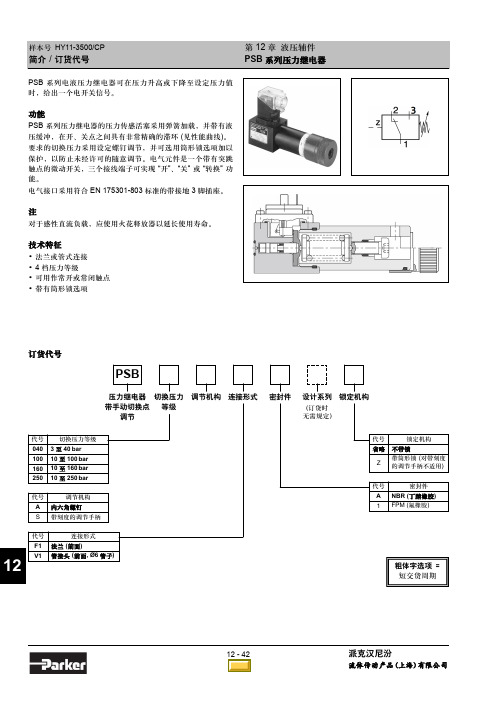
性能曲线 / 电气接口
开关切换压力差 PSB040
第 12 章 液压辅件 PSB 系列压力继电器
PSB100
上升切换点压力 pVO / bar
上升切换点压力 pVO / bar
PSB160
下降切换点压力 pVU / bar
粗体字选项 = 短交货周期
NG06 安装尺寸
NG10 安装尺寸
12
12 - 46 目录
派克汉尼汾
流体传动产品 (上海) 有限公司
代号 A S
调节机构 内六角螺钉 带刻度的调节手柄
12
代号 F1 V1
连接形式 法兰 (前面) 管接头 (前面, Ø6 管子)
代号 省略
Z
锁定机构 不带锁 带筒形锁 (对带刻度 的调节手柄不适用)
代号 A 1
密封件 NBR (丁腈橡胶) FPM (氟橡胶)
粗体字选项 = 短交货周期
12 - 42 目录
下降切换点压力 pVU / bar
派克汉尼汾
流体传动产品 (上海) 有限公司
样本号 HY11-3500/CP
安装尺寸
PSB*F1*型
第 12 章 液压辅件 PSB 系列压力继电器
PSB*V1*型
12 - 45 目录
12
派克汉尼汾
流体传动产品 (上海) 有限公司
样本号 HY11-3500/CP
PSB 压力继电器用中间转接板
中间转接板技术参数
说明
第 12 章 液压辅件 PSB 系列压力继电器
订货代号 H06PSB-994 H10PSB-996 H06PSB-993 H10PSB-995
上海西门子开关 产品介绍 说明书

■ 上海西门子开关有限公司2的严格管理不仅贯穿于内部生产的各个流程,同时延伸至对供应商的日年在闵行经年底公司二期厂房扩建工程的竣平方米,体现了西门子根植于中国、长期服务于中国客户的信心和承诺。
2004年研发中心作为西门子输配电全球研发中心的组成部分,可同步共享西门子最新的技术和资源。
通过预测客户的需求,开发质量稳定可靠的创新型产品和为客户度身定制方案,使客户的业务增值。
一支反应迅速、装备精良、经验丰富的售后服务队伍和遍布全国的服务网点构成了公司一套高效的现场服务应对系统,负责指导产品现场安装和操作,并承诺在最短时间内对紧急情况作出应对,将客户的断电年位列上海市年被上海市电器行业协会评为行业名优产品。
公司因其良好的商业信誉被评为“守合同重信而被电气时代以及专3AH3及面向全球同步发售所有产品均在西安高压电器研究所通过型式试验,确保产品的运行安全和操作人员的人身安全。
目 录ContentsSiemens Switchgear Ltd., Shanghai (SSLS) is a joint venture of Siemens Ltd., China (SLC) and Shanghai Power Transmission & Distribution Company, holding the manufacturing license to apply the latest tech-nology of Siemens vacuum circuit-breaker and medium voltage switchgear in P. R. China.Since established in 1993, relying on Siemens powerful resources and internal boundless cooperation, SSLS has provided reliable products, first-class service and innovative solutions for more than two thousand key projects both for domestic and overseas. SSLS has established a good reputation and leading position in China due to its large contribu-tion to the technique innovation and development of local switchgear industry.SSLS is a market oriented company with commitment to customers’satisfaction and to fulfill the demands for the medium voltage switchgear, with high quality and excellent reliability, by means of dynamically intro-ducing and constantly developing the applicable technique and prod-ucts to the local market. Customer’s success is our first priority. We pledge to provide the most value-added product and service, promise on-time delivery, and establish solid business partner relationship with customers, in result to create the maximum value for our customers.SSLS began to implement the customer-oriented quality management early in1996, and established a comprehensive quality management system in 2004 integrated with ISO9001, ISO14001 and OHSAS18001. The company utilizes the highly sophisticated machines and testing fa-cilities in production process. The high qualification of operators along with continuous in process quality control guarantee our well established and high quality standards at all times. The strict quality control is not only carried out throughout entire production processes, but also ex-tended to the daily management of our suppliers. We take environment protection as our social responsibility; meanwhile closely look after employees’ occupational safety and health.To meet the growing marketing demands, a modern factory was built up in Minhang Economic & Technological Development Zone in 2004. With the completion of second phase expansion at the end of 2006, the land plot increased to 50000sqm and shop floor to 23000sqm, which em-bodies Siemens’ commitment to root in China and serve long-term for Chinese customers.According to company’s strategy to create more competence and shorter time-to-market, SSLS R&D center was established in 2004. R&D cen-ter closely integrates into the Siemens PTD global R&D network, could share the latest Siemens technique and resources in-phase. By pre-dicting the market needs, SSLS fosters R&D in developing reliable and innovative products and tailored solutions to add value for customer’s business.Siemens switchgear has an effective system of on-site servicing from a quick-respondent, well-equipped and rich experienced field service team and a network setup all over China. The team is responsible for the guidance of on-site installation and operational safety, commit to re-spond to emergency calls within the shortest possible time and to mini-mize down time.SSLS was ranged as the Top 500 Revenue of Industrial Companies in Shanghai 7 years in row since 2000. The products won the title of Shang-hai Reputed Product 4 years in row since 2003. The company was awarded as “Good Credit Enterprise” due to its high commercial credit, and won the title of “Top 10 Fast-growing Companies in China Electric Industry” in 2006 due to over 30% increase of sales revenue continu-ously over the past three years.PRODUCT INTRODUCTIONSSLS provides air insulated Switchgear rated from 7.2 to 24kV with type 8BK20, 8BK30, 8BK40 and specially designed for Chinese market in 2007 NXAIR S, and vacuum circuit breakers type 3AH3, 3AH5, 3AH2-EP as well as SION, the latest generation of Siemens VCB synchro-nously selling world wide.All products are type tested in XIHARI to ensure the safety of personnel and operation.公司简介Company Introduction■产品介绍3■ 上海西门子开关有限公司4● Draw-out section and access door fully inte-grated interlock system.● Safe and easy draw-out section movementbehind closed cubicle door.● Easy draw-out section transfer or exchange,using central service truck, independent of floor quality.● Earthed metal partitions and shutters.● Connection of HV cables is available from front or rear part of the panel optionally.● Back-to-back or face-to-face designs available for double bus-bar design.●Reinforced insulation which fulfills Chinese system and local climate.●Direct line-up with 8BK30 Vacuum ContactorSwitchgear.● 可移开部分与柜门之间有可靠的联锁● 前门关闭后,能够很安全而且容易地移动可移开部分● 先进的中置式结构,使用专门的小车能够方便地搬运或更换可移开部分,不受现场地面平整度的限制● 金属隔板与活门均接地● 根据用户需要,可由前门或开关柜的后部进行电缆接线● 开关柜可以面对面布置,也可以背靠背布置(双母线回路)●加强了绝缘,更适合中国电力系统和气候● 可直接与8BK30型开关柜(F - C 回路)联接供电典型客户上海供电局北京供电局兰溪电厂秦皇岛港口宁波小港纸业兰州石化TYPICAL CUSTOMER Shanghai PSBBeijing PSBLanxi Power PlantQinghuangdao HarborNingbo Xiaogang Paper MillLanzhou Petro 产品特点SPECIFIC FEATURES 电气技术数据 ELECTRICAL DATA (MAXIMUM VALUES )8BK20 Switchgear with Draw-Out Circuit-Breakers, Air-Insulated, Metal Clad8BK20型金属封闭/铠装可移开式空气绝缘断路器柜■ 产品介绍5● Draw-out section and door integrated in the inter-lock system.● Minimal space requirement.● Vacuum contactor and HVHRC fuses on draw-outsection. Vacuum contactor is able to operate fre-quently due to its long mechanic life-1 millionoperations.● Draw-out section easily to move inside the cubicle.● Cable connection in front of cubicle.● Directly line-up with circuit-breaker panel of type 8BK20.● Special wheels on bottom of draw-out section provide an easy movement during in and out the cubicle.● Reinforced insulation to meet Chinese system andlocal climate.● 可移开部分与室门之间装有可靠的联锁装置● 占用空间少● 可移开部分装有真空接触器和高压限流熔断器。
武汉保尔富产品手册
目录1.罐下采样器 (1)2.浮动出油装置 (6)3.油罐自动切水器 (9)4.油罐油品随位调合旋转喷头 (15)5.密闭取样器系列 (18)6.管道采样器系列 (44)1.罐下采样器1.1.引言为了解决储罐内液体采样繁琐的问题,我公司根据国家标准GB/T4756-1998《石油液体手工取样法》检验的规定,结合多年采样器的生产实践经验研制出的PTBS型系列罐下采样器产品,深受用户好评。
1.2.产品优势1)所采取的油样准确性高;2)采用柔性连接技术,从而减少了罐内液体扰动对浮臂的冲击力量,延长了罐内装置的使用寿命。
3)操作简单、方便:采样工不需上罐,这样既减轻了采样工人的劳动强度又保证了安全,特别是在气候恶劣条件下,更能显示其优越性。
4)自动化程度高,节省采样时间,提高工作效率。
5)操作箱一体化设计,便于用户操作、安装、维修。
6)取样无残留,取样嘴无滴漏。
7)苯等有毒介质罐均为密闭耐压玻璃瓶取样,确保采样工的健康,无安全之忧。
1.3.产品型号1)PTBS-K型:用于内浮顶罐、外浮顶罐2)PTBS-X型:用于拱顶罐、内浮顶罐、外浮顶罐;3)PTBS-H型:用于无搅拌设备的拱顶罐、内浮顶罐、外浮顶罐;4)PTBS-I型:专门用于无搅拌设备的矮型拱顶罐5)PTBS-G型:专门用于有搅拌设备的拱顶罐及内浮顶罐,在满罐条件下取顶部、上部、中部、下部、底部、出口样。
1.4.产品结构图1.5.工作原理采样器装置所采用的结构形式能完全准确无误地保证采样法和取样位置规定的要求。
采样器装置是将三根(上、中、下)采样管固定在支撑管上,一根采上部油样,一根采中部油样,另一根采下部油样,支撑杆上端连浮标,下端固定在支座上。
当液面升降时,浮标随之浮动,采样管亦随之升降,因此三根采样管的开口高度始终保持在规定的采样位置。
1.6.适用范围适用介质范围:石脑油、汽油、煤油、柴油、原油、蜡油、沥青、化工原料等采用形式:相对点、定点采样、相对点或定点的混和液均质采样。
Real Time Automation 460PSBC-NNA4 产品介绍说明书

460PSBC-NNA4CONTACT US!1-800-249-1612 Real Time Automation GatewaysA Solution, A Philosophy, the RTA Way. We understand the long hours spent on a factory floor and thepressure to keep a line running and product flowing. That’s how Real Time Automation came to be. Youwant easy-to-use solutions where the hardest part is to open the box. You need customer support secondto none. If you get all that and a fun customer experience all the better. Thirty years later, our mission remains the same: To move your data where you need it, when you need it, and how you need it.Get Your BACnet/IP Server Devices Connected to a PROFINET IO Controller overWi-FiThe 460PSBC moves data between a network of up to 32 BACnet/IP servers and a PROFINET IO controller using Wi-Fi IEEE 802.11 b/g/n at 2.4GHz with AES encryption 128-bit.With the 460PSBC, you are making a direct connection between PROFINET IO data and your BACnet/IP servers.How Do I Use the 460PSBC-NNA4 in My Application?BACnet/IP server data will be mapped into 10 PROFINET IO slots. Each Slot will be assigned a data type and consist of up to 128 bytes of data, This data is mapped to and from BACnet/IP analog and binary objects.It’s really that simple. Need to modify your data as it passes from one protocol to the other? No problem. Each data mapping you apply can be modified with up to three mathematic functions. Add 4 to a value, multiply by 4 and divide by 10 with ease.Why Use Real Time Automation as a Gateway Supplier?While there are certainly other companies offering protocol gateways, there is no one who provides the level of support and service that you receive from RTA. When you call, a live person answers the phone. When you talk with sales, you will get honest answers and recommendations. When you get support, it is from an engineer who had a hand in the product’s development, and support doesn’t require a ticket or 24-hour wait.FEATURES •Fully configurable PROFINET device •Supports up to 1280bytes of data in each direction on PROFINETIO•Fully configurable BACnet/IP client •BACnet/IP supports device, binary I/O/V,analog I/O/V, multi-state I/O/V, and character string valueobject types•Effortless Browser Based Configuration, no programmingsoftware is required •Simple data translation allows you tomanipulate data as itpasses between protocols• Guaranteed Stock •5-Year HardwareWarrantyReal Time Automation, Inc.************************** - 1-800-249-1612Made in theU.S.A.Always InStockReady toShipExpertSupportProfinet IO ServerMaximum Number of Slots 10 Slots in, 10 Slots out Slot Data Segment Sizes8, 16, 32, 64 or 128 BytesEach Slot Can be Defined for a Single Data Type of Int8, int16, int32, int64, UInt8, Uint16, Uint32, Uint64, float, double, binary8, binary16 or binary32,Short String Total Data Supported in Each Direction1280 Bytes Maximum Profinet IO Controller Connections 1String Support 1 string per slotBACnet/IP Client Operation ModeBACnet/IP ClientSupported Object Types Device, BI/BO/BV, AI/AO/AV, MI/MO/MV, Character String ValueSupported Service CodesRead Property-A, Read Property Multiple-A, Write Property-A, Write Property Multiple-A, Device Dynamic Binding-A Maximum Connections32Number Read/Write Scan Lines per Device 200 Total - 100 reads & 100 writes Scan Line SupportUp to 128 Objects INCLUDED WITH GATEWAY 3’ power cable with flying leads5-year hardware warrantyIPSetup software – automatically locates RTA gateway on the networkUnlimited firmware feature upgrades for lifeCAT5 crossover cable for direct connection to PC during programming Complete, unlimited access to our industry leading support staff ManualELECTRICAL / ENVIRONMENTALDC Input Voltage 12-24 VDC .Maximum Baud Rate 115K baud Operating Temperature -40 C to 85 C Certification RoHS-Compliant, UL, CUL, CE Approvals ENCLOSURE / HARDWARE Size 3.88" x 2.57" x 1.06" Weight 5.5 oz Enclosure Type Anodized Aluminum Mounting Din rail or panel mount LEDs Power LED & 2 general purpose LEDs on side GATEWAY FEATURES & FUNCTIONSAlarming Set <, <=, >, >=, ==, !=, and change-of-state ruleson any data moving through the gateway. If alarmrule is triggered an email notification can be sent. Gateway SecurityYou can configure up to 9 different users access todiagnostic and configuration screens. Translation TableAllows for data manipulation during protocol translation. Scaling and other data format changes can occur in the gateway.Status and CountersProtocol specific status, counters, and error messages are accessible within the gateway’s diagnostics page. They can also be delivered to a connected device.NOT EXACTLY WHAT YOU WERE LOOKING FOR? Real Time Automation offers a full line of gateway products. Give us a call at 1-800-249-1612. Or, check out a listing at/products . We also offercustomizations for unique applications.Diagnostic Logging PageAllows users to see and log start up sequences, protocol specific messages & error messages.CATALOG # DESCRIPTION460PSBC-NNA4Connects a PROFINET IO controller with up to 32 BACnet/IP servers over wireless。
- 1、下载文档前请自行甄别文档内容的完整性,平台不提供额外的编辑、内容补充、找答案等附加服务。
- 2、"仅部分预览"的文档,不可在线预览部分如存在完整性等问题,可反馈申请退款(可完整预览的文档不适用该条件!)。
- 3、如文档侵犯您的权益,请联系客服反馈,我们会尽快为您处理(人工客服工作时间:9:00-18:30)。
PSB系列离心机使用说明书(2003年第1版)张家港市中南化工机械有限公司制造厂敬告用户:1.因用户选型不当而造成离心机不能正常使用,或不能达到预期目的,如型号、型式、规格选择不当;2.用户不按规定的范围使用离心机。
例如将一般用途离心机用于易燃、易爆场合;将无防腐措施的离心机用于处理强腐蚀物料;将1Cr18Ni9Ti材质(接触物料部分的材料)的离心机用于处理含卤素元素的物料等;3.不按规定的操作规程运行。
例如反向运转、非正常制动、超负荷运转、超速运转、违反规定的工作程序运行等;4.不按产品使用说明书中的要求安装、调试、使用、维护离心机或自行修改离心机的零件或增加附属装置;5.操作及维护人员未经上岗培训;6.不及时排除故障,不及时报废失效的离心机;由以上因素而造成离心机不能正常使用或发生事故及由此而造成的损失,本公司概不负责。
特郑重声明。
本公司将对本手册中的打印错误、与最新资料不符之处、技术改进等随时作出必要改动,这些改动不再事先通知,将会编入新版说明书中。
用户实际所购离心机按随机文件中的使用说明书为准。
2003年第1版目录1. 产品概述2. 适用范围3. 技术参数4. 工作原理5. 结构简述6. 环境、运输、贮存要求7. 机器的安装及调整8. 机器的使用9. 机器常见故障及其排除方法10. 离心机安全使用规范11. 质量保证期1产品概述PSB型系列离心机是平板式人工上卸料间歇操作过滤离心机,该系列离心机结构简单,性能可靠,操作、维修方便,过滤时间可随意掌握,滤渣能充分洗涤,固相颗粒不被破坏,滤袋清洗方便。
机器采用密闭结构,密封处采用硅橡胶或氟橡胶密封;配置防爆电机、变频器、能耗制动等装置可实现密闭防爆要求。
2适用范围PSB型系列离心机适用于含固相颗粒的悬浮液介质的洗涤和固、液相分离,应用极其广泛,常用于石膏,硫铵、芒销、硫酸铁、硫酸铜、硫酸镍、氯化钾、醋酸、硼砂、苏打、橡胶添加剂、染料、淀粉、制糖、维生素、抗生素、除草剂、驱虫剂、铜、锌、铝、排酸石膏、金属精制、净水污泥、下水污泥及其它各种药品的处理等。
对有些介质还需经物料分析和试验,确定其适用性。
如果采用中速时通过外壳盖上的进料管加料,分离介质应是均匀的和连续的,在管道中流动性较好。
用户在选型时必须按分离介质的理化性质(介质种类、温度、浓度、粘度、固相物的滑移性、对固相颗粒的要求、允许的固相滤渣中的剩余液相等)、分离过程中和所处的生产环境中的防腐和防爆要求,确定离心机的型号和型式,以达到预期目的及安全要求。
需要说明的是,对于离心机的生产能力,与所分离物料的理化性质(如粘度、流动性、含固量、滤饼的硬度)、生产工艺、操作工人的熟练程度、离心机启动和制动方式、滤布规格型号的选用等有直接的关系。
比如,分离物料含固量低,加料时间也就长,或有防爆要求而采用能耗制动方式制动时间的延长等等因素都会加长每个工作循环的时间,从而影响其产量。
随着工艺流程的完善和工人操作的熟练,其生产能力比试产时有一定的提高。
3技术参数上表中有(/)处为同一规格的离心机的两种型式。
用户在选型时应注明。
4工作原理:PSB系列离心机,可在运转时加料,也可在转鼓停转时加料,在停转加料时必须控制好物料容积及重量,否则会产生跑液或过载。
物料在离心力作用下,趋向转鼓壁,液相经覆盖于鼓壁的过滤介质穿过鼓壁滤孔,趋向外壳内壁而落入底盘,径出液口排出。
而固相物料存留在转鼓内并可充分洗涤,从而完成固液分离,停机后打开外壳翻盖,人工将滤饼卸出,卸料完毕后,关上翻盖并锁紧即可开始第二工作循环。
5结构简述PSB型离心机主要有机体部件、平衡缸部件、主轴传动部件、转鼓部件及电机部件等组成。
结构简图见图一。
5.1机体部件:机体部件:分机座组件和机壳组件和防护罩组件。
机座组件:主要有底座、轴承座、出液管、减振器等组成。
底座为铸铁件,外包304板,底盘是作安装固定机壳、主轴传动装置、出液管、并能汇集液体。
机壳组件:由机壳、机壳盖等组成。
机壳盖上装有进料管、洗涤管、排气管和视镜,并用铰链与机壳连接,翻盖为整体翻转,配用两只平衡缸,翻盖轻便自如,清洗方便。
5.2平衡缸部件:平衡缸部件:由缸筒、活塞杆、活塞及弹簧等组成。
无需其它动力源,结构简单,翻盖轻便自如。
5.3主轴传动部件:主轴部件:主要有主轴、轴承座、轴承、轴承压盖、轴承衬套、主轴带轮等零件组成,采用螺纹连接固定于机体部件上。
图一、离心机结构简图5.4转鼓部件:转鼓部件:主要有转鼓底、转鼓筒体及拦液板等组成。
转鼓部件采用焊接和铆接形式,部件通过动平衡校正后,靠中心锥孔与主轴锥端面配合紧固在主轴上。
5.5电机部件:电机部件:主要有电机、电机底板、电机托架、电机带轮(或离合器)及防护罩等组成。
5.6电控箱详见电器控制箱使用说明书。
5.7离心机的材料及结构配置PSB系列离心机标准的配置形式为:与物料相接触部分的材料为SUS304不锈钢材,机座材质为Q235,外露面采用304板材全包衬。
外壳翻盖上配置进料管、洗涤管、观察镜、照明灯孔。
采用变频调速,能耗制动。
PSB系列离心机选装配置:应用户要求,可以选定与物料相接触部分的材质,如316L、321、钛材、衬塑等,非物料接触部分也可采用全不锈钢制造。
其传动形式可以选择普通电机+变频器、防爆电机+变频器或电机配离合器等形式。
对于选装配置或特别要求,在订单中注明。
5.8需要说明的是:离心机只配置防爆电机,离心机整机并不防爆,对于有防爆要求的场合,用户在订货时应说明所分离的介质、防爆要求和等级,配置相应的装置和采取合适的措施来满足防爆要求。
6环境、运输、贮存要求6.1工作环境:温度0-40℃;空气相对湿度不大于85%。
6.2运输:离心机在装运过程中,不得翻滚和倒置,不得叠装,防止雨水侵入。
6.3搬运:离心机在搬运过程中必须按离心机重心位置进行铲运,铲运时尽量保持离心机水平,不得翻滚和倒置。
铲运部位为机座底平面。
6.4贮存:离心机应放置在温度0-40℃,空气相对湿度不大于85%,没有腐蚀性介质的遮避场所。
离心机在安装、使用前须有专人保管,以确保离心机的完好。
在运行前应由制造厂对离心机的技术状态和安装情况进行确认。
7机器的安装及调整7.1安装注意事项7.1.1机器安装前后必须注意保管,注意电机的防潮,要注意对电控系统的保护。
7.1.2铲运吊装时必须注意安全,以免机器受到碰撞而损坏。
7.1.3离心机安装必须水平,基准面为机座上平面(水平度≤3mm)。
7.1.4与离心机相邻安装的设备及其它装置与离心机之间应有足够的空间,以免机器工作时与之产生碰撞而使机器受到损坏或出现噪声,并利于对机器的检修和保养。
离心机的安装位置排布必须要充分考虑离心机使用和维修时所需要的空间。
在离心机主机的四周要有不小于1米的人行通道。
离心机主机的上方必须要有2米以上的装拆维修空间。
7.1.5该机为无基础型离心机,浇制离心机的安放基础时,必须做到坚实牢固,见图二。
应预先铺设电缆管道,其出口在电控箱和电机相邻的位置。
7.1.6机器一般为整机安装,不得拆卸,如确有必要,则装配后必须由制造厂技术人员对其进行确认。
图二、离心机安装基础图7.1.7离心机的安装基础必须水平,基础重量约为机器重量的3倍,基础除承受机器的静载荷外,尚需允许承受动载荷,如离心机高架安装,承重梁及操作平台由该工程设计部门负责。
7.1.8由于离心机在高速运转时有轻微振动,故与离心机连接的管道(进料管、出液管、洗涤管、排气管、电缆管等)必须柔性连接,连接处必须有可靠的密封或绝缘装置,确保无渗漏和安全用电。
外接出液管径不得小于机器出液管直径,并不得有死弯、堵塞,管道布置应低于出液管口高度,并有一定的高度差,以便出液畅通。
管道接口尺寸:7.1.10根据分离物料的特性,选择合适的滤布型号按制造厂提供的滤袋制作图缝制滤袋,保证滤袋与转鼓筒体有较好的贴合性。
7.1.11按照PSB系列离心机的电气控制原理图,见图三。
由电气技师将电气线路接好。
以待离心机的运转和调整。
7.1.12离心机安装完毕后,接通电动机电源,根据离心机机壳上所标注的旋转方向调整电机转向及三角带的张紧适度,准备试车运转。
7.2警告:7.2.1机器运转前必须把外壳盖盖好并锁紧!7.2.2机器运转时严禁打开外壳盖!7.2.3用户应根据所处理物料的性质来选择转鼓的材质!防止腐蚀或过快腐蚀。
7.2.4离心机主机上的进料管、洗涤管、排气管、及排液管与外界的联接严禁采用刚性联接!以免影响主机本身的减振系统和损坏机器。
8机器的使用8.1电源及电机a.电源:380V;50Hz;电机功率见技术参数。
b.电动机必须接地可靠,确保用电安全。
c.电机转向必须按铭牌所示方向旋转,不得反转!d.离心机与动力源的连接按电气控制原理图(图三)进行接线,配用电器型号、规格按电机功率、额定电流等参数,按有关电气控制标准配置,以防止电的过载,并能有效实现过载保护。
8.2拖动和控制a.离心机的转鼓采用普通或防爆交流电动机拖动,变频器或离合器起动方式。
b.制动采用变频能耗制动或手动制动形式。
图三、电气控制原理图8.3操作8.3.1开机前的准备工作:a、使用前应将作业场所清理干净,以消除作业障碍,并检查以下各部位。
b、制动应灵活可靠;c、用手转动转鼓不得有咬死或卡死现象;d、各部位螺栓应紧固不得有松动现象;e、检查滤袋是否符合物料脱液要求,不得有破损;f、旋转方向是否与指示牌方向一致。
g、机壳盖翻转应灵活可靠。
h、检查各连接处是否正确、可靠。
8.3.2启动与操作:8.3.2.1变频起动(1)、接通电源,按启动按钮,由变频器控制电机按预先设置好的运行参数(启动时间、速度段、制动时间、转速显示等)运行(也可手动控制),离心机逐渐增速。
(2)、当离心机至设定的加料转速时,打开进料阀开始进料,同时将一部分液相滤出。
根据需要也可在起动前先加料,加料量由操作者根据离心机容积及容量目测或估测。
待加料达到限定量后,关闭进料阀。
加料时必须注意:滤饼的容积和重量都不能超过规定。
当滤饼密度较大时,必须保证其滤饼重量不得大于规定的装料重量,以免出现危险;当滤饼密度较小时,必须保证其滤饼体积不得大于规定的装料容量,以免料浆溢出。
(3)、如滤饼需要洗涤,则打开洗涤阀,对滤饼进行洗涤,同时将一部分洗涤液滤出(洗涤时间根据工艺要求而定)。
(4)、离心机升至额定转速,对滤饼进行进一步脱液。
(5)、脱液完毕后,按停止按钮,离心机进行能耗制动,直至转鼓停止转动。
(6)、松开锁紧手柄打开离心机外壳翻盖,人工将滤饼卸出。
卸料时应注意对滤布的保护,不得损坏,以免下次分离时造成跑料和振动。
(7)、检查滤袋是否完好,并重新铺设好,盖上外壳翻盖并锁紧手柄,开始第二工作循环。
(8)、注意事项变频器内部设置好升速(启动)时间及降速(制动)时间,用户可根据实际情况作适当调整,但必须由专业人员操作设置。