3GPP协议36.843
最新LTE中文协议LTE_3GPP_36.213-860(中文版)
3GPP TS 36.213 V8.6.0 (2009-03)3rd Generation Partnership Project;Technical SpecificationTechnical Specification Group Radio Access Network;Evolved Universal Terrestrial Radio Access (E-UTRA);Physical layer procedures(Release 8)The present document has been developed within the 3rd Generation Partnership Project (3GPP TM) and may be further elaborated for the purposes of 3GPP.134KeywordsUMTS, radio, layer 1 3GPPPostal address3GPP support office address650 Route des Lucioles –Sophia AntipolisValbonne – France Tel.: +33 4 92 94 42 00 Fax: +33 4 93 65 47 16InternetCopyright NotificationNo part may be reproduced except as authorized by written permission.The copyright and the foregoing restriction extend to reproduction in all media.© 2009, 3GPP Organizational Partners (ARIB, ATIS, CCSA, ETSI, TTA, TTC).All rights reserved.UMTS™ is a Trade Mark of ETSI registered for the benefit of its members3GPP™ is a Trade Mark of ETSI registered for the benefit of its Members an d of the 3GPP Organizational Partners LTE™ is a Trade Mark of ETSI currently being registered for the benefit of its Members and of the 3GPP Organizational PartnersGSM® and the GSM logo are registered and owned by the GSM Association6Contents7Foreword (5)81 ................................................................ Scope 6 92 ........................................................... References 6 103 .............................. Definitions, symbols, and abbreviations 7 113.1 .......................................................... Symbols 7 123.2 .................................................... Abbreviations 7 134 ........................................... Synchronisation procedures 8 144.1 ...................................................... Cell search 8 154.2 ........................................... Timing synchronisation 8 164.2.1 ........................................ Radio link monitoring 8 174.2.2 ................................... Inter-cell synchronisation 8 184.2.3 .............................. Transmission timing adjustments 8 195 ............................................................. Power control 9205.1 ............................................. Uplink power control 9215.1.1 ............................... Physical uplink shared channel 9225.1.1.1 ............................................ UE behaviour 9235.1.1.2 .......................................... Power headroom 12245.1.2 .............................. Physical uplink control channel 12255.1.2.1 ............................................ UE behaviour 12265.1.3 .................................... Sounding Reference Symbol 14275.1.3.1 ............................................ UE behaviour 14285.2 ........................................ Downlink power allocation 15295.2.1 ............ eNodeB Relative Narrowband TX Power restrictions 16306 .............................................. Random access procedure 16316.1 ................ Physical non-synchronized random access procedure 16326.1.1 ....................................................... Timing 17336.2 ............................................ Random Access Response Grant 1347 ................. Physical downlink shared channel related procedures 18357.1 .. UE procedure for receiving the physical downlink shared channel 19367.1.1 ................................. Single-antenna port scheme 21377.1.2 ................................... Transmit diversity scheme 21387.1.3 ...................................... Large delay CDD scheme 22397.1.4 ..................... Closed-loop spatial multiplexing scheme 22407.1.5 ...................................... Multi-user MIMO scheme 22417.1.6 ......................................... Resource allocation 22427.1.6.1 .............................. Resource allocation type 0 22437.1.6.2 .............................. Resource allocation type 1 23447.1.6.3 .............................. Resource allocation type 2 24457.1.7 ..... Modulation order and transport block size determination 25467.1.7.1 .......................... Modulation order determination 25477.1.7.2 .................................. Transport block size determination 2487.1.7.2.1Transport blocks not mapped to two-layer spatial multiplexing 27 497.1.7.2.2Transport blocks mapped to two-layer spatial multiplexing 32507.1.7.2.3 ............. Transport blocks mapped for DCI Format 1C 33517.1.7.3 .......... Redundancy Version determination for Format 1C 33527.2UE procedure for reporting channel quality indication (CQI), precoding matri 537.2.1 ................... Aperiodic CQI/PMI/RI Reporting using PUSCH 36547.2.2 .................... Periodic CQI/PMI/RI Reporting using PUCCH 40557.2.3 ................... Channel quality indicator (CQI) definition 46567.2.4 .................. Precoding Matrix Indicator (PMI) definition 48577.3 .............................. UE procedure for reporting ACK/NACK 49588 .................... Physical uplink shared channel related procedures 52598.1 ....................... Resource Allocation for PDCCH DCI Format 0 54608.2 ............................................ UE sounding procedure 55618.3 ................................................... UE ACK/NACK procedure 5628.4 ....................................... UE PUSCH Hopping procedure 58638.4.1 ....................................... Type 1 PUSCH Hopping 59648.4.2 ....................................... Type 2 PUSCH Hopping 59658.5 .................................... UE Reference Symbol procedure 60668.6Modulation order, redundancy version and transport block size determination 678.6.1 ....... Modulation order and redundancy version determination 60688.6.2 .......................... Transport block size determination 61698.6.3 ................ Control information MCS offset determination 61708.7 .................................... UE Transmit Antenna Selection 63719 ......................... Physical downlink control channel procedures 64729.1UE procedure for determining physical downlink control channel assignment 64 739.1.1 ................................. PDCCH Assignment Procedure 64749.1.2 ................................. PHICH Assignment Procedure 65759.2 ......................... PDCCH validation for semi-persistent scheduling 67610 .......................... Physical uplink control channel procedures 677710.1UE procedure for determining physical uplink control channel assignment 67 7810.2 .......................................... Uplink ACK/NACK timing 7279Annex A (informative): ................. Change history 74808182Foreword83This Technical Specification (TS) has been produced by the 3rd Generation84Partnership Project (3GPP).85The contents of the present document are subject to continuing work within 86the TSG and may change following formal TSG approval. Should the TSG modify the 87contents of this present document, it will be re-released by the TSG with an88identifying change of release date and an increase in version number as follows: 89Version x.y.z90where:91x the first digit:921 presented to TSG for information;932 presented to TSG for approval;943 or greater indicates TSG approved document under change95control.96y the second digit is incremented for all changes of substance, i.e.97technical enhancements, corrections, updates, etc.98z the third digit is99incremented when editorial only changes have been incorporated in the 100document.1011021 Scope103The present document specifies and establishes the characteristics of the 104physicals layer procedures in the FDD and TDD modes of E-UTRA.1052 References106The following documents contain provisions which, through reference in this 107text, constitute provisions of the present document.108References are either specific (identified by date of publication, 109edition number, version number, etc.) or non-specific.110For a specific reference, subsequent revisions do not apply.111For a non-specific reference, the latest version applies. In the 112case of a reference to a 3GPP document (including a GSM document), a non-113specific reference implicitly refers to the latest version of that document 114in the same Release as the present document.115[1] 3GPP TR 21.905: “Vocabulary for 3GPP Specifications”116[2] 3GPP TS 36.201: “Evolved Universal Terrestrial Radio117Access (E-UTRA); Physical Layer – General Description”118[3] 3GPP TS 36.211: “Evolved Universal Terrestrial Radio119Access (E-UTRA); Physical channels and modulation”120[4] 3GPP TS 36.212:121“Evolved Universal Terrestrial Radio Access (E-UTRA);122Multiplexing and channel coding”123[5] 3GPP TS 36.214: “Evolved Universal Terrestrial Radio124Access (E-UTRA); Physical layer –Measurements”125[6] 3GPP TS 36.101: “Evolved Universal Terrestrial Radio126Access (E-UTRA); User Equipment (UE) radio transmission and127reception”128[7] 3GPP TS 36.104: “Evolved Universal Terrestrial Radio129Access (E-UTRA); Base Station (BS) radio transmission and130reception”131[8] 3GPP TS36.321, “Evolved Universal Terrestrial Radio Access 132(E-UTRA); Medium Access Control (MAC) pro tocol specification”133[9] 3GPP TS36.423, “Evolved Universal Terrestrial Radio Access 134(E-UTRA); X2 Application Protocol (X2AP)”135[10] 3GPP TS36.133, “Evolved Universal Terrestrial Radio136Access (E-UTRA); Requirements for support of radio resource137management”138[11] 3GPP TS36.331, “Evolved Universal Terrestrial Radio139Access (E-UTRA); Radio Resource Control (RRC) protocol140specification”1413 Definitions, symbols, and abbreviations 143 3.1 S ymbols144 For the purposes of the present document, the following symbols apply: 145 DL RB N Downlink bandwidth configuration, expressed in units of 146RB sc N as defined in [3]147 UL RB N Uplink bandwidth configuration, expressed in units of 148RB sc N as defined in [3]149 UL sym b N Number of SC-FDMA symbols in an uplink slot as defined 150in [3]151 RB sc N Resource block size in the frequency domain, expressed 152as a number of subcarriers as defined in [3]153 s T Basic time unit as defined in [3]1543.2 A bbreviations156For the purposes of the present document, the following abbreviations apply. 157ACK A cknowledgement158BCH B roadcast Channel159CCE Control Channel Element160CQI C hannel Quality Indicator161CRC Cyclic Redundancy Check162DAI D ownlink Assignment Index163DL Downlink164DTX D iscontinuous Transmission165EPRE Energy Per Resource Element166MCS M odulation and Coding Scheme167NACK Negative Acknowledgement168PBCH Physical Broadcast Channel169PCFICH Physical Control170Format Indicator Channel171PDCCH Physical Downlink Control Channel172PDSCH Physical Downlink Shared Channel173PHICH Physical Hybrid ARQ Indicator Channel 174PRACH Physical Random Access Channel175PRB Physical Resource Block176PUCCH Physical Uplink Control Channel177PUSCH Physical Uplink Shared Channel178QoS Q uality of Service179RBG R esource Block Group180RE Resource Element181RPF R epetition Factor182RS Reference Signal183SIR S ignal-to-Interference Ratio184SINR Signal to185Interference plus Noise Ratio186SPS C-RNTI Semi-Persistent Scheduling C-RNTI187SRS S ounding Reference Symbol188TA Time alignment189TTI T ransmission Time Interval190UE User Equipment191UL Uplink192UL-SCH Uplink Shared Channel193VRB V irtual Resource Block1944 同步过程1954.1 小区搜索196小区搜索是指UE在小区中获取时间和频率同步并检测小区物理层Cell ID的过程。
3gpp报告
3GPP报告介绍3GPP(第三代合作伙伴计划)是一个致力于推动全球移动通信技术发展的国际标准化组织。
该组织的成员包括全球各大移动通信运营商、设备制造商和研究机构。
3GPP定期发布报告,总结和分析移动通信技术的发展趋势和最新成果。
报告结构3GPP报告通常由以下几个部分组成:1. 引言在报告的引言部分,会介绍3GPP组织的背景和目标,以及本次报告的撰写目的。
同时还会提供一些背景知识,帮助读者更好地理解后续内容。
2. 标准化进展这一部分会详细介绍3GPP在移动通信技术标准化方面的最新进展。
包括新发布的标准版本、对现有标准的修订和更新、以及相关的技术规范和测试方法等。
这些标准化工作对于推动全球移动通信技术的发展具有重要意义。
3. 技术趋势分析在技术趋势分析部分,报告会对当前和未来几年内的移动通信技术趋势进行预测和分析。
这包括对新技术的评估和展望,以及对行业发展方向的研究和探讨。
这些分析对于决策者和从业人员来说都具有重要的参考价值。
4. 业务应用案例在报告的业务应用案例部分,会列举一些具体的业务场景和应用案例,展示移动通信技术在不同领域的应用。
这些案例旨在帮助读者更好地理解移动通信技术在实际应用中的价值和潜力。
5. 指导建议在报告的最后,会给出一些指导建议,帮助各方面的利益相关者更好地应对移动通信技术发展所面临的挑战和机遇。
这些建议可能包括政策制定、产业投资、技术研发等方面的建议。
总结3GPP报告是全球移动通信行业的重要参考资料,它记录和总结了移动通信技术的发展动态和趋势。
通过详细介绍标准化进展、技术趋势分析、业务应用案例和指导建议,报告为决策者、从业人员和学术界提供了重要的参考和指导。
我们相信,通过3GPP的不断努力和创新,移动通信技术将继续推动人类社会的进步和发展。
以上是关于3GPP报告的简要介绍和结构分析。
希望本文对您理解3GPP报告的重要性和价值有所帮助。
感谢阅读!。
标准协议之3GPP标准协议

标准协议之3GPP标准协议引言第三代移动通信(3G)技术的发展,为高速数据通信提供了基础支撑,3G通信技术的标准化是实现互联网与移动通信的深度融合的关键。
为此,诸多组织纷纷开展研究,提出了各自的3G通信标准协议,3GPP标准协议就是其中最具代表性的一种。
本文将对3GPP标准协议进行详细介绍。
一、3GPP标准协议的概述3GPP(3rd Generation Partnership Project),即第三代移动通信合作伙伴计划,是一个负责第三代移动通信标准制定的国际标准化组织。
它成立于1998年,由欧洲电信标准化组织(ETSI)、日本电信技术委员会(ARIB)和中国电信技术标准化委员会(CCSA)三个组织联合发起,后增加了韩国电信技术委员会(TTC)和美国电子工程师学会(IEEE)等组织参与。
目前,该组织已经成为了全球3G移动通信标准的主要制定组织之一。
3GPP标准协议是3GPP制定的通信标准协议。
它包含了无线接入技术、网络及服务层技术等方面的规范和标准。
目前,3GPP已经发展到了第16个版本(所谓的Release 16),在这些版本中,3GPP不断更新、完善和调整标准协议,以满足不断增长的通信技术需求。
二、3GPP标准协议的技术特点1. 广泛适用性3GPP标准协议是基于全球3G技术制定的,因此在全球范围内得到了广泛的应用。
目前,3GPP标准协议已成为全球最主要的移动通信技术标准之一。
2. 支持多种业务3GPP标准协议支持语音、短信、多媒体消息、互联网接入、视频通信等多种业务,能够满足用户的多样化需求。
3. 高速数据通信3GPP标准协议支持多种高速数据通信技术,如CDMA2000、HSPA、LTE等,可以提供更加快捷、高速的数据传输服务。
近年来,随着5G技术的逐渐普及,3GPP标准协议也在不断升级,以适应新时期的通信技术需求。
4. 具备可扩展性3GPP标准协议支持多种可扩展的技术和功能,这使得移动通信网络能够根据用户需求的增加而进行扩展和升级。
3gpp协议

3GPP协议1. 引言3GPP(第三代合作伙伴计划)是一个跨国合作组织,致力于制定和发展无线通信标准和技术。
3GPP协议是由该组织制定的一系列标准和规范,用于支持全球范围内的移动通信网络。
本文档将介绍一些常见的3GPP协议,包括LTE和5G等。
2. LTE协议LTE(Long-Term Evolution)是一种4G移动通信技术,它是3GPP协议中的一部分。
LTE协议定义了整个网络架构和通信协议层,包括物理层、数据链路层、网络层和应用层等。
•物理层:LTE物理层定义了信道、调制解调、传输和编码等。
它使用了OFDM(正交频分多路复用)和MIMO(多输入多输出)等技术,以提供高速数据传输和更好的信号质量。
•数据链路层:LTE数据链路层负责广播和多址接入,以及无线资源的调度和管理。
它使用了一种称为LTE无线接入接口的协议,用于无线资源的分配和调度。
•网络层:LTE网络层包括用户面和控制面,它负责用户数据的路由和传输,以及控制消息的传递。
LTE网络层使用IP协议进行数据传输,并提供QoS(服务质量)管理、移动性管理和安全性等功能。
•应用层:LTE应用层提供基于IP的应用服务,如VoIP(语音通信)、视频流媒体和互联网访问等。
3. 5G协议5G是下一代移动通信技术,也是3GPP协议的一部分。
5G协议在LTE的基础上进行了扩展和改进,以提供更高的数据传输速度、更低的延迟和更好的网络容量。
•物理层:5G物理层采用了新的技术,如更高的频率、更宽的频带和更高的MIMO级别等。
它可以支持更高的数据传输速率和更低的延迟。
•数据链路层:5G数据链路层引入了新的帧结构和调度算法,以提高网络的容量和效率。
它还支持更复杂的调度和编码技术,以适应不同的应用需求。
•网络层:5G网络层引入了网络切片(Network Slicing)的概念,以支持不同种类的应用和服务。
它还支持更灵活的移动性管理和安全性机制。
•应用层:5G应用层将继续提供基于IP的应用服务,并支持更高质量的多媒体传输和更低的延迟。
3gpp协议
3GPP TR 36.942 V9.0.1(2010-04)Technical Report3rd Generation Partnership Project;Technical Specification Group Radio Access Network; Evolved Universal Terrestrial Radio Access (E-UTRA);Radio Frequency (RF) system scenarios(Release 9)The present document has been developed within the 3rd Generation Partnership Project (3GPP TM ) and may be further elaborated for the purposes of 3GPP.The present document has not been subject to any approval process by the 3GPP Organizational Partners and shall not be implemented.This Specification is provided for future development work within 3GPP only. The Organizational Partners accept no liability for any use of this Specification. Specifications and reports for implementation of the 3GPP TM system should be obtained via the 3GPP Organizational Partners' Publications Offices.KeywordsLTE, Radio3GPPPostal address3GPP support office address650 Route des Lucioles - Sophia AntipolisValbonne - FRANCETel.: +33 4 92 94 42 00 Fax: +33 4 93 65 47 16InternetCopyright NotificationNo part may be reproduced except as authorized by written permission.The copyright and the foregoing restriction extend to reproduction in all media.© 2010, 3GPP Organizational Partners (ARIB, ATIS, CCSA, ETSI, TTA, TTC).All rights reserved.UMTS™ is a Trade Mark of ETSI registered for the benefit of its members3GPP™ is a Trade Mark of ETSI registered for the benefit of its Members and of the 3GPP Organizational PartnersLTE™ is a Trade Mark of ETSI currently being registered for the benefit of i ts Members and of the 3GPP Organizational Partners GSM® and the GSM logo are registered and owned by the GSM AssociationContentsForeword (6)1Scope (7)2References (7)3Definitions, symbols and abbreviations (8)3.1Definitions (8)3.2Symbols (8)3.3Abbreviations (8)4General assumptions (9)4.1Interference scenarios (10)4.2Antenna Models (10)4.2.1BS antennas (10)4.2.1.1BS antenna radiation pattern (11)4.2.1.2BS antenna heights and antenna gains for macro cells (11)4.2.2UE antennas (12)4.2.3MIMO antenna Characteristics (12)4.3Cell definitions (12)4.4Cell layouts (12)4.4.1Single operator cell layouts (12)4.4.1.1Macro cellular deployment (12)4.4.2Multi operator / Multi layer cell layouts (12)4.4.2.1Uncoordinated macro cellular deployment (13)4.4.2.2Coordinated macro cellular deployment (13)4.5Propagation conditions and channel models (14)4.5.1Received signal (14)4.5.2Macro cell propagation model – Urban Area (14)4.5.3Macro cell propagation model – Rural Area (15)4.6Base-station model (15)4.7UE model (17)4.8RRM models (18)4.8.1Measurement models (18)4.8.2Modelling of the functions (18)4.9Link level simulation assumptions (18)4.10System simulation assumptions (18)4.10.1System loading (18)5Methodology description (18)5.1Methodology for co-existence simulations (18)5.1.1Simulation assumptions for co-existence simulations (18)5.1.1.1Scheduler (18)5.1.1.2Simulated services (19)5.1.1.3ACIR value and granularity (19)5.1.1.4.1Uplink Asymmetrical Bandwidths ACIR (Aggressor with larger bandwidth) (19)5.1.1.4.2Uplink Asymmetrical Bandwidths ACIR (Aggressor with smaller bandwidth) (22)5.1.1.4Frequency re-use and interference mitigation schemes for E-UTRA (22)5.1.1.5CQI estimation (23)5.1.1.6Power control modelling for E-UTRA and 3.84 Mcps TDD UTRA (23)5.1.1.7SIR target requirements for simulated services (23)5.1.1.8Number of required snapshots (23)5.1.1.9Simulation output (23)5.1.2Simulation description (24)5.1.2.1Downlink E-UTRA interferer UTRA victim (24)5.1.2.2Downlink E-UTRA interferer E-UTRA victim (24)5.1.1.1Uplink E-UTRA interferer UTRA victim (24)5.1.2.4Uplink E-UTRA interferer E-UTRA victim (25)6System scenarios (25)6.1Co-existence scenarios (26)7Results (26)7.1Radio reception and transmission (26)7.1.1FDD coexistence simulation results (26)7.1.1.1ACIR downlink 5MHz E-UTRA interferer – UTRA victim (26)7.1.1.2ACIR downlink 10MHz E-UTRA interferer – 10MHz E-UTRA victim (27)7.1.1.3ACIR uplink 5MHz E-UTRA interferer – UTRA victim (29)7.1.1.4ACIR uplink 10MHz E-UTRA interferer – 10MHz E-UTRA victim (31)7.1.2TDD coexistence simulation results (34)7.1.2.1ACIR downlink 5MHz E-UTRA interferer – UTRA 3.84 Mcps TDD victim (34)7.1.2.2ACIR downlink 10MHz E-UTRA interferer – 10MHz E-UTRA TDD victim (36)7.1.2.3ACIR downlink 1.6 MHz E-UTRA interferer – UTRA 1.28 Mcps TDD victim (38)7.1.2.4ACIR uplink 5MHz E-UTRA interferer – UTRA 3.84 Mcps TDD victim (41)7.1.2.5ACIR uplink 10MHz E-UTRA interferer – 10MHz E-UTRA TDD victim (43)7.1.2.6ACIR uplink 10MHz E-UTRA interferer – 10MHz E-UTRA TDD victim (LCR frame structurebased) (45)7.1.2.7ACIR downlink 10MHz E-UTRA interferer – 10MHz E-UTRA TDD victim (LCR framestructure based) (46)7.1.3Additional coexistence simulation results (48)7.1.3.1ACIR downlink E-UTRA interferer – GSM victim (48)7.1.3.2ACIR uplink E-UTRA interferer – GSM victim (50)7.1.3.3Asymmetric coexistence 20 MHz and 5 MHz E-UTRA (51)7.1.3.4Impact of cell range and simulation frequency on ACIR (53)7.1.3.5Uplink Asymmetric coexistence TDD E-UTRA to TDD E-UTRA (54)7.1.4Base station blocking simulation results (56)7.2RRM (58)8Rationales for co-existence requirements (58)8.1BS and UE ACLR (58)8.1.1Requirements for E-UTRA – UTRA co-existence (58)8.1.2Requirements for E-UTRA – E-UTRA co-existence (59)9Deployment aspects (59)9.1UE power distribution (59)9.1.1Simulation results (60)10Multi-carrier BS requirements (62)10.1Unwanted emission requirements for multi-carrier BS (62)10.1.1General (62)10.1.2Multi-carrier BS of different E-UTRA channel bandwidths (63)10.1.3Multi-carrier BS of E-UTRA and UTRA (63)10.2Receiver requirements for multi-carrier BS (64)10.2.1General (64)10.2.2Test principles for a multi-carrier BS of equal or different E-UTRA channel bandwidths (65)11Rationale for unwanted emission specifications (65)11.1Out of band Emissions (65)11.1.1Operating band unwanted emission requirements for E-UTRA BS (spectrum emission mask) (65)11.1.2ACLR requirements for E-UTRA BS (67)11.2Spurious emissions (69)11.2.1BS Spurious emissions (69)11.2.2General spurious emissions requirements for E-UTRA BS (69)11.2.3Specification of BS Spurious emissions outside the operating band (70)11.2.4Additional spurious emissions requirements (71)Annex A (informative): Link Level Performance Model (71)A.1Description (71)A.2Modelling of Link Adaptation (73)A.3UTRA 3.84 Mcps TDD HSDPA Link Level Performance (75)A.4Link Level Performance for E-UTRA TDD (LCR TDD frame structure based) (76)Annex B (informative): Smart Antenna Model for UTRA 1.28 Mcps TDD (79)B.1Description (79)Annex C (informative): Change history (83)ForewordThis Technical Report has been produced by the 3rd Generation Partnership Project (3GPP).The contents of the present document are subject to continuing work within the TSG and may change following formal TSG approval. Should the TSG modify the contents of the present document, it will be re-released by the TSG with an identifying change of release date and an increase in version number as follows:Version x.y.zwhere:x the first digit:1 presented to TSG for information;2 presented to TSG for approval;3 or greater indicates TSG approved document under change control.y the second digit is incremented for all changes of substance, i.e. technical enhancements, corrections, updates, etc.z the third digit is incremented when editorial only changes have been incorporated in the document.1 ScopeDuring the E-UTRA standards development, the physical layer parameters will be decided using system scenarios, together with implementation issues, reflecting the environments that E-UTRA will be designed to operate in.2 ReferencesThe following documents contain provisions which, through reference in this text, constitute provisions of the present document.•References are either specific (identified by date of publication, edition number, version number, etc.) or non-specific.•For a specific reference, subsequent revisions do not apply.•For a non-specific reference, the latest version applies. In the case of a reference to a 3GPP document (includinga GSM document), a non-specific reference implicitly refers to the latest version of that document in the sameRelease as the present document.[1] 3GPP TR 25.896, “Feasibility Study for Enhanced Uplink for UTRA FDD”[2] 3GPP TR 25.816, “UMTS 900 MHz Work Item Technical Report”[3] 3GPP TR 25.942, “Radio Frequency (RF) system scenarios”[4] 3GPP TR 25.814, “Physical Layer Aspects for Evolved UTRA”[5] 3GPP TR 30.03, “Selection procedures for the choice of radio transmission technologies of theUMTS”[6] R4-051146, “Some operators’ requirements for prioritization of performance requirements work inRAN WG4”, RAN4#37[7] 3GPP TR 25.951, “FDD Base Station (BS) classification”[8] 3GPP TR 25.895, ”Analysis of higher chip rates for UTRA TDD evolution.”[9] R4-070235, “Analysis of co-existence simulation results”, RAN4#42[10] R4-070084, “Coexistence Simulation Results for 5MHz E-UTRA -> UTRA FDD Uplink withRevised Simulation Assumptions”, RAN4#42[11] R4-070034, “Additional simulation results on 5 MHz LTE to WCDMA FDD UL co-existencestudies”, RAN4#42[12] R4-070262, “Simulation results on 5 MHz LTE to WCDMA FDD UL co-existence studies withrevised simulation assumptions”, RAN4#42[13] R4-070263, “Proposal on LTE ACLR requirements for UE”, RAN4#42[14] R4-061288, “Downlink LTE 900 (Rural Macro) with Downlink GSM900 (Rural Macro) Co-existence Simulation Results”, RAN4#41[15] R4-070391, “LTE 900 - GSM 900 Downlink Coexistence”, RAN4#42bis[16] R4-061304, “LTE 900 - GSM 900 Uplink Simulation Results”, RAN4#41[17] R4-070390, “LTE 900 - GSM 900 Uplink Simulation Results”, RAN4#42bis[18] R4-070392 “LTE-LTE Coexistence with asymmetrical bandwidth”, RAN4#42bis[19] 3GPP TS 36.104, ”Base Station (BS) radio transmission and reception”[20] 3GPP TS 25.104, ”Base Station (BS) radio transmission and reception (FDD)”[21] 3GPP TS 36.141, ”Base Station (BS) conformance testing”[22] Recommendation ITU-R SM.329-10, “Unwanted emissions in the spurious domain”[23] “International Telecommunications Union Radio Regulations”, Edition 2004, Volume 1 – Articles,ITU, December 2004.[24] “Adjacent Band Compatibility between UMTS and Other Services in the 2 GHz Band”, ERCReport 65, Menton, May 1999, revised in Helsinki, November 1999.[25] “Title 47 of the Code of Federal Regulations (CFR)”, Federal Communications Commission.[26] R4-070337, "Impact of second adjacent channel ACLR/ACS on ACIR" (Nokia SiemensNetworks).[27] R4-070430, "UE ACS and BS ACLRs" (Fujitsu ).[28] R4-070264, "Proposal on LTE ACLR requirements for Node B" (NTT DoCoMo).[29] Recommendation ITU-R M.1580-1, “Generic unwanted emission characteristics of base stationsusing the terrestrial radio interfaces of IMT-2000”.[30] Report ITU-R M.2039, “Characteristics of terrestrial IMT-2000 systems for frequencysharing/interference analyses”.[31] E TSI EN 301 908-3 V2.2.1 (2003-10), “Electromagnetic compatibility and Radio spectrumMatters (ERM); Base Stations (BS), Repeaters and User Equipment (UE) for IMT-2000 Third-Generation cellular networks; Part 3: Harmonized EN for IMT-2000, CDMA Direct Spread(UTRA FDD) (BS) covering essential requirements of article 3.2 of the R&TTE Directive”.3 Definitions, symbols and abbreviations3.1 Definitions3.2 Symbols3.3 AbbreviationsFor the purposes of the present document, the following abbreviations apply:ACIR Adjacent Channel Interference RatioACLR Adjacent Channel Leakage power RatioACS Adjacent Channel SelectivityAMC Adaptive Modulation and CodingAWGN Additive White Gaussian NoiseBS Base StationCDF Cumulative Distribution FunctionDL DownlinkFDD Frequency Division DuplexMC Monte-CarloMCL Minimum Coupling LossMCS Modulation and Coding SchemePC Power ControlPSD Power Spectral DensityRX ReceiverTDD Time Division DuplexTX TransmitterUE User EquipmentUL Uplink4 General assumptionsThe present document discusses system scenarios for E-UTRA operation primarily with respect to the radio transmission and reception including the RRM aspects. To develop the E-UTRA standard, all the relevant scenarios need to be considered for the various aspects of operation and the most critical cases identified. The process may then be iterated to arrive at final parameters that meet both service and implementation requirements.The E-UTRA system is intended to be operated in the same frequency bands specified for UTRA. In order to limit the number of frequency bands to be simulated in the various simulation scenarios a mapping of frequency bands to two simulation frequencies (900 MHz and 2000 MHz) is applied. When using the macro cell propagation model ofTR25.942 [3], the frequency contributes to the path loss by 21*log10(f). The maximum path loss difference between the lowest/highest frequencies per E-UTRA frequency band and corresponding simulation frequency is shown in tables 4.1 and 4.2.Table 4.1: Simulation frequencies for FDD mode E-UTRA frequency bandsTable 4.2: Simulation frequencies for TDD mode E-UTRA frequency bandsIt can be observed that the difference of path loss between simulation frequency and operating frequency (except bands 7, 11 and 38) is in the worst case less than 0.8 dB for the downlink and less the 1,5 dB for the uplink. Hence the mapping of operating frequency to simulation frequency will provide valid results.The validity of simulations performed at 2 GHz for the 2.6 GHz bands 7 and 38 was already analyzed in TR 25.810. Considering the expected higher antenna gain in the 2.6 GHz band the difference in path loss is in the order of 1 dB what is comparable to the other frequency bands.4.1 Interference scenariosThis chapter should cover how the interference scenarios could occur e.g. BS-BS, UE-BS etc.4.2 Antenna ModelsThis chapter contains the various antenna models for BS and UE4.2.1 BS antennas4.2.1.1 BS antenna radiation patternThe BS antenna radiation pattern to be used for each sector in 3-sector cell sites is plotted in Figure 4.1. The pattern is identical to those defined in [1], [2] and [4]:()23min 12, where 180180m dB A A θθθθ⎡⎤⎛⎫⎢⎥=--≤≤ ⎪⎢⎥⎝⎭⎣⎦,dB 3θ is the 3dB beam width which corresponds to 65 degrees, and dB A m 20= is the maximum attenuationFigure 4.1: Antenna Pattern for 3-Sector Cells4.2.1.2 BS antenna heights and antenna gains for macro cellsAntenna heights and gains for macro cells are given in table 4.3.Table 4.3: Antenna height and gain for Macro Cells4.2.2 UE antennasFor UE antennas, a omni-directional radiation pattern with antenna gain 0dBi is assumed [2], [3], [4].4.2.3 MIMO antenna Characteristicsxxxx4.3 Cell definitionsThis chapter contain the cell properties e.g. cell range, cell type (omni, sector), MIMO cell definitions etc.4.4 Cell layoutsThis chapter contains different cell layouts in form of e.g. single operator, multi-operator and multi layer cell layouts(e.g. macro-micro etc).4.4.1 Single operator cell layouts4.4.1.1 Macro cellular deploymentBase stations with 3 sectors per site are placed on a hexagonal grid with distance of 3*R, where R is the cell radius (see Figure 4.2), with wrap around. The number of sites shall be equal to or higher than 19. [2] [4].Figure 4.2: Single operator cell layout4.4.2 Multi operator / Multi layer cell layouts4.4.2.1 Uncoordinated macro cellular deploymentFor uncoordinated network simulations, identical cell layouts for each network shall be applied, with worst case shift between sites. Second network’s sites are located at the first network’s cell edge, as shown in Figure 4.3 [2].Figure 4.3: Multi operator cell layout - uncoordinated operation4.4.2.2 Coordinated macro cellular deploymentFor coordinated network simulations, co-location of sites is assumed; hence identical cell layouts for each network shall be applied [2].Figure 4.4: Multi operator cell layout - coordinated operation4.5 Propagation conditions and channel modelsThis chapter contains the definition of channel models, propagation conditions for various environments e.g. urban, suburban etc.For each environment a propagation model is used to evaluate the propagation pathloss due to the distance. Propagation models are adopted from [3] and [4] and presented in the following clauses.4.5.1 Received signalAn important parameter to be defined is the minimum coupling loss (MCL). MCL is the parameter describing the minimum loss in signal between BS and UE or UE and UE in the worst case and is defined as the minimum distance loss including antenna gains measured between antenna connectors. MCL values are adopted from [3] and [7] as follows:Table 4.4: Minimum Coupling LossesWith the above definition, the received power in downlink and uplink can be expressed as [3]: RX_PWR = TX_PWR – Max (pathloss – G_TX – G_RX, MCL) where:RX_PWR is the received signal power TX_PWR is the transmitted signal power G_TX is the transmitter antenna gain G_RX is the receiver antenna gain4.5.2 Macro cell propagation model – Urban AreaMacro cell propagation model for urban area is applicable for scenarios in urban and suburban areas outside the high rise core where the buildings are of nearly uniform height [3]:80dB (f)log 21(Dhb)log 18(R)log Dhb)104(140L 1010103+⋅+⋅-⋅⋅⋅-⋅=-where:R is the base station-UE separation in kilometres f is the carrier frequency in MHzDhb is the base station antenna height in metres, measured from the average rooftop levelConsidering a carrier frequency of 900MHz and a base station antenna height of 15 metres above average rooftop level, the propagation model is given by the following formula [4]:(R)37,6log 120,9L 10+=where:R is the base station-UE separation in kilometresConsidering a carrier frequency of 2000MHz and a base station antenna height of 15 metres above average rooftop level, the propagation model is given by the following formula:(R)37,6log 128,1L 10+=where:R is the base station-UE separation in kilometresAfter L is calculated, log-normally distributed shadowing (LogF) with standard deviation of 10dB should be added [2], [3]. A Shadowing correlation factor of 0.5 for the shadowing between sites (regardless aggressing or victim system) and of 1 between sectors of the same site shall be used The pathloss is given by the following formula:LogF L acro Pathloss_m +=NOTE 1: L shall in no circumstances be less than free space loss. This model is valid for NLOS case only anddescribes worse case propagation NOTE 2: The pathloss model is valid for a range of Dhb from 0 to 50 metres.NOTE 3: This model is designed mainly for distance from few hundred meters to kilometres. This model is notvery accurate for short distances. NOTE 4: The mean building height is equal to the sum of mobile antenna height (1,5m) and 10,5m Δh m = [5]. NOTE 5: Some downlink simulations in this TR were performed without shadowing correlation, however it wasreported this has a negligible impact on the simulation results.4.5.3 Macro cell propagation model – Rural AreaFor rural area, the Hata model was used in the work item UMTS900[2], this model can be reused:L (R)= 69.55 +26.16log 10(f)–13.82log 10(Hb)+[44.9-6.55log 10(Hb)]log(R) – 4.78(Log 10 (f))2+18.33 log 10 (f) -40.94 where:R is the base station-UE separation in kilometres f is the carrier frequency in MHzHb is the base station antenna height above ground in metresConsidering a carrier frequency of 900MHz and a base station antenna height of 45 meters above ground the propagation model is given by the following formula:(R)34,1log 5,95L 10+=where:R is the base station-UE separation in kilometresAfter L is calculated, log-normally distributed shadowing (LogF) with standard deviation of 10dB should be added [2], [3]. A Shadowing correlation factor of 0.5 for the shadowing between sites (regardless aggressing or victim system) and of 1 between sectors of the same site shall be used. The pathloss is given by the following formula:LogF L acro Pathloss_m +=NOTE 1: L shall in no circumstances be less than free space loss. This model is valid for NLOS case only anddescribes worse case propagation NOTE 2: This model is designed mainly for distance from few hundred meters to kilometres. This model is notvery accurate for short distances.4.6 Base-station modelThis chapter covers the fundamental BS properties e.g. output power, dynamic range, noise floor etc.Reference UTRA FDD base station parameters are given in Table 4.5.Table 4.5: UTRA FDD reference base station parameters(wcdma)Reference base station parameters for UTRA 1.28Mcps TDD are given in Table 4.5a.Table 4.5a: Reference base station for UTRA 1.28Mcps TDD(td-scdma)Reference UTRA 3.84 Mcps TDD base station parameters are given in Table 4.5b.Table 4.5b: Reference base station for UTRA 3.84Mcps TDD(td-cdma)Reference E-UTRA FDD and E-UTRA TDD base station parameters are given in Table 4.6.Table 4.6: E-UTRA FDD and E-UTRA TDD reference base station parametersReference base station parameters for E-UTRA TDD (LCR TDD frame structure based) are given in Table 4.6a.Table 4.6a: Reference base station for E-UTRA TDD (LCR TDD frame structure based)(td-lte)4.7 UE modelThis chapter covers the fundamental UE properties e.g. output power, dynamic range, noise floor etc. Reference UTRA FDD parameters are given in Table 4.7.Table 4.7: UTRA FDD reference UE parametersfor simulation alignment purpose, a Noise Figure of 9 dB will be used.Reference UTRA 1.28 Mcps TDD parameters are given in Table 4.7aTable 4.7a: Reference UE for UTRA 1.28 Mcps TDDReference UTRA 3.84 Mcps TDD UE parameters are given in Table 4.7b.Table 4.7b: UTRA 3.84 Mcps TDD reference UE parametersfor simulation alignment purpose, a Noise Figure of 9 dB will be used.Reference E-UTRA FDD and E-UTRA TDD UE parameters are given in Table 4.8.Table 4.8: E-UTRA FDD and E-UTRA TDD reference UE parametersHowever, for simulation alignment purpose, a Noise Figure of 9 dB will be used. Reference E-UTRA TDD UE (LCR TDD frame structure based) parameters are given in Table 4.8a.Table 4.8a: Reference UE for EUTRA TDD (LCR TDD frame structure based)4.8 RRM modelsThis chapter contains models that are necessary to study the RRM aspects e.g.4.8.1 Measurement modelsxxxx4.8.2 Modelling of the functionsxxxx4.9 Link level simulation assumptionsThis chapter covers Layer 1 aspects and assumptions (e.g. number of HARQ retransmissions) etc.4.10 System simulation assumptionsThis chapter contains system simulation assumptions e.g. Eb/No values for different services, activity factor for voice, power control steps, performance measures (system throughput, grade of service), confidence interval etc.4.10.1 System loadingxxxx5 Methodology descriptionThis chapter describes the methods used for various study items e.g. deterministic analysis for BS-BS interference, Monte-Carlo simulations and dynamic type of simulations for RRM.5.1 Methodology for co-existence simulationsSimulations to investigate the mutual interference impact of E-UTRA, UTRA and GERAN are based on snapshots were users are randomly placed in a predefined deployment scenario (Monte-Carlo approach). Assumptions or E-UTRA in this chapter are based on the physical layer (OFDMA DL and SC-FDMA UL) as described in the E-UTRA study item report [4]. It must be noted that actual E-UTRA physical layer specification of frequency resource block is different regarding number ofsub-carriers per resource block (12 instead of 25 specified in [4]) and regarding the size of a resource block (180 kHz instead of 375 kHz in [4]). However, this has no impact on the results and conclusions of the present document.5.1.1 Simulation assumptions for co-existence simulations5.1.1.1 SchedulerFor initial E-UTRA coexistence simulations Round Robin scheduler shall be used.5.1.1.2 Simulated servicesWhen using Round Robin scheduler, full buffer traffic shall be simulated. For E-UTRA downlink, one frequency resource block for one user shall be used. The E-UTRA system shall be maximum loaded, i.e. 24 frequency resource blocks in 10 MHz bandwidth and 12 frequency resource blocks in 5 MHz bandwidth respectively. For E-UTRA uplink, the number of allocated frequency resource blocks for one user is 4 for 5 MHz bandwidth and 8 for 10 MHz bandwidth respectively.For the 5 MHz TDD UTRA victim using 3.84 Mcps TDD, Enhanced Uplink providing data service shall be used where 1 UE shall occupy 1 Resource Unit (code x timeslot). Here the number of UE per timeslot is set to 3 UEs/timeslot.Other services, e.g. constant bit rate services are FFS.5.1.1.3 ACIR value and granularityFor downlink a common ACIR for all frequency resource blocks to calculate inter-system shall be used. Frequency resource block specific ACIR is FFS.For uplink it is assumed that the ACIR is dominated by the UE ACLR. The ACLR model is described in table 5.1 and table 5.2Table 5.1: ACLR model for 5MHz E-UTRA interferer and UTRAvictim, 4 RBs per UETable 5.2: ACLR model for E-UTRA interferer and 10MHz E-UTRA victimNote: This ACLR models are agreed for the purpose of co-existence simulations. ACLR/ACS requirements need to be discussedseparately.5.1.1.4.1 Uplink Asymmetrical Bandwidths ACIR (Aggressor withlarger bandwidth)Since the uplink ACLR of the aggressor is measured in the aggressor’s bandwidth, for uplink asymmetrical bandwidth coexistence, a victim UE with a smaller bandwidth than that of the aggressor will receive a fraction of the interference power caused by the aggressor’s ACLR. For two victim UEs falling within the 1st ACLR of the aggressor, the victim UE closer in frequency to the aggressor will experience higher interference than one that is further away in frequency. The difference in interference depends on the power spectral density (PSD) within the aggressor’s 1st ACLR bandwidth. For simplicity, it is assumed that the PSD is flat across the aggressor’s ACLR bandwidth. Hence, the ACLR can be relaxed (or increased) by the factor, F ACLR:F ACLR = 10 × LOG10(B Aggressor/B Victim)Where, B Aggressor and B Victim are the E-UTRA aggressor and victim bandwidths respectively.20 MHz E-UTRA 5 MHz E-UTRAFigure 5.1: 20 MHz E-UTRA UE aggressor to 5 MHz E-UTRA UEvictims20 MHz E-UTRA 10 MHz E-UTRAFigure 5.2: 20 MHz E-UTRA UE aggressor to 10 MHz E-UTRAUE victimsIn Table 5.2, the aggressor UE that is non adjacent to the victim UE, the victim UE will experience an interference due to an ACLR of 43 + X –F ACLR. For the case where the aggressor UE is adjacent to the victim UEs, consider the scenarios in Figure 5.1, 5.2 and 5.3, where a 20 MHz E-UTRA aggressor is adjacent to 3 victim UEs of 5 MHz, 10 MHz and 15 MHz E-UTRA systems respectively.In Figure 5.1, all the UEs in the 5 MHz E-UTRA system will be affected by an ACLR of 30 + X - F ACLR. For the 10 MHz E-UTRA victims in Figure 5.2, two UEs will be affected by an ACLR of 30 + X - F ACLR whilst 1 UE will be affected by a less severe ACLR of 43 + X- F ACLR . In the 15 MHz E-UTRA victim as shown in Figure 5.3, the UE next to the band edge will be affected by an ACLR of 30 + X - F ACLR whilst the UE farthest from the band edge will be affected by an ACLR of 43 + X - F ACLR. The victim UE of the 15 MHz E-UTRA occupying the centre RB (2nd from band edge) is affected by 1/3 ACLR of 30 + X - F ACLR and 2/3 ACLR of 43 + X - F ACLR. This gives an ACLR of 34 + X - F ACLR.Using a similar approach for 15 MHz, 10 MHz and 5 MHz aggressor with a victim of smaller system bandwidth, the ACLR affecting each of the 3 victim UEs can be determined. This is summarised in Table 5.2A. Here the value Y is defined for victim UE, where ACLR = Y + X - F ACLR. UE1 is the UE adjacent to the aggressor, UE2 is located at the centre and UE3 is furthest away from the aggressor.。
3GPP协议编号——标准协议之3GPP标准协议
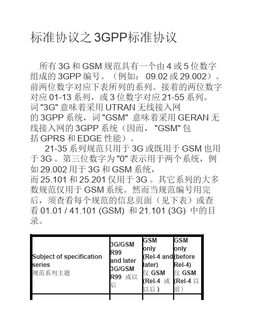
标准协议之3GPP标准协议所有3G和GSM规范具有一个由4或5位数字组成的3GPP编号。
(例如:09.02或29.002)。
前两位数字对应下表所列的系列。
接着的两位数字对应01-13系列,或3位数字对应21-55系列。
词"3G"意味着采用UTRAN无线接入网的3GPP系统,词"GSM" 意味着采用GERAN无线接入网的3GPP系统(因而,"GSM"包括GPRS和EDGE性能)。
21-35系列规范只用于3G或既用于GSM也用于3G。
第三位数字为"0"表示用于两个系统,例如29.002用于3G和GSM系统,而25.101和25.201仅用于3G。
其它系列的大多数规范仅用于GSM系统。
然而当规范编号用完后,须查看每个规范的信息页面(见下表)或查看01.01 / 41.101 (GSM) 和21.101 (3G) 中的目录。
Q=可选的子部分编号-1或2位数字,如果有V=版本号,无分隔点-3位数字例如:21900-320.zip 是3GPP TR 21.900 版本3.2.00408-6g0.zip 是3GPP TS 04.08 版本6.16.032111-4-410 是3GPP TS 32.111 部分4 版本4.1.0 29998-04-1-100 是3GPP TS 29.998 部分4 子部分1 版本----------------------------------------------------------------------------------------------------------------好好研究下这个网站/specification-numbering就明白了每一个小类后面都有说明的----------------------------------------------------------------------------------------------------------------mark。
3gpp协议导读
3gpp协议导读3GPP协议导读。
3GPP(第三代合作伙伴计划)是一个国际标准化组织,致力于制定全球移动通信系统的技术规范。
它的成员包括全球各地的电信运营商、设备制造商、技术提供商和其他利益相关者。
3GPP协议是由这些成员共同制定的,它规定了移动通信系统的各种技术规范和协议。
首先,我们来了解一下3GPP协议的组成。
3GPP协议由多个技术规范组成,其中包括Radio Access Network(RAN,无线接入网络)、Core Network(CN,核心网络)和Services(业务)等部分。
RAN包括了移动通信系统中的基站和无线接入网,而CN则包括了核心网和传输网。
Services部分则涵盖了各种移动通信业务,如语音通信、短信、数据传输等。
这些技术规范和协议共同构成了3GPP协议的框架。
在3GPP协议中,最重要的部分之一就是无线接入技术。
目前,3GPP协议中使用的无线接入技术包括了GSM、UMTS和LTE等。
GSM是全球移动通信系统的第一个数字无线通信技术,它为后来的移动通信技术奠定了基础。
UMTS则是3GPP协议中的第三代移动通信技术,它提供了更高的数据传输速率和更丰富的业务功能。
而LTE则是4G移动通信技术,它进一步提高了数据传输速率和网络容量,为移动宽带通信提供了更好的支持。
此外,在3GPP协议中,核心网技术也是至关重要的。
核心网是移动通信系统的中枢部分,它负责处理用户数据、信令和业务控制等功能。
在3GPP协议中,核心网技术包括了移动交换中心(MSC)、业务支持系统(BSS)、家庭位置寻呼(HPLMN)等。
这些技术规范和协议为移动通信系统的正常运行提供了基础支持。
除了无线接入技术和核心网技术,3GPP协议中还包括了各种业务规范和协议。
这些业务规范和协议涵盖了移动通信系统中的各种业务需求,如语音通信、短信、数据传输、位置服务等。
它们为移动通信系统的各种业务提供了技术支持和规范要求。
总的来说,3GPP协议是移动通信系统的技术规范和协议,它由全球各地的电信运营商、设备制造商、技术提供商和其他利益相关者共同制定。
36系列各版本协议说明
规范撤销
TR 36.800 TR 36.801 TR 36.803 TR 36.804 TR 36.805 TR 36.806 TR 36.807 TR 36.808 TR 36.809 TR 36.810 TR 36.811
规范撤销 规范撤销 规范撤销
LTE 中的射频(RF)模式匹配定位方法
UTRA 和 E-UTRA,欧洲的在 800 MHz 下的 UMTS/ LTE E-UTRA, 为移动卫星服务 (MSS) 的辅助地面组件 (ATC) 添加 2 GHz 频段 LTE 频分复用(FDD)(Band 23) E-UTRA,美国工作项目技术报告中的 LTE TDD 2600MHz E-UTRA,LTE L 波段技术报告 E-UTRA,对于 E-UTRA 物理层方面的进一步进展 E-UTRA,RAN WG4 下 LTE-Advanced 的可行性研究 E-UTRA,对设备共存信令和程序干扰避免的研究 E-UTRA,上行链路多天线传输;基站(BS)无线电发射和接收 扩展 1900MHz
E-UTRA,位于频带 38 的 LTE-Advanced 带间连续载波聚合(CA) E-UTRA,位于频带 39 的 LTE-Advanced 带间连续载波聚合(CA) E-UTRA,位于频带 41 的 LTE-Advanced 带间连续载波聚合(CA) E-UTRA,位于频带 42 的 LTE-Advanced 带间连续载波聚合(CA) E-UTRA,位于频带 2 的 LTE-Advanced 带间非连续载波聚合(CA) E-UTRA,位于频带 3 的 LTE-Advanced 带间非连续载波聚合(CA) E-UTRA,位于频带 4 的 LTE-Advanced 带间非连续载波聚合(CA) E-UTRA,位于频带 7 的 LTE-Advanced 带间非连续载波聚合(CA) E-UTRA,位于频带 23 的 LTE-Advanced 带间非连续载波聚合(CA) E-UTRA,位于频带 25 的 LTE-Advanced 带间非连续载波聚合(CA) E-UTRA,位于频带 42 的 LTE-Advanced 带间非连续载波聚合(CA) E-UTRA,对于 2 个上行链路(2UL)的 LTE-Advanced 带间非连续 载波聚合(CA) ;架构 E-UTRA,对于 2 个上行链路(2UL)的位于频带 4 的 LTE-Advanced 带间非连续载波聚合(CA) E-UTRA, 对于 3 个下行链路 (3DL) 的位于频带 40 的 LTE-Advanced 带间非连续载波聚合(CA) E-UTRA, 对于 3 个下行链路 (3DL) 的位于频带 41 的 LTE-Advanced 带间非连续载波聚合(CA) E-UTRA, 对于 3 个下行链路 (3DL) 的位于频带 42 的 LTE-Advanced 带间非连续载波聚合(CA) E-UTRA, 对于 3 个下行链路 (3DL) 的位于频带 41 的 LTE-Advanced 带间非连续载波聚合(CA) E-UTRA, 对于 3 个下行链路 (3DL) 的位于频带 42 的 LTE-Advanced 带间非连续载波聚合(CA) E-UTRA, 对于 4 个下行链路 (4DL) 的位于频带 42 的 LTE-Advanced 带间非连续载波聚合(CA) E-UTRA, 对于 4 个下行链路 (4DL) 的位于频带 41 的 LTE-Advanced 带间非连续载波聚合(CA) 位于频带 3 的 LTE-Advanced 带间连续载波聚合(CA) 位于频带 1 的带间连续载波聚合(CA) E-UTRA,移动中继的研究
916013GPPTS36.523-1V9.3.0(2010-12)
Table 10.5.1.3.3-3: Message ACTIVATE DEDICATED EPS BEARER CONTEXT REQUEST (step 3, Table10.5.1.3.2-1)Derivation Path: TS 36.508 Table 4.7.3-3Information Element Value/remark Comment Condition EPS bearer identity 7Procedure transaction identity 0 No proceduretransactionidentity assignedLinked EPS bearer identity 6EPS QoS According to referencededicated EPS bearercontext #2 - see [18] SS defines an additional dedicated EPS QoSTFT According to referencededicated EPS bearercontext #2 - see [18]Table 10.5.1.3.3-4: Message ACTIVATE DEFAULT EPS BEARER CONTEXT ACCEPT (step 4, Table10.5.1.3.2-1)Derivation Path: TS 36.508 Table 4.7.3-4Information Element Value/remark Comment Condition EPS bearer identity 6Procedure transaction identity 0 No proceduretransactionidentity assignedTable 10.5.1.3.3-5: Message ACTIVATE DEDICATED EPS BEARER CONTEXT ACCEPT (step 6, Table10.5.1.3.2-2)Derivation Path: TS 36.508 Table 4.7.3-1Information Element Value/remark Comment Condition EPS bearer identity 7Procedure transaction identity 0 No proceduretransactionidentity assigned10.5.2 Void10.5.3 UE requested PDN connectivity not accepted10.5.3.1 Test Purpose (TP)(1)with { the UE has sent a PDN CONNECTIVITY REQUEST message to an additional PDN }ensure that {when { the UE receives an PDN CONNECTIVITY REJECT message with PTI matching the PDN CONNECTIVITY REQUEST message and including a ESM cause value }then { the UE enters the state PROCEDURE TRANSACTION INACTIVE }}10.5.3.2 Conformance requirementsReferences: The conformance requirements covered in the present TC are specified in: TS 24.301, clauses 6.2.2,6.4.1.3, 6.4.2.3 and 6.5.1.2.[TS 24.301, clause 6.2.2]The UE shall set the PDN type IE in the PDN CONNECTIVITY REQUEST message, based on its IP stack configuration as follows:a) A UE, which is IPv6 and IPv4 capable and- has not been allocated an IP address for this APN, shall set the PDN type IE to IPv4v6.- has been allocated an IPv4 address for this APN and received the ESM cause #52 "single address bearers only allowed", and is requesting an IPv6 address, shall set the PDN type IE to IPv6.- has been allocated an IPv6 address for this APN and received the ESM cause #52 "single address bearers only allowed", and is requesting an IPv4 address, shall set the PDN type IE to IPv4.b) A UE, which is only IPv4 capable, shall set the PDN type IE to IPv4.c) A UE, which is only IPv6 capable, shall set the PDN type IE to IPv6.d) When the IP version capability of the UE is unknown in the UE (as in the case when the MT and TE areseparated and the capability of the TE is not known in the MT), the UE shall set the PDN type IE to IPv4v6. ...[TS 24.301, clause 6.5.1.2]...In order to request connectivity to an additional PDN, the UE shall send a PDN CONNECTIVITY REQUEST message including a requested APN to the MME, start timer T3482 and enter the state PROCEDURE TRANSACTION PENDING (see example in figure 6.5.1.2.1). In the PDN type information element the UE shall indicate the IP version capability of the IP stack associated with the UE as specified in subclause 6.4.1The UE shall set the request type to "initial request" when the UE is establishing connectivity to a PDN for the first time, i.e. when it is an initial attach to that PDN. The UE shall set the request type to "handover" when the connectivity to a PDN is established upon handover from a non-3GPP access network and the UE was connected to that PDN before the handover to the 3GPP access network....[TS 24.301, clause 6.5.1.4]...Upon receipt of the PDN CONNECTIVITY REJECT message, the UE shall stop timer T3482 and enter the state PROCEDURE TRANSACTION INACTIVE.The PDN CONNECTIVITY REJECT message contains an ESM cause IE that typically indicates one of the following ESM cause values:#8: operator determined barring;#26: insufficient resources;#27: missing or unknown APN;#28: unknown PDN type;#29: user authentication failed;#30: request rejected by Serving GW or PDN GW;#31: request rejected, unspecified;#32: service option not supported;#33: requested service option not subscribed;#34: service option temporarily out of order;#35: PTI already in use;#38: network failure;#50: PDN type IPv4 only allowed;#51: PDN type IPv6 only allowed;#53: ESM information not received;#54: PDN connection does not exist;#55: multiple PDN connections for a given APN not allowed;#95 – 111: protocol errors;#112: APN restriction value incompatible with active EPS bearer context.10.5.3.3 Test description10.5.3.3.1 Pre-test conditionsSystem Simulator:- Cell A.UE:None.Preamble:- The UE is in state Registered, Idle mode (state 2) according to [18] (1 default EPS bearer context is active).10.5.3.3.2 Test procedure sequenceTable 10.5.3.3.2-1: Main behaviourSt Procedure Message Sequence TP VerdictU - S Message1 Cause the UE to request connectivity to anadditional PDN (see Note)- - - -1A The UE transmits a SERVICE REQUEST --> SERVICE REQUEST - -1B The SS establishes SRB2 and DRBassociated with the default EPS bearer contextactivated during the preamble (a first PDNobtained during the attach procedure).- - - -2 The UE transmits a PDN CONNECTIVITYREQUEST message as specified to request anadditional PDN.--> PDN CONNECTIVITY REQUEST - -3 The SS transmits a PDN CONNECTIVITYREJECT message.<-- PDN CONNECTIVITY REJECT - -4 Void - - - -5 Void - - - -6 The SS releases the RRC connection. - - - -7 Cause the UE to request connectivity to anadditional PDN (see Note)- - - -8 The UE transmits a SERVICE REQUESTmessage.--> SERVICE REQUEST - -9 The SS establishes a DRB associated with thedefault EPS bearer context activated duringthe preamble.- - - -9A Check: Does the UE transmit a PDNCONNECTIVITY REQUEST as specified torequest an additional PDN?--> PDN CONNECTIVITY REQUEST 1 P9B The SS transmits an ACTIVATE DEFAULT EPS BEARER CONTEXT REQUESTmessage with IE EPS Bearer Identity set tonew EPS bearer context.Note:ACTIVATE DEFAULT EPS BEARERCONTEXT REQUEST is included indedicatedInfoNASList ofRRCConnectionReconfiguration message. <-- ACTIVATE DEFAULT EPSBEARER CONTEXT REQUEST- -10 Check: Does the UE transmit an ACTIVATEDEFAULT EPS BEARER CONTEXT ACCEPTmessage for the additional default EPSbearer? --> ACTIVATE DEFAULT EPSBEARER CONTEXT ACCEPT1 PNote: The trigger in step 1 and the RRC messages in steps 1A to 2 and in steps 8 to 10 are the same as in the generic procedure in 36.508 clause 6.4.3.2. The request of connectivity to an additional PDN may be performed by MMI or AT command.10.5.3.3.3 Specific message contentsTable 10.5.3.3.3-1: Message PDN CONNECTIVITY REQUEST (step 2, table 10.5.3.3.2-1) Derivation Path: TS 36.508 Table 4.7.3-20Information Element Value/remark Comment Condition EPS bearer identity 0000 No EPS beareridentity assignedProcedure transaction identity PTI-1 UE assigns aparticular PTI notyet used between1 and 254ESM information transfer flag Not present This IE is onlyactivable duringan attachprocedure.Access point name APN-1(New PDN name) The requestedPDN is differentfrom default PDNTable 10.5.3.3.3-2: Message PDN CONNECTIVITY REJECT (step 3, table 10.5.3.3.2-1) Derivation Path: TS 36.508 Table 4.7.3-19Information Element Value/remark Comment Condition EPS bearer identity 0000 No EPS beareridentity assignedProcedure transaction identity PTI-1 The SS indicatesthe same valuelike received inthe PDNCONNECTIVITYREQUESTESM cause 01101111 “Protocol error,unspecified”Protocol configuration options Not presentTable 10.5.3.3.3-3: VoidTable 10.5.3.3.3-4: Message PDN CONNECTIVITY REQUEST (step 9A, table 10.5.3.3.2-1) Derivation Path: TS 36.508 Table 4.7.3-20Information Element Value/remark Comment Condition EPS bearer identity 0000 No EPS beareridentity assignedProcedure transaction identity PTI-2 UE assigns aparticular PTI notyet used between1 and 254 (maybe identical toPTI-1)ESM information transfer flag Not present This IE is onlyactivable duringan attachprocedure.Access point name APN-2 (New PDN name) The requestedPDN is differentfrom default PDN(may be identicalto APN-1)Table 10.5.3.3.3-5: Message ACTIVATE DEFAULT EPS BEARER CONTEXT REQUEST (step 9B, table10.5.3.3.2-1)Derivation Path: TS 36.508 Table 4.7.3-6 and table 4.6.1-8 with condition AM-DRB-ADD(2)Information Element Value/remark Comment Condition EPS bearer identity 6Procedure transaction identity PTI-2 SS re-uses theparticular PTIdefined by UE forthis presentadditional PDNconnectivityrequestprocedure.Access point name APN-2 SS re-uses theparticular APNdefined by UE forthis presentadditional PDNconnectivityrequest procedureTable 10.5.3.3.3-6: Message ACTIVATE DEFAULT EPS BEARER CONTEXT ACCEPT (step 10, table10.5.3.3.2-1)Derivation path: 36.508 table 4.7.3-1Information Element Value/Remark Comment Condition EPS bearer identity 6 Same value as inACTIVATEDEFAULT EPSBEARERCONTEXTREQUESTProcedure transaction identity 0 "No proceduretransactionidentity assigned"10.6 UE requested PDN disconnect10.6.1 UE requested PDN disconnect procedure accepted by the network 10.6.1.1 Test Purpose (TP)(1)with { UE is in BEARER CONTEXT ACTIVE STATE state }ensure that {when { UE is triggered to disconnect from a PDN }then { UE sends a PDN DISCONNECT REQUEST message including the default EPS bearer identity associated with this PDN }}(2)with { UE is in PROCEDURE TRANSACTION PENDING state }ensure that {when { UE receives a DEACTIVATE EPS BEARER CONTEXT REQUEST message with any valid ESM cause } then { UE deactivates the default EPS bearer context for this PDN connection between the UE and the SS }}10.6.1.2 Conformance requirementsReferences: The conformance requirements covered in the present TC are specified in: TS 24.301, clauses 6.5.2.2, and 6.5.2.4.。
3gpp协议中文目录
3gpp协议中文目录篇一:3GPP 24008中文版协议1. 简述该文档描述了第三代移动通信系统和数字小区通信系统内用在无线接口的核心网协议流程。
主要描述了无线接口上的流程(参考接口Um或Uu,参考跑3GPP 24.002或3GPP 23.002)比如呼叫控制CC, 移动性管理MM,和会话管理SM。
文中每当提及further study或FS或FFS的地方表示本文不会对相应的内容作标准阐述。
这些流程都是按照无线接口的控制信道上交换的信令定义的。
控制信道在3GPP 44.003和3GPP 25.301中描述。
该协议的功能性描述和流程,以及其他层和实体间的交互将在3GPP 24.007中描述。
1.3 层3流程的结构可以用“积木”法来描述层3的流程。
基础的积木是三个子层的协议控制实体提供的“基本流程”,这些子层是无线资源管理RRM,移动性管理MM和连接管理CM。
11.5 在A/Gb模式下逻辑信道的使用逻辑信道在3GPP 45.002中定义。
下述的这些控制信道都是承载信令信息或指定类型的用户分组数据:1) 广播控制信道BCCH:下行,用来广播小区独有信息2) 同步信道SCH:下行,用来广播同步信息和BSS标识信息3) 寻呼信道PCH:下行,用来发送寻呼给MS4) 随机接入信道RACH:上行,用来请求一条专用控制信道DCCH5) 接入允许信道AGCH:下行,用来分配一条专用控制信道DCCH6) 独立专用控制信道SDCCH:双向7) 快速辅助控制信道FACCH:双向,和一条业务信道TCH关联8) 慢速辅助控制信道SACCH:双向,和一条SDCCH或者TCH关联9) 小区广播信道CBCH:下行,用作非点对点短消息传输10) 指示信道NCH:下行,用来通知用户VBS呼叫或VGCS呼叫信令层2定义了两个服务接入点,以SAPI划分(详见3GPP 44.006)21) SAPI0:支持包括用户消息的信令信息的传输2) SAPI3:支持用户短消息的传输层3根据每条消息进行SAP的选择,以及逻辑控制信道的选择,L2操作模式(确认模式AM,非确认模式UM或随机接入)的选择。
- 1、下载文档前请自行甄别文档内容的完整性,平台不提供额外的编辑、内容补充、找答案等附加服务。
- 2、"仅部分预览"的文档,不可在线预览部分如存在完整性等问题,可反馈申请退款(可完整预览的文档不适用该条件!)。
- 3、如文档侵犯您的权益,请联系客服反馈,我们会尽快为您处理(人工客服工作时间:9:00-18:30)。
3GPP TR 36.843 V12.0.1 (2014-03)Technical Report3rd Generation Partnership Project;Technical Specification Group Radio Access Network;Study on LTE Device to Device Proximity Services;Radio Aspects(Release 12)The present document has been developed within the 3rd Generation Partnership Project (3GPP TM) and may be further elaborated for the purposes of 3GPP. The present document has not been subject to any approval process by the 3GPP Organizational Partners and shall not be implemented.This Report is provided for future development work within 3GPP only. The Organizational Partners accept no liability for any use of this Specification. Specifications and Reports for implementation of the 3GPP TM system should be obtained via the 3GPP Organizational Partners' Publications Offices.KeywordsLTE, Device-to-Device3GPPPostal address3GPP support office address650 Route des Lucioles - Sophia AntipolisValbonne - FRANCETel.: +33 4 92 94 42 00 Fax: +33 4 93 65 47 16InternetCopyright NotificationNo part may be reproduced except as authorized by written permission.The copyright and the foregoing restriction extend to reproduction in all media.© 2014, 3GPP Organizational Partners (ARIB, ATIS, CCSA, ETSI, TTA, TTC).All rights reserved.UMTS™ is a Trade Mark of ETSI registered for the benefit of its members3GPP™ is a Trade Mark of ETSI registered for the benefit of its Members and of the 3GPP Organizational Partners LTE™ is a Trade Mark of ETSI registered for the benefit of its Members and of the 3GPP Organizational Partners GSM® and the GSM logo are registered and owned by the GSM AssociationContentsForeword (5)1Scope (6)2References (7)3Definitions and abbreviations (8)3.1Definitions (8)3.2Abbreviations (8)4Public Safety Use Cases and Scenarios (9)5Requirements (10)6General design assumptions (10)6.1Multiple access scheme (10)6.1.1UE transmitter performance (11)6.1.2UE receiver performance (11)6.2Multiplexing of signals (11)6.3Signal design details (12)7Synchronization (13)7.1Signal design (13)7.2Procedure (13)7.2.1Transmission of D2DSS (13)7.2.2Selection of timing reference D2D Synchronization Source (14)7.2.3Transmission timing offset (14)8Discovery (16)8.1Types of Discovery (16)8.2Physical layer design (16)8.2.1Signal design (16)8.2.2Resource allocation (17)8.2.3Transmission timing offset (18)8.3Upper layer aspects (19)8.3.1General (19)8.3.2Radio protocol architecture (20)8.3.3Radio resource management aspect (21)8.3.3.1Protocol states (21)8.3.3.2Radio resource allocation (21)8.3.3.3Procedure (21)9Communication (22)9.1Physical layer design (22)9.1.1Signal design (22)9.1.2Resource allocation (22)9.2Upper layer aspects (23)9.2.1General (23)9.2.2Radio protocol architecture (24)9.2.2.1Control-plane (24)9.2.2.2User-plane (24)9.2.3 Radio resource management aspect (24)9.2.3.1Protocol states (24)9.2.3.2Radio resource allocation (24)9.2.3.3Procedure (25)10Evaluation results for D2D (26)10.1Evaluation results for discovery (26)10.2Evaluation results for communication (29)11Conclusion (32)Annex A: Simulation model (33)A.1Link simulation Scenarios (33)A.2System simulation Scenarios (33)A.2.1System simulation assumptions (33)A.2.1.1Reference system deployments (33)A.2.1.1.1Dropping and Association for Unicast (37)A.2.1.1.2Dropping and Association for Groupcast (38)A.2.1.1.3Dropping and Association for Broadcast (38)A.2.1.2Channel models (39)A.2.1.2.1Doppler modelling (41)A.2.1.2.1.1System level (41)A.2.1.2.1.2Link level (41)A.2.1.3Traffic models (43)A.2.1.4Performance evaluation metrics (43)A.2.1.4.1Metrics for discovery (43)A.2.1.4.2Metrics for communication (44)A.2.1.5In-band emissions model (45)A.2.1.6Power consumption model (46)A.2.2System level simulator calibration (46)A.3Detailed simulation results (46)A.4Public Safety ProSe Communication Use Cases (47)A.4.1Typical Public Safety Use Cases and Scenarios of ProSe Communication (47)A.4.1.1General Description of Public Safety ProSe Communication Scenarios (47)A.4.1.2Typical Use Cases of Public Safety ProSe Communication (48)A.4.2Typical performance values and E-UTRAN characteristics for Public Safety of ProSe Communication (49)A.4.2.1Basic operations (49)A.4.2.2Coverage (49)A.4.2.3Applications (49)A.4.2.4System Aspects (49)Annex B: Change history (50)ForewordThis Technical Report has been produced by the 3rd Generation Partnership Project (3GPP).The contents of the present document are subject to continuing work within the TSG and may change following formal TSG approval. Should the TSG modify the contents of the present document, it will be re-released by the TSG with an identifying change of release date and an increase in version number as follows:Version x.y.zwhere:x the first digit:1 presented to TSG for information;2 presented to TSG for approval;3 or greater indicates TSG approved document under change control.y the second digit is incremented for all changes of substance, i.e. technical enhancements, corrections, updates, etc.z the third digit is incremented when editorial only changes have been incorporated in the document.1 ScopeThe present document contains the result of the Device to Device (D2D) study item.The Feasibility Study on Proximity-based Services (FS_ProSe, TR 22.803 [2]) has identified services that could be provided by the 3GPP system based on UEs being in proximity to each other. The identified areas include services related to commercial services and Public Safety that would be of interest to operators and users.The objectives of this feasibility study are to evaluate LTE Device to Device proximity services, as follows:In particular:1.Define an evaluation methodology and channel models for LTE device to device proximity services, includingscenarios to compare different technical options to realize proximal device discovery and communication,appropriate performance metrics, and performance targets (e.g. range, throughput, number of UEs supported).[RAN1]2.Identify physical layer options and enhancements to incorporate in LTE the ability for devices within networkcoverage: [RAN1]:- to discover each other in proximity directly in a power-efficient manner.- to communicate directly, including enhancements to LTE interference management and scheduling that allow the LTE network to enable, manage, and continuously control all direct, over the air, device to devicecommunications.3.Identify and evaluate options, solutions and enhancements to the LTE RAN protocols within network coverage[RAN2 primary, RAN3 secondary]:- to enable proximal device discovery among devices under continuous network management and control, - to enable direct communication connection establishment between devices under continuous network management and control,- to allow service continuity to/from the macro network4.Consider terminal and spectrum specific aspects, e.g. battery impact and requirements deriving from direct device todevice discovery and communication [RAN4].5.Evaluate, for non public safety use cases, the gains obtained by LTE device to device direct discovery with respectto existing device to device mechanisms (e.g. WiFi Direct, Bluetooth), and existing location techniques forproximal device discovery (e.g. in terms of power consumption, and signaling overhead) [RAN1, RAN2].6.The possible impacts on existing operator services (e.g. voice calls) and operator resources should be investigated[RAN1].7.For the purposes of addressing public safety requirements, identify and study the additional enhancements andcontrol mechanisms required to realize discovery and communication outside network coverage [RAN1, RAN2]. The identified options/enhancements should reuse the features of LTE as much as possible.The study will cover:- Single and multi-operator scenarios, including the spectrum sharing case where a carrier is shared by multiple operators (subject to regional regulation and operator policy)- LTE FDD and LTE TDD operationsIn this study item, the study of direct communication shall address at least public safety requirements and use cases..It is assumed that aspects related to service authorization, system level architecture, security, and lawful interception are covered in the 3GPP TSG SA Working Groups.2 ReferencesThe following documents contain provisions which, through reference in this text, constitute provisions of the present document.- References are either specific (identified by date of publication, edition number, version number, etc.) or non-specific.- For a specific reference, subsequent revisions do not apply.- For a non-specific reference, the latest version applies. In the case of a reference to a 3GPP document (includinga GSM document), a non-specific reference implicitly refers to the latest version of that document in the sameRelease as the present document.[1] 3GPP TR 21.905: "Vocabulary for 3GPP Specifications".[2] 3GPP TR 22.803: "Feasibility study for Proximity Services (ProSe)".[3] 3GPP TR 36.814: "Evolved Universal Terrestrial Radio Access (E-UTRA); Furtheradvancements for E-UTRA physical layer aspects".[4] R4-092042, "Simulation assumptions and parameters for FDD HeNB RF requirements", Alcatel-Lucent, picoChip Designs, Vodafone.[5] 3GPP TS 36.101: "Evolved Universal Terrestrial Radio Access (E-UTRA); User Equipment (UE)radio transmission and reception".[6] WINNER II Channel Models, D1.1.2 V1.2. , available at/files/1050/documents/winner2%20-%20final%20report.pdf[7] D5.3: WINNER+ Final Channel Models, available at http://projects.celtic-/winner%2B/WINNER+%20Deliverables/D5.3_v1.0.pdf.[8] Draft new Report ITU-R M.[IMT.EVAL] "Guidelines for evaluation of radio interfacetechnologies for IMT-Advanced", Document 5/69-E.[9] R1-132341: "Channel modelling for D2D", NEC Group.[10] 3GPP TS 22.278: "Service requirements for the Evolved Packet System (EPS)".[11] R1-133186: "Typical Public Safety Use Cases, Performance Values, and E-UTRANCharacteristics for D2D ProSe Group Communication", U.S. Department of Commerce[12] NPSTG Communications Report "Public Safety Broadband Push-to-Talk over Long TermEvolution Requirements", 7/18/2013.[13] 3GPP TS 36.211: "Evolved Universal Terrestrial Radio Access (E-UTRA); Physical channels andmodulation".[14] RP-13177, "Agreements from TSG RAN on work on Public Safety related use cases in Release12", Vodafone, US Department of Commerce, UK Home Office, Motorola Solutions, GeneralDynamics Broadband UK, Telefonica, Ericsson, NSN, Alcatel-Lucent.[15] M.1579-1, "Global circulation of IMT-2000 terrestrial terminals".[16] 3GPP TS 36.212: "Evolved Universal Terrestrial Radio Access (E-UTRA); Multiplexing andchannel coding".3 Definitions and abbreviations3.1 DefinitionsFor the purposes of the present document, the terms and definitions given in TR 21.905 [1] and the following apply.A term defined in the present document takes precedence over the definition of the same term, if any, in TR 21.905 [1]. D2D Synchronization Source: A node that at least transmits a D2D synchronization signal.D2D Synchronization Signal: A signal from which a UE can obtain timing and frequency synchronization.3.2 AbbreviationsFor the purposes of the present document, the abbreviations given in TR 21.905 [1] and the following apply.An abbreviation defined in the present document takes precedence over the definition of the same abbreviation, if any, in TR 21.905 [1].D2D Device to DeviceD2DSS D2D Synchronization SignalPD2DSCH Physical D2D Synchronization ChannelPD2DSS Primary D2D Synchronization SignalProSe Proximity based ServicesPS Public SafetySD2DSS Secondary D2D Synchronization Signal4 Public Safety Use Cases and ScenariosThe following use cases are relevant for PS (Public Safety) ProSe communication.Little or no coverageGuaranteed communications through the network cannot be achieved either because of attenuation due to the local environment, the mobility of the users, or a simple lack of coverage. In these situations the priority is to maintain communications with those at the incident, e.g., in buildings, on trains, between vehicles, in rural environments, underground.Fall BackUsed when there has been a complete network failure in an area that would typically have coverage, e.g., Large Scale Natural Disasters, Power Cuts, Equipment Failures.Extra CapacityUsed to provide extra capacity to manage some incidents. In existing systems there are certain system constraints that limit the number of groups and group members that can operate in an area, so the ability to communicate directly can provide extra capacity. e.g. - Large Metropolitan Areas.Local Communication RequirementThis is used in scenarios where there is no need to connect back to a control room or dispatch.Solutions for PS ProSe shall support the following scenarios:Coverage- Device to device E-UTRA Communication for Public Safety ProSe-enabled UEs is needed among withinnetwork coverage UEs, outside network coverage UEs and a mixture of UEs within and outside network coverage.- Determination is needed regarding within the device to device ProSe Communication which user(s) are in device to device ProSe Communication-coverage at any given time.- Maintaining concurrent device to device ProSe Communication (off-network) and LTE connectivity is required regardless of whether UEs are within network coverage or outside network coverage. The LTE connectivity for outside network coverage UEs are provided via UE-to-Network RelaysSpectrumPS device to device ProSe discovery and communication can be operated:- on PS ProSe specific carrier;- on a carrier also used for LTE network coverage.5 RequirementsThe requirements applicable are all the ones "radio related" reported in 3GPP TS 22.278 [10].In particular, requirements given in [10] including but not necessarily limited to the following shall be accommodated: - potential large number of concurrently participating ProSe-enabled UEs;- minimization of negative impact on the ability of the operator to provide E-UTRAN services, in particular for E-UTRA radio usage, network usage and battery consumption;- continuous network control and adaptive resources allocation between ProSe and other E-UTRAN services, as long as ProSe UEs are served by E-UTRAN;- system capability of monitoring communication characteristics;- control, by Radio Access Network, of the radio resources associated with Prose E-UTRA Communication path;- capability, by an authorised Public Safety ProSe-enabled UE, of communication using both the network infrastructure and device to device Communication with Public Safety ProSe-enabled UEs not served by E-UTRAN in parallel;- proximity criteria under full operator control.- Note: examples of proximity criteria given in [10] are just non-binding examples.According to 3GPP TS 22.278 [10]:- [1:Many Communications (where "many" also includes 1 user or 0 users) is required. Optimizations to specifically support 1:1 Communications (including "private calls"), while possible as a subset of 1:ManyCommunications, should not be a focus for 3GPP Rel-12].6 General design assumptionsIt is assumed that D2D operates in uplink spectrum (in the case of FDD) or uplink sub-frames of the cell giving coverage.- Exception: in case of TDD when out-of-coverage.- Use of downlink sub-frames in the case of TDD can be studied further.The ITU-R recommendation in [15] should be taken into account when considering D2D solutions during the course of the study item.It may be beneficial for eNodeBs to signal each other over backhaul E-UTRAN interfaces (e.g. X2 interface) the resources used for D2D.Definitions of out-of-coverage (outside network coverage), edge-of-coverage and in-coverage (within network coverage) are FFS.- For example, definition of coverage areas is at least based on downlink received power.6.1 Multiple access schemeWorking assumption for further evaluation: All data carrying physical channels use SC-FDMA for D2D signalling. RAN4 evaluated relative performance of SC-FDM and OFDM for D2D signalling. The results are discussed below.6.1.1 UE transmitter performanceCubic metric (CM) and PAPR (Peak to average power ratio) (99.9%) for OFDM and SC-FDM are listed in Table 6.1.1-1.Table 6.1.1-1: CM and PAPR for SC-FDM and OFDMThe following observations are made for UE transmitter performance:- CM and PAPR (99.9%) of OFDM are significantly higher than SC-FDM, even for narrowband waveforms.- Higher CM of OFDM compared to SC-FDM results in higher EVM and IBE on average for the same PA operating point.- PA (power amplifier) de-rating (reduction in maximum output power) for OFDM- For similar non-linear performance (e.g., w.r.t. ACLR, IBE, EVM, etc.), higher CM of OFDM necessitates PA de-rating by approximately [2.5, 2.8]dB for QPSK, and [1.7, 1.9]dB for 16QAM modulation, dependingon the number of RBs allocated.- For same UE transmit emission requirements (as defined in 3GPP TS 36.101 [5] for SC-FDM based UL transmissions), higher CM of OFDM will result in an increased MPR (maximum power reduction) forOFDM, likely even for narrowband transmissions.- PA de-rating for OFDM leads to- Loss in coverage- Higher power consumption6.1.2 UE receiver performanceThe following observations are made for UE receiver performance:- Implementation margin (IM) due to receiver impairments (non-ideal filtering, non-ideal AGC, fixed point loss, etc.) can be assumed to be the same between OFDMA and SC-FDMA receiver.- When receiving a single dominant D2D signal, the ADC SQNR/EVM performance for SC-FDMA is better than OFDMA due to reduced PAPR for SC-FDM.- Demodulation complexity for SC-FDMA is expected to be only marginally higher than OFDMA.6.2 Multiplexing of signalsFrom an ind ividual UE’s perspective:- It is assumed that D2D transmission/reception does not use full duplex on a given carrier.- D2D signal reception and uplink WAN transmission do not use full duplex on a given carrier.- For multiplexing of a D2D signal and WAN signal on a given carrier:- FDM shall not be used- Time Division Multiplexing (TDM) can be used.- This includes a mechanism for handling/avoiding collisions (details FFS).6.3 Signal design detailsTime needed for transmit to receive turn-around is assumed to be 624T s. Time needed for receive to transmit turn-around is assumed to be 624T s. (Here T s is defined in Section 4 of 3GPP TS 36.211 [13].)Working assumption:From an individual UE’s perspective, in the event of a time domain conflict between upl ink WAN transmission and D2D transmission and/or reception and/or switching, UL WAN transmission is always prioritized. As a consequence the last symbol(s) of a D2D transmission can consist of a gap.- The size of the gap is FFS between ½, 1 and 2 symbols- FFS whether the size can depend on cell size- FFS whether the gap is created by puncturing or rate matching- FFS whether, and if so how, the receiver is made aware of the presence (and length if variable) of the gap - FFS in which circumstances the gap existsWorking assumption: F rom an individual UE’s perspective:- No DTX period is introduced solely to aid switching for the case when a UE switches from uplink WAN transmission to D2D reception- No DTX period is introduced solely to aid switching for the case neither when a UE switches from D2D transmission to D2D reception, nor from D2D reception to D2D transmission.Working assumption: A D2D signal can consist of either an extended cyclic prefix (512Ts long) or a normal cyclic prefix (144 Ts long).- FFS: How the length of cyclic prefix is set.7 SynchronizationA D2D Synchronization Source transmits at least a D2D synchronization signal (D2DSS).- The transmitted D2DSS may be used by a UE to obtain time and frequency synchronization.- The D2DSS transmitted by a D2D Synchronization Source which is an eNodeB shall be the Rel-8 PSS/SSS.- The structure of D2DSS transmitted by D2D Synchronization Sources other than the eNodeB is defined in Section 7.1.- Working assumption: A synchronization source has a physical layer identity known as PSSID.7.1 Signal designWorking assumption: D2D Synchronization Sources transmits a D2DSS that:- May (FFS) carry the identity and/or type of the D2D Synchronization Source(s)- Comprises of at least a Primary D2D Synchronization Signal (PD2DSS)- PD2DSS is a Zadoff Chu sequence- Length FFS- May also comprise of a Secondary D2D Synchronization Signal (SD2DSS)- SD2DSS is a M sequence- Length FFSWorking assumption: The concept of Physical D2D Synchronization Channel (PD2DSCH) transmitted by a D2D Synchronization Source should be further discussed. This is not implying that such a channel will be defined.The channel may carry information including:- Identity of Synchronization Source- Type of Synchronization Source- Resource allocation for data and/or control signaling- Data- Others (FFS)7.2 Procedure7.2.1 Transmission of D2DSSWorking assumption: Before starting to transmit D2DSS, a UE scans for D2D Synchronization Sources.- If a D2D Synchronization Source is detected, the UE may synchronize its receiver to it before it may transmit D2DSS.- UEs may transmit at least D2DSS derived from D2DSS received from a D2D Synchronization Source.- Details of under what circumstances a UE transmits D2DSS are FFS.- If a UE transmits D2DSS, the rules for determining which D2D Synchronization Source the UE uses as the timing reference for its transmissions of D2DSS are described in Section 7.2.2.- If no D2D Synchronization Source is detected, a UE may nevertheless transmit D2DSS.- A UE may reselect the D2D Synchronization Source it uses as the timing reference for its transmissions of D2DSS if the UE detects a change in the D2D Synchronization Source(s).- Detailed rules FFS7.2.2 Selection of timing reference D2D Synchronization SourceWorking assumption: If a UE transmits a D2D signal, the rules for determining which D2D Synchronization Source the UE uses as the timing reference for its transmissions of D2D signal are- D2D Synchronization Sources which are eNodeBs have a higher priority than D2D Synchronization Sources which are UEs;- D2D Synchronization Sources which are UEs in-coverage have a higher priority than D2D Synchronization Sources which are UEs out-of-coverage;- After giving priority to D2D Synchronization Sources which are eNodeBs, followed by UEs in-coverage, selection of D2D Synchronization Source is based on at least the following metrics:- Received D2DSS quality:- For example, a UE selects a D2DSS with a better received signal quality when all the other metrics are the same.- FFS whether to define the measurement for received D2DSS quality.- FFS Stratum level: A UE selects a D2DSS with a smaller stratum level when all the other metrics are the same.- FFS on further detailed D2D Synchronization Source selection criterion.- FFS on how D2D Synchronization Source type and stratum level can be carried by D2DSS/PD2DSCH.7.2.3 Transmission timing offsetIn cases when at least one D2DSS is received by a UE, which is always the case at least in-coverage: - The UE begins to transmit a D2D signal at the time instance of T1-T2.- T1 is the reception timing of the D2DSS transmitted by the D2D Synchronization Source that the UE uses as the timing reference- T2 is an offset which is positive, negative, or zero.The value of T2 can be one of the following options.- Option 1: The selected D2D Synchronization Source used as the timing reference for transmission of its D2D signal is an eNodeB (not precluding the possibility that different D2D Synchronization Sources may be used as the timing reference at different times).- In this option, the eNodeB may or may not be the serving eNodeB of the UE- Option 1.1: T2 is fixed in the specification.- Option 1.2: T2 is configurable by the network.- Option 1.3: T2 is derived from the PUSCH transmit timing associated with the cell (this option is only applicable in cases when the UE knows the PUSCH timing).- Option 2: Void- Option 3: The selected D2D Synchronization Source used as the timing reference for transmission of its D2D signal is a UE (not precluding the possibility that different D2D Synchronization Sources may be used as the timing reference at different times).- Option 3.1: T2 is fixed in the specification.- Option 3.2: T2 is obtained from the one UENOTE: The D2DSS received from a D2D Synchronization Source might in practice in some situations be comprised of SFN transmissions from multiple D2D Synchronization Sources (although, of course this isnot visible to the receiver).- Option 4: Void- Option 5: The selected D2D Synchronization Source used as the timing reference for transmission of its D2D signal is an external source, for example GNSS.For D2D discovery signal within network coverage, Options 1 and 5 are considered for further study. For D2D discovery signal outside network coverage, Options 3 and 5 are considered for further study.For D2D communication signal, Options 1, 3, and 5 are considered for further study. At least option 1.3 is supported for within network coverage.Further study is required for the transmission timing in cases when a D2DSS is not received.8 Discovery8.1 Types of DiscoveryAt least the following two types of discovery procedure are defined for the purpose of terminology definition for use in further discussions/studies.NOTE: The following definitions are intended only to aid clarity and not to limit the scope of the study:- Type 1: a discovery procedure where resources for discovery signal transmission are allocated on a non UE specific basisNOTE: Resources can be for all UEs or group of UEs.- Type 2: a discovery procedure where resources for discovery signal transmission are allocated on a per UE specific basis:- Type 2A: Resources are allocated for each specific transmission instance of discovery signals;- Type 2B: Resources are semi-persistently allocated for discovery signal transmission.NOTE: Further details of how the resources are allocated and by which entity, and of how resources for transmission are selected within the allocated resources, are not restricted by these definitions.If D2D discovery is supported, both Type 1 and Type 2 discovery can be supported subject to investigation and positive resolving of open issues described in Section 11.8.2 Physical layer designFor inter-cell discovery, synchronous and asynchronous cells deployments should both be studied. The following two options for inter-cell discovery can be considered, including their potential applicability in different scenarios: - By directly or indirectly achieving information about the other cell synchronization reference timing;- By decoding/detecting asynchronous discovery messages/signals without necessarily prior knowledge of the associated message/signal's synchronization;- The detailed solution is FFS.Working assumption: Open and Restricted discovery messages are undistinguishable at physical layer if Open and Restricted discovery MAC PDUs have the same size.For both Type 1 and Type 2 discovery UEs transmit their discovery signal and receive discovery signals from other UEs subject to half duplex constraint.8.2.1 Signal designWorking assumption:Discovery transmissions consist of a MAC PDU.- Working assumption for further evaluation: Discovery transmissions can transmit a MAC PDU of 104 bits.- It is FFS whether a UE tr ansmits a “discovery preamble” prior to transmission of a discovery MAC PDU.- Discovery preamble can differ from a D2DSS.Working assumption: A UE that transmits a discovery MAC PDU may also be a D2D Synchronisation Source (and therefore also transmit D2DSS).Working assumption: A UE transmitting a discovery MAC PDU does not necessarily need to be a D2D Synchronisation Source.。