浮动静态路由路由黑洞问题
BGP路由黑洞
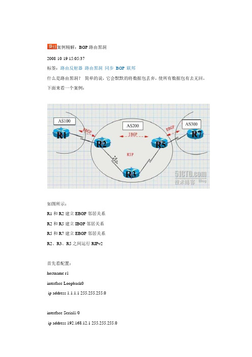
案例精解:BGP路由黑洞2008-10-19 15:05:37标签:路由反射器路由黑洞同步BGP联邦什么是路由黑洞?简单的说,它会默默的将数据包丢弃,使所有数据包有去无回,下面来看一个案例:如图所示:R1和R2建立EBGP邻居关系R2和R5建立IBGP邻居关系R5和R7建立EBGP邻居关系R2、R3、R5之间运行RIPv2首先看配置:hostname r1interface Loopback0ip address 1.1.1.1 255.255.255.0interface Serial1/0ip address 192.168.12.1 255.255.255.0serial restart-delay 0router bgp 100no synchronizationbgp router-id 1.1.1.1bgp log-neighbor-changesnetwork 1.1.1.0 mask 255.255.255.0network 192.168.12.0neighbor 2.2.2.2 remote-as 200neighbor 2.2.2.2 ebgp-multihop 255neighbor 2.2.2.2 update-source Loopback0 no auto-summary!ip route 2.2.2.0 255.255.255.0 192.168.12.2hostname r2interface Loopback0ip address 2.2.2.2 255.255.255.0!interface Serial1/0ip address 192.168.23.2 255.255.255.0serial restart-delay 0!interface Serial1/1ip address 192.168.12.2 255.255.255.0serial restart-delay 0!interface Serial1/2ip address 192.168.24.2 255.255.255.0serial restart-delay 0!router ripversion 2network 2.0.0.0network 192.168.23.0no auto-summary!router bgp 200no synchronizationbgp log-neighbor-changesnetwork 192.168.12.0network 192.168.23.0neighbor 1.1.1.1 remote-as 100neighbor 1.1.1.1 ebgp-multihop 255neighbor 1.1.1.1 update-source Loopback0 neighbor 5.5.5.5 remote-as 200neighbor 5.5.5.5 update-source Loopback0 neighbor 5.5.5.5 next-hop-selfno auto-summary!ip route 1.1.1.0 255.255.255.0 192.168.12.1hostname r3interface Loopback0ip address 3.3.3.3 255.255.255.0!interface Serial1/0ip address 192.168.35.3 255.255.255.0serial restart-delay 0!interface Serial1/1ip address 192.168.23.3 255.255.255.0 serial restart-delay 0router ripversion 2network 3.0.0.0network 192.168.23.0network 192.168.35.0no auto-summaryhostname r5interface Loopback0ip address 5.5.5.5 255.255.255.0!interface FastEthernet0/0no ip addressshutdownduplex half!interface Serial1/0ip address 192.168.57.5 255.255.255.0 serial restart-delay 0!interface Serial1/1ip address 192.168.35.5 255.255.255.0 serial restart-delay 0!interface Serial1/2ip address 192.168.45.5 255.255.255.0 serial restart-delay 0!interface Serial1/3no ip addressshutdownserial restart-delay 0!router ripversion 2network 5.0.0.0network 192.168.35.0no auto-summary!router bgp 200no synchronizationbgp log-neighbor-changesbgp confederation identifier 200neighbor 3.3.3.3 remote-as 200neighbor 7.7.7.7 remote-as 300neighbor 7.7.7.7 ebgp-multihop 255neighbor 7.7.7.7 update-source Loopback0 no auto-summary!ip route 7.7.7.0 255.255.255.0 192.168.57.7interface Serial1/1ip address 192.168.57.7 255.255.255.0serial restart-delay 0!interface Serial1/2no ip addressshutdownserial restart-delay 0!interface Serial1/3no ip addressshutdownserial restart-delay 0!router bgp 300no synchronizationbgp log-neighbor-changesneighbor 5.5.5.5 remote-as 200neighbor 5.5.5.5 ebgp-multihop 255no auto-summary!ip route 5.5.5.0 255.255.255.0 192.168.57.5现在查看R1的路由表r7#sh ip routeB 1.1.1.0 [20/0] via 5.5.5.5, 00:02:54 //为节约篇幅未完整显示可见R7学到了R1的路由,从表面上看这个实验很完美,达了目的,然而这时问题出现了,作个测试,在R7上PING R1r7#ping 1.1.1.1Type escape sequence to abort.Sending 5, 0-byte ICMP Echos to 7.7.7.7, timeout:.....这究竟是怎么回事呢?原来,我们在R5上关闭了同步,这时它会将一条并没有优化的路由传送给R7,当R7要发向R1发包时,它看到R5是它的下一跳,于是将包发给R5,然后R5又查看它的路由表,发现到R1的下一跳是R2,并继续查找,发现在通过R3可以达到R2,于是它将数据送给R3,这时问题出现了,因为R3没有运行BGP,它不知道R1怎么走,于是它将数据包丢弃,从而造成路由黑洞。
BGP路由黑洞

BGP路由黑洞一、实验目标:分析路由黑洞,并给出路由黑洞的解决方法二、网络拓扑图:三、配置:R1#router ospf 1log-adjacency-changesredistribute connected metric 1000 metric-type 1 subnets 重发布直连路由到OSPF network 10.0.1.4 0.0.0.3 area 0公布该网段,在该10.0.1.4/30网段接口运行OSPF,与R3建立OSPF邻居关系,注,只是重发布不会建立OSPF邻居,必须在接口运行OSPF,建立OSPF邻居ip route 10.0.0.0 255.255.0.0 Null0ip route 10.3.0.0 255.255.0.0 Null0 静态路由汇总router bgp 65000no synchronization 关闭同步bgp log-neighbor-changesnetwork 10.0.0.0 mask 255.255.0.0 汇总路由注入BGP network 10.3.0.0 mask 255.255.0.0neighbor 10.0.0.2 remote-as 65000 AS65000邻居10.0.0.2 neighbor 10.0.0.2 update-source Loopback0neighbor 10.0.0.2 next-hop-selfneighbor 10.0.15.2 remote-as 65001 AS65001邻居10.0.15.2 no auto-summaryR2# R2配置与R1相似router ospf 1log-adjacency-changesredistribute connected metric 1000 metric-type 1 subnets network 10.0.1.8 0.0.0.3 area 0ip route 10.0.0.0 255.255.0.0 Null0ip route 10.3.0.0 255.255.0.0 Null0router bgp 65000no synchronizationbgp log-neighbor-changesnetwork 10.0.0.0 mask 255.255.0.0network 10.3.0.0 mask 255.255.0.0neighbor 10.0.0.1 remote-as 65000neighbor 10.0.0.1 update-source Loopback0neighbor 10.0.0.1 next-hop-selfneighbor 10.0.26.2 remote-as 65002no auto-summaryR3# 公布业务网段,建立OSPF邻居,实现IGP路由可达router ospf 1log-adjacency-changesnetwork 10.0.0.3 0.0.0.0 area 0network 10.0.1.0 0.0.0.3 area 0network 10.0.1.4 0.0.0.3 area 0network 10.3.3.0 0.0.0.255 area 0R4# 公布业务网段,建立OSPF邻居,实现IGP路由可达router ospf 1log-adjacency-changesnetwork 10.0.0.4 0.0.0.0 area 0network 10.0.1.0 0.0.0.3 area 0network 10.0.1.8 0.0.0.3 area 0network 10.3.4.0 0.0.0.255 area 0R5#ip route 10.5.0.0 255.255.0.0 Null0router bgp 65001no synchronization 同步关闭bgp log-neighbor-changesnetwork 10.5.0.0 mask 255.255.0.0 汇总路由注入neighbor 10.0.15.1 remote-as 65000 与R1建立邻居no auto-summaryR6# 相似R5ip route 10.6.0.0 255.255.0.0 Null0router bgp 65002no synchronizationbgp log-neighbor-changesnetwork 10.6.0.0 mask 255.255.0.0neighbor 10.0.26.1 remote-as 65000no auto-summary路由黑洞分析RT6#ping 10.5.5.1 source 10.6.6.1 不能实现连通Type escape sequence to abort.Sending 5, 100-byte ICMP Echos to 10.5.5.1, timeout is 2 seconds: Packet sent with a source address of 10.6.6.1.....Success rate is 0 percent (0/5)查看各个路由器路由表因为关闭同步,所以R5,R6能够相互学到到达对方网段的路由RT5#show ip route10.0.0.0/8 is variably subnetted, 7 subnets, 4 masksC 10.0.15.0/30 is directly connected, Serial0/0B 10.3.0.0/16 [20/0] via 10.0.15.1, 00:14:47B 10.0.0.0/16 [20/0] via 10.0.15.1, 00:14:47B 10.6.0.0/16 [20/0] via 10.0.15.1, 00:11:44 R5学到到达R6的路由,来自R1 R5查看路由表,将数据交给R1R1经过路由递归查找,数据交给R3RT1#show ip routeC 10.0.4.0/30 is directly connected, Serial0/0O E1 10.0.0.2/32 [110/1300] via 10.0.1.5, 00:25:23, Serial0/0B 10.6.0.0/16 [200/0] via 10.0.0.2, 00:11:10B 10.5.0.0/16 [20/0] via 10.0.15.2, 00:14:13RT3# R3经过查找路由表,没有对应条目,丢弃数据包从R6到R5的过程与上类似RT6#show ip route10.0.0.0/8 is variably subnetted, 7 subnets, 4 masksB 10.3.0.0/16 [20/0] via 10.0.26.1, 00:11:52B 10.0.0.0/16 [20/0] via 10.0.26.1, 00:11:52B 10.5.0.0/16 [20/0] via 10.0.26.1, 00:11:52 R6学到到达R5的路由,来自R2C 10.0.26.0/30 is directly connected, Serial0/0RT2#show ip routeO E1 10.0.0.1/32 [110/1300] via 10.0.1.9, 00:25:30, Serial0/0B 10.6.0.0/16 [20/0] via 10.0.26.2, 00:11:16B 10.5.0.0/16 [200/0] via 10.0.0.1, 00:12:06C 10.0.26.0/30 is directly connected, Serial0/1RT4#解决方法1、关闭同步,内网BGP全连接使用peer-group命令简化BGP配置RT1(config)#router bgp 65000RT1(config-router)#neighbor 65000 peer-group 创建peer-groupRT1(config-router)#neighbor 65000 remote-as 65000RT1(config-router)#neighbor 65000 update-source loopback 0RT1(config-router)#neighbor 65000 next-hop-self peer-group的BGP邻居配置RT1(config-router)#neighbor 10.0.0.3 peer-group 65000RT1(config-router)#neighbor 10.0.0.4 peer-group 65000 加入peer-groupRT2(config)#router bgp 65000 参见R1RT2(config-router)#neighbor 65000 peer-groupRT2(config-router)#neighbor 65000 remote-as 65000RT2(config-router)#neighbor 65000 update-source loopback 0RT2(config-router)#neighbor 65000 next-hop-selfRT2(config-router)#neighbor 10.0.0.3 peer-group 65000RT2(config-router)#neighbor 10.0.0.4 peer-group 65000RT3(config)#router bgp 65000 R3运行BGP,与AS65000中所有路由器建立邻居RT3(config-router)#neighbor 65000 peer-groupRT3(config-router)#neighbor 65000 remote-as 65000RT3(config-router)#neighbor 65000 next-hop-selfRT3(config-router)#neighbor 65000 update-source lo0RT3(config-router)#neighbor 10.0.0.1 peer-group 65000RT3(config-router)#neighbor 10.0.0.2 peer-group 65000RT3(config-router)#neighbor 10.0.0.4 peer-group 65000RT4(config)#router bgp 65000 R4运行BGP,与AS65000中所有路由器建立邻居RT4(config-router)#neighbor 65000 peer-groupRT4(config-router)#neighbor 65000 remote-as 65000RT4(config-router)#neighbor 65000 next-hop-selfRT4(config-router)#neighbor 65000 update-source lo0RT4(config-router)#neighbor 10.0.0.1 peer-group 65000RT4(config-router)#neighbor 10.0.0.2 peer-group 65000RT4(config-router)#neighbor 10.0.0.3 peer-group 65000查看BGP邻居表,实现BGP全连接RT1#show ip bgp summaryNeighbor V AS MsgRcvd MsgSent TblVer InQ OutQ Up/Down State/PfxRcd 10.0.0.2 4 65000 45 44 5 0 0 00:38:55 310.0.0.3 4 65000 13 15 5 0 0 00:09:13 010.0.0.4 4 65000 10 12 5 0 0 00:06:30 010.0.15.2 4 65001 46 47 5 0 0 00:41:08 1RT2#show ip bgp summaryNeighbor V AS MsgRcvd MsgSent TblVer InQ OutQ Up/Down State/PfxRcd 10.0.0.1 4 65000 45 46 5 0 0 00:39:04 310.0.0.3 4 65000 13 15 5 0 0 00:09:21 010.0.0.4 4 65000 10 12 5 0 0 00:06:16 010.0.26.2 4 65002 43 44 5 0 0 00:38:14 1RT3#show ip bgp summaryNeighbor V AS MsgRcvd MsgSent TblVer InQ OutQ Up/Down State/PfxRcd10.0.0.1 4 65000 15 13 5 0 0 00:09:28 310.0.0.2 4 65000 15 13 5 0 0 00:09:27 310.0.0.4 4 65000 10 10 5 0 0 00:06:34 0RT4#show ip bgp summaryNeighbor V AS MsgRcvd MsgSent TblVer InQ OutQ Up/Down State/PfxRcd 10.0.0.1 4 65000 12 10 7 0 0 00:06:49 310.0.0.2 4 65000 12 10 7 0 0 00:06:26 310.0.0.3 4 65000 10 10 7 0 0 00:06:38 0R3和R4学到全部的BGP路由RT3#show ip bgpNetwork Next Hop Metric LocPrf Weight Path* i10.0.0.0/16 10.0.0.2 0 100 0 i*>i 10.0.0.1 0 100 0 i* i10.3.0.0/16 10.0.0.2 0 100 0 i*>i 10.0.0.1 0 100 0 i*>i10.5.0.0/16 10.0.0.1 0 100 0 65001 i*>i10.6.0.0/16 10.0.0.2 0 100 0 65002 iRT4#show ip bgpNetwork Next Hop Metric LocPrf Weight Path*>i10.0.0.0/16 10.0.0.2 0 100 0 i* i 10.0.0.1 0 100 0 i*>i10.3.0.0/16 10.0.0.2 0 100 0 i* i 10.0.0.1 0 100 0 i*>i10.5.0.0/16 10.0.0.1 0 100 0 65001 i*>i10.6.0.0/16 10.0.0.2 0 100 0 65002 iRT3#show ip route10.0.0.0/8 is variably subnetted, 16 subnets, 4 masksO 10.0.1.8/30 [110/200] via 10.0.1.2, 00:15:55, FastEthernet1/0O E1 10.0.15.0/30 [110/1100] via 10.0.1.6, 00:15:55, Serial0/0O E1 10.0.1.12/30 [110/1100] via 10.0.1.6, 00:15:55, Serial0/0O E1 10.0.0.2/32 [110/1200] via 10.0.1.2, 00:15:55, FastEthernet1/0B 10.3.0.0/16 [200/0] via 10.0.0.1, 00:13:49C 10.0.0.3/32 is directly connected, Loopback0C 10.3.3.0/24 is directly connected, Ethernet3/0B 10.0.0.0/16 [200/0] via 10.0.0.1, 00:13:49C 10.0.1.0/30 is directly connected, FastEthernet1/0O E1 10.0.0.1/32 [110/1100] via 10.0.1.6, 00:15:55, Serial0/0B 10.6.0.0/16 [200/0] via 10.0.0.2, 00:13:49O 10.3.4.0/24 [110/110] via 10.0.1.2, 00:15:55, FastEthernet1/0O 10.0.0.4/32 [110/101] via 10.0.1.2, 00:15:56, FastEthernet1/0B 10.5.0.0/16 [200/0] via 10.0.0.1, 00:13:49C 10.0.1.4/30 is directly connected, Serial0/0O E1 10.0.26.0/30 [110/1200] via 10.0.1.2, 00:15:56, FastEthernet1/0RT4#show ip route10.0.0.0/8 is variably subnetted, 16 subnets, 4 masksC 10.0.1.8/30 is directly connected, Serial0/0O E1 10.0.15.0/30 [110/1200] via 10.0.1.1, 00:58:11, FastEthernet1/0O E1 10.0.1.12/30 [110/1100] via 10.0.1.10, 00:58:11, Serial0/0O E1 10.0.0.2/32 [110/1100] via 10.0.1.10, 00:58:11, Serial0/0B 10.3.0.0/16 [200/0] via 10.0.0.2, 00:11:59O 10.0.0.3/32 [110/101] via 10.0.1.1, 00:58:11, FastEthernet1/0O 10.3.3.0/24 [110/110] via 10.0.1.1, 00:58:11, FastEthernet1/0B 10.0.0.0/16 [200/0] via 10.0.0.2, 00:11:59C 10.0.1.0/30 is directly connected, FastEthernet1/0O E1 10.0.0.1/32 [110/1200] via 10.0.1.1, 00:58:11, FastEthernet1/0B 10.6.0.0/16 [200/0] via 10.0.0.2, 00:11:59C 10.3.4.0/24 is directly connected, Ethernet3/0C 10.0.0.4/32 is directly connected, Loopback0B 10.5.0.0/16 [200/0] via 10.0.0.1, 00:12:22O 10.0.1.4/30 [110/200] via 10.0.1.1, 00:58:11, FastEthernet1/0O E1 10.0.26.0/30 [110/1100] via 10.0.1.10, 00:58:11, Serial0/0RT5#ping 10.6.6.1 source 10.5.5.1Type escape sequence to abort.Sending 5, 100-byte ICMP Echos to 10.6.6.1, timeout is 2 seconds:Packet sent with a source address of 10.5.5.1!!!!!Success rate is 100 percent (5/5), round-trip min/avg/max = 128/190/280 msR3,R4之间不需要建立BGP邻居关系BGP全连接虽然能实现R5和R6相互访问,但是每个路由器都要与其他路由器建立BGP 邻居,加重了路由器负担2、开启同步,重发布BGP路由到IGP中RT4(config)#no router bgp 65000 还原R3,R4配置,关闭BGPRT3(config)#no router bgp 65000R1和R2上看,邻居R3,R4状态为Active,TCP建立不成功RT1#show ip bgp summaryNeighbor V AS MsgRcvd MsgSent TblVer InQ OutQ Up/Down State/PfxRcd 10.0.0.2 4 65000 54 53 5 0 0 00:47:23 310.0.0.3 4 65000 20 22 0 0 0 00:01:09 Active10.0.0.4 4 65000 18 20 0 0 0 00:00:48 Active10.0.15.2 4 65001 54 55 5 0 0 00:49:37 1RT2#show ip bgp summaryNeighbor V AS MsgRcvd MsgSent TblVer InQ OutQ Up/Down State/PfxRcd 10.0.0.1 4 65000 54 55 5 0 0 00:48:06 310.0.0.3 4 65000 20 22 0 0 0 00:01:52 Active10.0.0.4 4 65000 17 19 0 0 0 00:01:30 Active10.0.26.2 4 65002 52 53 5 0 0 00:47:16 1在R1,R2上开启同步RT1(config)#router bgp 65000RT1(config-router)#synchronizationRT2(config)#router bgp 65000RT2(config-router)#synchronizationRT1(config)#do show ip bgpNetwork Next Hop Metric LocPrf Weight Path* i10.0.0.0/16 10.0.0.2 0 100 0 i 未同步,丢弃*> 0.0.0.0 0 32768 i* i10.3.0.0/16 10.0.0.2 0 100 0 i 未同步,丢弃*> 0.0.0.0 0 32768 i*> 10.5.0.0/16 10.0.15.2 0 0 65001 i* i10.6.0.0/16 10.0.0.2 0 100 0 65002 i 丢弃未同步路由丢弃来自IBGP宣告的未达到同步的路由所以,R1不会把该路由通告给R5RT2(config)#do show ip bgpNetwork Next Hop Metric LocPrf Weight Path* i10.0.0.0/16 10.0.0.1 0 100 0 i*> 0.0.0.0 0 32768 i* i10.3.0.0/16 10.0.0.1 0 100 0 i*> 0.0.0.0 0 32768 i* i10.5.0.0/16 10.0.0.1 0 100 0 65001 i 丢弃未同步路由*> 10.6.0.0/16 10.0.26.2 0 0 65002 iR5和R6不学到相互的路由RT5#show ip bgpNetwork Next Hop Metric LocPrf Weight Path*> 10.0.0.0/16 10.0.15.1 0 0 65000 i*> 10.3.0.0/16 10.0.15.1 0 0 65000 i*> 10.5.0.0/16 0.0.0.0 0 32768 iRT6#show ip bgpNetwork Next Hop Metric LocPrf Weight Path*> 10.0.0.0/16 10.0.26.1 0 0 65000 i*> 10.3.0.0/16 10.0.26.1 0 0 65000 i*> 10.6.0.0/16 0.0.0.0 0 32768 i把BGP路由重发布到OSPF中,实现IGP路由同步RT1(config)#router ospf 1RT1(config-router)#redistribute bgp 65000 subnetsRT2(config)#router ospf 1RT2(config-router)#redistribute bgp 65000 subnetsR1与R2通过IGP路由,实现同步RT1#show ip routeO E2 10.6.0.0/16 [110/1] via 10.0.1.5, 00:05:03, Serial0/0RT2#show ip routeO E2 10.5.0.0/16 [110/1] via 10.0.1.9, 00:10:17, Serial0/0RT1#show ip bgpNetwork Next Hop Metric LocPrf Weight Path* i10.0.0.0/16 10.0.0.2 0 100 0 i*> 0.0.0.0 0 32768 i* i10.3.0.0/16 10.0.0.2 0 100 0 i*> 0.0.0.0 0 32768 i*> 10.5.0.0/16 10.0.15.2 0 0 65001 ir>i10.6.0.0/16 10.0.0.2 0 100 0 65002 iR表示该路由已经通过BGP路由学到,但是不能进入全局路由表RT2#show ip bgpNetwork Next Hop Metric LocPrf Weight Path* i10.0.0.0/16 10.0.0.1 0 100 0 i*> 0.0.0.0 0 32768 i* i10.3.0.0/16 10.0.0.1 0 100 0 i*> 0.0.0.0 0 32768 ir>i10.5.0.0/16 10.0.0.1 0 100 0 65001 i*> 10.6.0.0/16 10.0.26.2 0 0 65002 iR5,R6各自通过EBGP学到相互的路由RT5#show ip bgpNetwork Next Hop Metric LocPrf Weight Path*> 10.0.0.0/16 10.0.15.1 0 0 65000 i*> 10.3.0.0/16 10.0.15.1 0 0 65000 i*> 10.5.0.0/16 0.0.0.0 0 32768 i*> 10.6.0.0/16 10.0.15.1 0 65000 65002 iRT6#show ip bgpNetwork Next Hop Metric LocPrf Weight Path*> 10.0.0.0/16 10.0.26.1 0 0 65000 i*> 10.3.0.0/16 10.0.26.1 0 0 65000 i*> 10.5.0.0/16 10.0.26.1 0 65000 65001 i *> 10.6.0.0/16 0.0.0.0 0 32768 iRT3#show ip route10.0.0.0/8 is variably subnetted, 16 subnets, 4 masksO 10.0.1.8/30 [110/200] via 10.0.1.2, 00:19:10, FastEthernet1/0O E1 10.0.15.0/30 [110/1100] via 10.0.1.6, 00:19:10, Serial0/0O E1 10.0.1.12/30 [110/1100] via 10.0.1.6, 00:19:10, Serial0/0O E1 10.0.0.2/32 [110/1200] via 10.0.1.2, 00:19:10, FastEthernet1/0O E2 10.3.0.0/16 [110/1] via 10.0.1.6, 00:09:52, Serial0/0C 10.0.0.3/32 is directly connected, Loopback0C 10.3.3.0/24 is directly connected, Ethernet3/0O E2 10.0.0.0/16 [110/1] via 10.0.1.6, 00:09:52, Serial0/0C 10.0.1.0/30 is directly connected, FastEthernet1/0O E1 10.0.0.1/32 [110/1100] via 10.0.1.6, 00:19:10, Serial0/0O E2 10.6.0.0/16 [110/1] via 10.0.1.2, 00:09:52, FastEthernet1/0O 10.3.4.0/24 [110/110] via 10.0.1.2, 00:19:10, FastEthernet1/0O 10.0.0.4/32 [110/101] via 10.0.1.2, 00:19:10, FastEthernet1/0O E2 10.5.0.0/16 [110/1] via 10.0.1.6, 00:12:01, Serial0/0C 10.0.1.4/30 is directly connected, Serial0/0O E1 10.0.26.0/30 [110/1200] via 10.0.1.2, 00:19:10, FastEthernet1/0RT4#show ip route10.0.0.0/8 is variably subnetted, 16 subnets, 4 masksC 10.0.1.8/30 is directly connected, Serial0/0O E1 10.0.15.0/30 [110/1200] via 10.0.1.1, 00:18:53, FastEthernet1/0O E1 10.0.1.12/30 [110/1100] via 10.0.1.10, 00:18:53, Serial0/0O E1 10.0.0.2/32 [110/1100] via 10.0.1.10, 00:18:53, Serial0/0O E2 10.3.0.0/16 [110/1] via 10.0.1.10, 00:09:57, Serial0/0O 10.0.0.3/32 [110/101] via 10.0.1.1, 00:18:53, FastEthernet1/0O 10.3.3.0/24 [110/110] via 10.0.1.1, 00:18:53, FastEthernet1/0O E2 10.0.0.0/16 [110/1] via 10.0.1.10, 00:09:57, Serial0/0C 10.0.1.0/30 is directly connected, FastEthernet1/0O E1 10.0.0.1/32 [110/1200] via 10.0.1.1, 00:18:53, FastEthernet1/0O E2 10.6.0.0/16 [110/1] via 10.0.1.10, 00:09:57, Serial0/0C 10.3.4.0/24 is directly connected, Ethernet3/0C 10.0.0.4/32 is directly connected, Loopback0O E2 10.5.0.0/16 [110/1] via 10.0.1.1, 00:12:06, FastEthernet1/0O 10.0.1.4/30 [110/200] via 10.0.1.1, 00:18:53, FastEthernet1/0O E1 10.0.26.0/30 [110/1100] via 10.0.1.10, 00:18:53, Serial0/0RT6#ping 10.5.5.1 source 10.6.6.1Type escape sequence to abort.Sending 5, 100-byte ICMP Echos to 10.5.5.1, timeout is 2 seconds:Packet sent with a source address of 10.6.6.1!!!!!Success rate is 100 percent (5/5), round-trip min/avg/max = 140/184/236 ms重发布BGP路由进入IGP路由虽然能解决路由同步问题,但是因特网上路由有十几万条,该方法不可行3、路由反射器使用路由反射技术,代替BGP互连接RT1(config-router)#no synchronization 关闭同步RT2(config-router)#no synchronizationR1作路由反射器,其他路由器都是客户端RT1(config)#router bgp 65000RT1(config-router)#neighbor 10.0.0.2 route-reflector-clientRT1(config-router)#neighbor rr peer-groupRT1(config-router)#neighbor rr update-source lo0RT1(config-router)#neighbor rr remote-as 65000RT1(config-router)#neighbor rr next-hop-selfRT1(config-router)#neighbor rr route-reflector-clientRT1(config-router)#neighbor 10.0.0.3 peer-group rrRT1(config-router)#neighbor 10.0.0.4 peer-group rrRT1(config-router)#RT3(config)#router bgp 65000RT3(config-router)#neighbor 10.0.0.1 remote-as 65000RT3(config-router)#neighbor 10.0.0.1 update-source lo0RT3(config-router)#neighbor 10.0.0.1 next-hop-selfRT4(config)#router bgp 65000RT4(config-router)#neighbor 10.0.0.1 remote-as 65000RT4(config-router)#neighbor 10.0.0.1 update-source lo0RT4(config-router)#neighbor 10.0.0.1 next-hop-selfRT1#show ip bgpNetwork Next Hop Metric LocPrf Weight Path*> 10.0.0.0/16 0.0.0.0 0 32768 i* i 10.0.0.2 0 100 0 i*> 10.3.0.0/16 0.0.0.0 0 32768 i* i 10.0.0.2 0 100 0 i*> 10.5.0.0/16 10.0.15.2 0 0 65001 i*>i10.6.0.0/16 10.0.0.2 0 100 0 65002 iRT2#show ip bgpNetwork Next Hop Metric LocPrf Weight Path* i10.0.0.0/16 10.0.0.1 0 100 0 i*> 0.0.0.0 0 32768 i* i10.3.0.0/16 10.0.0.1 0 100 0 i*> 0.0.0.0 0 32768 i*>i10.5.0.0/16 10.0.0.1 0 100 0 65001 i*> 10.6.0.0/16 10.0.26.2 0 0 65002 iR1,R2关于10.6.0.0/16的下一跳指向10.0.0.2 ,因为该路由是通过路由反射得到RT3#show ip bgpNetwork Next Hop Metric LocPrf Weight Path*>i10.0.0.0/16 10.0.0.1 0 100 0 i*>i10.3.0.0/16 10.0.0.1 0 100 0 i*>i10.5.0.0/16 10.0.0.1 0 100 0 65001 i*>i10.6.0.0/16 10.0.0.2 0 100 0 65002 iRT4#show ip bgpNetwork Next Hop Metric LocPrf Weight Path*>i10.0.0.0/16 10.0.0.1 0 100 0 i*>i10.3.0.0/16 10.0.0.1 0 100 0 i*>i10.5.0.0/16 10.0.0.1 0 100 0 65001 i*>i10.6.0.0/16 10.0.0.2 0 100 0 65002 iRT5#show ip bgpNetwork Next Hop Metric LocPrf Weight Path*> 10.0.0.0/16 10.0.15.1 0 0 65000 i*> 10.3.0.0/16 10.0.15.1 0 0 65000 i*> 10.5.0.0/16 0.0.0.0 0 32768 i*> 10.6.0.0/16 10.0.15.1 0 65000 65002 iRT6#show ip bgpNetwork Next Hop Metric LocPrf Weight Path*> 10.0.0.0/16 10.0.26.1 0 0 65000 i*> 10.3.0.0/16 10.0.26.1 0 0 65000 i*> 10.5.0.0/16 10.0.26.1 0 65000 65001 i*> 10.6.0.0/16 0.0.0.0 0 32768 i四、总结:路由同步的概念,来自IBGP的BGP路由条目不会无效,并且不会发给EBGP邻居,除非该路由能通过IGP路由学到。
静态路由导致环路的问题案例-Public

静态路由导致环路的问题目录1组网介绍 ................................................................................................................................... 1-21.1 网络拓扑图 ................................................................................................................................... 1-21.2 问题描述....................................................................................................................................... 1-31.3 问题分析....................................................................................................................................... 1-41.4 定位过程....................................................................................................................................... 1-51.5 原因分析..................................................................................................................................... 1-121.6 解决办法..................................................................................................................................... 1-171 组网介绍1.1 网络拓扑图某公司总部与多个分部使用专线进行连接,具体组网拓扑及路由如上图所示,总部和分部之间每天都用大量的业务进行互访,4M专线线路带宽接近饱和。
黑洞路由原理

黑洞路由原理
黑洞路由是一种网络安全技术,旨在防止拒绝服务攻击(DDoS)。
它通过将攻击流量重定向到一个“黑洞”地址,避免其到达目标服务器。
这个“黑洞”地址实际上就是一个不存在的地址,因此攻击流量
会在被重定向后消失。
黑洞路由的实现是通过修改网络路由器的路由表来完成的。
当网
络流量到达路由器时,它会根据路由表中的信息将数据包转发到下一
个路由器或目标服务器。
为了使用黑洞路由技术,管理员可以在路由
表中添加一个虚假的IP地址来作为黑洞地址。
当接收到攻击流量后,
路由器会将其重定向到黑洞地址,从而避免攻击流量到达目标服务器。
黑洞路由技术的主要优点是方便快捷,且能够快速缓解DDoS攻
击带来的影响。
然而,它并不能完全解决DDoS攻击,因为攻击者仍然
可以通过持续增加攻击量来克服黑洞路由的限制。
此外,如果管理员
不小心将合法流量路由到黑洞地址,那么它也会对正常的网络流量造
成影响。
对于这种情况,管理员需要非常小心谨慎。
黑洞路由的原理

黑洞路由的原理黑洞路由是网络中一种特殊的路由方式,其原理是通过将特定的网络流量传送到一种虚拟的“黑洞”地址或丢弃该流量,从而实现网络治理和防御策略。
当网络中出现异常流量或攻击时,黑洞路由可以将这些流量有效地隔离和丢弃,以保护网络的正常运行。
黑洞路由的实现依赖于路由器和流量过滤技术。
当网络中某个节点或目的地出现异常流量或攻击时,网络管理员可以通过配置路由器,将这些流量导向一个虚拟的黑洞地址。
而这个黑洞地址实际上并不存在于网络中,故而该流量将被丢弃或屏蔽。
具体而言,黑洞路由的实现过程如下:1. 网络管理员检测到网络中流量异常的节点或目的地,或者发现网络遭受攻击。
2. 网络管理员在路由器上配置黑洞路由规则。
3. 配置黑洞路由规则时,可以指定需要丢弃的IP地址、子网或者具体的端口号等。
4. 当网络中有流量匹配到黑洞路由规则时,该流量将会被路由到黑洞地址。
5. 黑洞地址实际上并不存在于网络中,故而该流量将被丢弃或屏蔽。
通过上述过程,黑洞路由实现了对异常流量或攻击流量的隔离和丢弃。
它可以有效地防止网络中的攻击,降低攻击对网络的影响,并保护网络的正常运行。
黑洞路由的应用场景主要包括以下几个方面:1. 防御分布式拒绝服务攻击(DDoS):DDoS攻击常常通过大量流量淹没目标服务器,导致服务不可用。
黑洞路由可以将攻击流量导向虚拟地址,从而减轻对目标服务器的冲击。
2. 防御蠕虫病毒传播:蠕虫病毒常常通过网络扩散,黑洞路由可以将感染蠕虫的主机流量导向黑洞,从而减缓病毒传播速度。
3. 限制对特定IP或端口的攻击:当网络中某个特定的IP地址或端口受到攻击时,可以利用黑洞路由将攻击流量导向黑洞,以保护正常的网络通信。
尽管黑洞路由在保护网络安全方面有一定的作用,但也存在一些局限性:1. 误报风险:黑洞路由通过丢弃特定流量来实现防御,但若误判某些正常流量,则会导致正常通信的中断。
2. 丢包风险:对于黑洞路由过程中的流量,由于直接丢弃,可能会导致一部分合法流量的丢失,从而影响网络正常运行。
巧用黑洞路由

网络边缘设计巧用黑洞路由当今园区网组建的潮流中ospf已经成为大型企业网的首选路由协议,然而ospf本身的复杂性使其使用起来会带来很多潜在的问题。
对于一个健康的企业网来说ospf应该限定在汇聚的上行端口,如果把接入区域的网段直接network命令宣告到ospf区域中,那么接入区的网络动荡将直接影响整个网络的核心,而且从网络安全的角度来说把接入区域宣告进去更是直接将企业网的核心暴露出来,不法分子甚至可以伪造ospf报文直接对公司网络进行攻击。
因此接入区域与核心保持有效隔离的情况下把接入网段发布出去成为解决问题的关键。
ospf末梢区域可以减小本区域内的链路状态数据库,从而减小设备压力。
但是末梢区域内的动荡还是会影响到核心。
所以末梢区域并不能解决这个问题。
ospf引入黑洞路由的方式刚好可以达到预期的效果,同时黑洞路由很能防止路由环路的产生。
下面对此方法进行分析。
注释:1.路由信息传递情况1ospf引入静态黑洞路由发布到区域0 ,区域0中的路由器便能学习到到达接入的路径。
2.用户业务报文转发情况2用户直接将数据发送到网关所在地也就是汇聚层。
3汇聚根据静态默认路由发送到下一跳到达核心,核心向目的地转发。
4下行数据根据第五类lsa把数据送到汇聚网关。
5汇聚根据直连路由把数据发送到接入用户。
汇聚并不会根据此条黑洞路由转发,因为直连路由的优先级要比静态路由的高。
这样配置办公接入网段的路由震荡将不会影响到所配置的静态黑洞路由,进而也影响不到核心区域的ospf。
1具体实施方法通过ospf引入静态黑洞路由的方式,具体优化方法如下:(1)在配置一条静态黑洞路由路由子网掩码扩大要包含所有接入网段。
iproute-static 10.6.0.0 255.255.240.0 null0 配置掩码扩大是因为防止直连路由优先级大于静态使静态路由不生效的情况发生,同时黑洞路由能够防止环路。
(2)在ospf中引入次条静态路由因为配置的静态黑洞路由掩码要大所以这条静态路由会成为有效的路由。
华为路由交换由浅入深系列(二)静态路由、浮动路由、默认路由配置以及华为路由协议优先级总结

华为路由交换由浅入深系列(二)静态路由、浮动路由、默认路由配置以及华为路由协议优先级总结掌握目标一、配置设备名称与IP地址:二、配置静态路由三、配置浮动路由用于备份四、配置默认路由五、了解华为不同路由协议的优先级一、配置设备名称与IP地址:R1:<Huawei>system-viewEnter system view,return user view with Ctrl+Z.[Huawei]sysname R1[R1]interface g0/0/1[R1-GigabitEthernet0/0/1]ip address202.100.1.1255.255.255.0 quit[R1]interface g0/0/2[R1-GigabitEthernet0/0/2]ip add202.100.2.1255.255.255.0quit[R1-GigabitEthernet0/0/1]int lo0 =====创建环回接口[R1-LoopBack0]ip add1.1.1.1255.255.255.255[R1-LoopBack0]quit[R1]display current-configuration interface =====显示接口信息#interface GigabitEthernet0/0/0#interface GigabitEthernet0/0/1ip address202.100.1.1255.255.255.0#interface GigabitEthernet0/0/2ip address202.100.2.1255.255.255.0#interface NULL0#interface LoopBack0ip address1.1.1.1255.255.255.255R2:[R2]interface g0/0/1[R2-GigabitEthernet0/0/1]ip add202.100.1.2255.255.255.0 [R2-GigabitEthernet0/0/1]int g0/0/0[R2-GigabitEthernet0/0/0]ip add202.100.3.2255.255.255.0 [R2-GigabitEthernet0/0/0]int lo0[R2-LoopBack0]ip ad2.2.2.2255.255.255.255[R2-LoopBack0]quitR3:[R3]int g0/0/2[R3-GigabitEthernet0/0/2]ip add202.100.2.3255.255.255.0 [R3-GigabitEthernet0/0/2]int g0/0/0[R3-GigabitEthernet0/0/0]ip add202.100.3.3255.255.255.0 [R3-GigabitEthernet0/0/0]int lo0[R3-LoopBack0]ip add3.3.3.3255.255.255.255<R1>ping-c2202.100.1.2=====ping两个数据包PING202.100.1.2:56data bytes,press CTRL_C to breakReply from202.100.1.2:bytes=56Sequence=1ttl=255time=10ms Reply from202.100.1.2:bytes=56Sequence=2ttl=255time=1ms---202.100.1.2ping statistics---2packet(s)transmitted2packet(s)received0.00%packet lossround-trip min/avg/max=1/5/10ms<R1>ping-c2202.100.2.3PING202.100.2.3:56data bytes,press CTRL_C to breakReply from202.100.2.3:bytes=56Sequence=1ttl=255time=20ms Reply from202.100.2.3:bytes=56Sequence=2ttl=255time=10ms---202.100.2.3ping statistics---2packet(s)transmitted2packet(s)received0.00%packet lossround-trip min/avg/max=10/15/20ms<R1>display ip routing-table ====查看路由表Route Flags:R-relay,D-download to fib------------------------------------------------------------------------------Routing Tables:PublicDestinations:11 Routes:11Destination/Mask Proto Pre Cost Flags NextHop Interface1.1.1.1/32Direct0 127.0.0.0/8Direct0 0 D 127.0.0.1127.0.0.1127.0.0.1LoopBack00 D InLoopBack0InLoopBack0InLoopBack0GigabitEthernet0127.0.0.1/32Direct0 127.255.255.255/32Direct0 202.100.1.0/24Direct0 0 D0 D 127.0.0.1 0 D 202.100.1.1二、配置静态路由[R1]ip route-static 3.3.3.3 255.255.255.255 202.100.2.3 ===添加静态路由[R1]ip route-static 202.100.3.0 255.255.255.0 202.100.2.3[R1]display ip routing-table =====Static 代表静态路由,60 代表静态路由优先级Route Flags: R - relay, D - download to fib------------------------------------------------------------------------------Routing Tables: PublicDestinations : 13 Routes : 13Destination/Mask Proto Pre Cost Flags NextHop Interface1.1.1.1/32 Direct 03.3.3.3/32 Static 60<R1>ping -c 1 3.3.3.3 PING 3.3.3.3: 56 data bytes, press CTRL_C to breakReply from 3.3.3.3: bytes=56 Sequence=1 ttl=255 time=10 ms0 D 127.0.0.1 LoopBack0 0 RD 202.100.2.3 GigabitEthernet0<R1>ping -c 1 202.100.3.3PING202.100.3.3:56data bytes,press CTRL_C to breakReply from202.100.3.3:bytes=56Sequence=1ttl=255time=10ms三、配置浮动路由用于备份配置备份静态路由,当R1与R3之间链路出现故障时,可走R2。
bgp中null0路由防环机制

bgp中null0路由防环机制
BGP中的null0路由(也称为黑洞路由)是一种用于防止数据
包环路的机制。
当网络中出现问题时,例如当某个目的地不可达或链路故障时,BGP可以将流量引导到null0接口(一个虚
拟接口),从而丢弃所有传入的数据包。
使用null0路由的主要目的是防止路由环路。
当BGP路由器接收到来自其他路由器的可达性信息时,它将比较该路由的最长匹配前缀,并将该路由添加到其路由表中。
然后,该路由表将被用来决定流量的下一跳。
如果网络出现问题,某些路由可能会失效或是不可达。
在这种情况下,使用null0路由可以确保
将传入的流量直接丢弃,而不是进一步尝试转发到其他可能的路径。
使用null0路由的另一个好处是可以防止网络攻击,例如IP地
址欺骗或DDoS攻击。
通过将流量引导到null0接口,攻击者
无法使用假IP地址或过载网络的方式来攻击目标主机。
总结来说,BGP中的null0路由是一种用于防止数据包环路的
机制,它将流量引导到一个虚拟接口,以便丢弃不可达的流量。
它还可以用于防止网络攻击和保护目标主机的安全。
- 1、下载文档前请自行甄别文档内容的完整性,平台不提供额外的编辑、内容补充、找答案等附加服务。
- 2、"仅部分预览"的文档,不可在线预览部分如存在完整性等问题,可反馈申请退款(可完整预览的文档不适用该条件!)。
- 3、如文档侵犯您的权益,请联系客服反馈,我们会尽快为您处理(人工客服工作时间:9:00-18:30)。
本文深入剖析浮动静态路由路由黑洞问题产生的原因以及如何解决该问题。
拓扑图如上:
R1(config)#ip route 192.168.4.0 255.255.255.0 192.168.2.2 //默认情况下pc1去往pc2走R1-sw1-R2
R1(config)#ip route 192.168.4.0 255.255.255.0 192.168.3.2 100 //期待当主链路失效后路由走R1-sw2-R3 事实真会如此吗?
R2(config)#ip route 0.0.0.0 0.0.0.0 f1/0
正常情况下,即主链路可用时测试如下:
R1#traceroute 192.168.4.10 source 192.168.1.1
Type escape sequence to abort.
Tracing the route to 192.168.4.10
1 192.168.2.
2 68 msec 52 msec 12 msec
2 192.168.4.10 28 msec 68 msec 32 msec //如预期相同
现在我们在R2上关闭接口f1/0,会发生什么情况?路由会启用备用链路吗?
R2(config-if)#int f1/0
R2(config-if)#shutdown
查看路由器R1的路由表:show ip route
S 192.168.4.0/24 [1/0] via 192.168.2.2 //此处可知路由器并未启用备用链路
查看网络连通性:
R1#ping 192.168.4.10
Type escape sequence to abort.
Sending 5, 100-byte ICMP Echos to 192.168.4.10, timeout is 2 seconds: .....
Success rate is 0 percent (0/5) //由此出现了路由黑洞问题!
查看R1接口状态:
R1#show ip int b
Interface IP-Address OK? Method Status Protocol
FastEthernet0/0 192.168.2.1 YES manual up up
//此处为up up状态,尽管链路是up的,但是我们没有办法抵达网关(下一跳路由器地址)
分析可知,普通情况下浮动静态路由只适用于接口 up/down down/down的状态!在
R1、R2中间没有sw1的情况下,接口状态 up/down,会正常切换到备用链路---小伙伴们都
知道的,这里就不再实验证明。
就本拓扑而言,我们就无能为力使其切换到备用链路以避免黑洞问题了吗? NO!神器来了,
小伙伴们,神器来了! cisco ip sla 是工程师的首选!
继续下面的配置:
R1(config)#ip sla monitor 10
R1(config-sla-monitor)#$ type echo ipicmpecho protocol ipicmpecho 192.168.2.2
source-ip 192.168.2.1
R1(config-sla-monitor-echo)#timeout 1000
R1(config-sla-monitor-echo)#frequency 3
R1(config-sla-monitor-echo)#exit
R1(config)#ip sla monitor schedule 10 life forever start-time now
R1(config)#track 20 rtr 10 reachability // 以上的配置可以追踪track的状态,当
有ping包返回时track结果为up,否则为down。
R1#show track
Track 20
Response Time Reporter 10 reachability
Reachability is Down
4 changes, last change 00:03:43
Latest operation return code: Timeout
Tracked by:
STATIC-IP-ROUTING 0
R1(config)#no ip route 192.168.4.0 255.255.255.0 192.168.2.2 //这个命令一定要删
除!
R1(config)#ip route 192.168.4.0 255.255.255.0 192.168.2.2 track 20
//根据对象20的状态决定是否启用备用链路, track 20 表示该静态路由只有track状态为
up的时候才建立。
如果为down ,则启用第二条备用链路。
R1(config)#ip route 192.168.4.0 255.255.255.0 192.168.3.2 100
关闭R2 接口f1/0
R2(config)#int f1/0
R2(config-if)#shutdown
检查R1路由表:
S 192.168.4.0/24 [100/0] via 192.168.3.2 //注意此处变化
检查路由路径:
R1#traceroute 192.168.4.10
Type escape sequence to abort.
Tracing the route to 192.168.4.10
1 192.168.3.
2 160 msec 12 msec 116 msec
2 192.168.4.10 12 msec 64 msec 68 msec //备用链路启用成功!路由黑洞问题解决!。