金轮CS-2180,2280(说明书)
精伦电子二代证阅读器

居民身份证阅读器产品介绍精伦电子股份有限公司二○一一年一月目录1 精伦电子简介 (3)2 精伦电子身份证阅读器产品 (5)2.1 联机型居民身份证阅读器(iDR200) (5)2.1.1 描述 (5)2.1.2 iDR200的主要特点 (5)2.1.3 iDR200的主要接口说明 (6)2.1.4 iDR200的基本功能 (6)2.1.5 iDR200规格说明 (8)2.2 桌面型居民身份证阅读器(iDR320) (9)2.2.1 描述 (9)2.2.2 iDR320的主要特点 (9)2.2.3 iDR320的主要接口说明 (10)2.2.4 iDR320的基本功能 (10)2.2.5 iDR320规格说明 (12)1 精伦电子简介精伦电子股份有限公司是“武汉·中国光谷”国家级高新技术企业,成立于1994年,于2002年上市,是中国首家以全自然人作为发起人的上市公司,注册资本24,604.46万元,股票代码:600355。
现有精伦工业园位于武汉总部,占地310亩。
精伦电子现有控股及参股公司3家,研究开发机构2所,销售服务办事处与联络处遍布全国,市场拓展到海外市场。
旗下产品已通过ISO9001:2008质量体系认证、 ISO14001 :2004环境管理体系认证以及欧盟电子电气产品环保指令 RoHS 认证,另外,公司全面实施ERP企业资源管理系统。
精伦电子致力于各类电子智能终端的研发、设计与生产。
目前公司主营产品包括:电子广告媒体终端;电子伺服系统终端;二代身份证阅读终端;电子交易终端;电力终端;家庭媒体娱乐终端;导航定位终端等。
涵盖了:通讯、电力、传媒、三网融合、工业缝纫制造、公共安全等多个领域。
并提供各类产品的服务平台、系统及整体设计、运营方案。
精伦电子一直秉承自主知识产权和核心技术为基础的理念,每年投入销售利润的较大部分作为研发投入,与华中科技大学、上海浦东等地建立合作研发基地。
拥有国家人事部批准的博士后科研工作站,在嵌入式操作系统、嵌入式硬件设计、嵌入式软件设计、音频视频信号处理、智能卡应用技术、大型数据库应用设计、网络信息安全设计技术等方面形成了自主核心技术体系。
电磁稳定器产品说明书

ElettrologiaInduzione elettromagnetica1 / 2Pendolo di WaltenhofenDIMOSTRAZIONE E ANALISI DEL FUNZIONAMENTO DI UN FRENO A CORRENTE DI FOUCAULT.UE3040400 04/16 ALFBASI GENERALISe un disco di metallo si muove in un campo magnetico disomogeneo, in qualsiasi sezione del disco il flusso magnetico varia costantemente e sulla circonferenza della sezione viene indotta una tensione ad anello. Pertanto, nel disco di metallo scorrono prevalentemente correnti di Foucault elettriche. Nel campo magnetico queste vengono sottoposte a forze di Lorentz che inibiscono il movimento del disco nel loro complesso. Le correnti di Foucault vengono ridotte drasticamente se il disco di metallo viene intagliato, in modo che la corrente possa fluire da una sezione all'altra solo per vie traverse. In questo caso, il movimento del disco viene inibito solo minimamente.La comparsa e l'inibizione delle correnti di Foucault possono essere dimostrate in maniera efficace con un pendolo di Waltenhofen. Si tratta di un disco di metallo parzialmente intagliato che oscilla in un campomagnetico disomogeneo.VFig. 1: Corrente di Foucault/in un disco di metallo spostato ad una velocità v in un campo magnetico disomogeneo B 1, B 2 e con forze di Lorentz F 1 e F 2 su entrambe le diramazioni della corrente di Foucault. La forza rivolta contro il movimento è superiore alla forza in direzione di movimento.Fig. 2: Montaggio pendolo di WaltenhofenUE3040400 3B SCIENTIFIC® PHYSICS EXPERIMENT3B Scientific GmbH, Rudorffweg 8, 21031 Amburgo, Germania, © Copyright 2016 3B Scientific GmbHELENCO DEGLI STRUMENTI1 Pendolo di Waltenhofen 1000993 (U8497500) 1 Base di supporto 150 mm 1002835 (U13270) 1 Asta di supporto, 750 mm 1002935 (U15003) 1 Manicotto universale 1002830 (U13255) 1 Nucleo a U1000979 (U8497215) 1 Coppia di espansioni polari 1000978 (U8497200) 1 Staffe di bloccaggio, 1 coppia 1000977 (U8497181) 2 Bobine, 1200 spire1000989 (U8497440)1 Alimentatore CC 20 V, 5 A @230 V1003312 (U33020-230) o1 Alimentatore CC 20 V, 5 A @115 V 1003311 (U33020-115) 1 Set di 15 cavi di sicurezza per esperimenti 1002843 (U138021)MONTAGGIO∙ Costruire un elettromagnete dal nucleo a U, due bobine con 1200 spire e due espansioni polari. ∙ Collegare le bobine in serie all'alimentatore CC. ∙ Bloccare innanzitutto il disco di alluminio alla superficie intagliata nell'asta del pendolo.∙Montare l'asta di supporto sulla base di supporto, fissare l'asta magnetica all'asta di supporto utilizzando il manicotto universale e agganciarvi il pendolo di Waltenhofen.∙Orientare la struttura in modo che la parte non intagliata del disco di alluminio possa oscillare liberamente tra le punte dell'espansione polare e il pendolo trovi la propria posizione di riposo tra le espansioni polari.∙Scegliere la distanza inferiore delle espansioni polari, senza ostacolare il movimento del pendolo, quindi fissare le espansioni polari.ESECUZIONE∙ Aumentare gradualmente la corrente attraverso l'elettromagnete.∙ Fare uscire il pendolo dalla posizione di riposo e osservare le oscillazioni.∙ Bloccare il disco di alluminio sulla superficie non intagliata e ripetere gli esperimenti.ESEMPIO DI MISURAZIONETab. 1: numero di oscillazioni del disco di alluminio nel campo magnetico dopo la deviazione dalla posizione di riposo ad una distanza delle espansioni polari di 8 mm e con una deviazione di circa 7 cmANALISIQuando il lato non intagliato del disco di metallo oscilla nel campo magnetico disomogeneo, le oscillazioni vengono smorzate. L’intensità dello smorzamento è proporzionale alle dimensioni del campo magnetico. Le correnti di Foucault vengono indotte all’interno del disco di metallo. Su queste correnti, il campo magnetico disomogeneo nel suo complesso esercita una forza contro il movimento (cfr. legge di Lenz).Quando il lato intagliato del disco di metallo oscilla nel campo magnetico disomogeneo, lo smorzamento è solo minimo, in quanto qui le correnti di Foucault possono formarsi solo in maniera ridotta.RISULTATOIn un disco di metallo che si sposta attraverso un campo magnetico disomogeneo vengono indotte correnti di Foucault. Su queste correnti, il campo magnetico disomogeneo nel suo complesso esercita una forza contro il movimento (cfr. legge di Lenz). Nel disco di alluminio intagliato possono formarsi correnti di Foucault solo in maniera ridotta.。
本机床说明书

一、用途本机床适用于在黑色金属及有色金属等材料上钻、扩、铰直径在Ф25mm以下的孔,它广泛应用于单件或成批生产的仪器仪表工业、制锁、五金加工、机械制造与修理等行业。
二、主要技术规格型号CTZ25CTZ16最大钻孔直径25mm16mm立柱直径85mm70mm主轴最大行程125mm100mm主轴端锥度MT.3MT.2主轴转速340-1800r/min480-4100r/min工作台面尺寸290x320mm265x265mm底座工作面尺寸335x335mm250x300mm主轴轴心线至立柱表面距离242.5mm193mm主轴下端至工作台面距离0-265mm0-255mm主轴下端至底座工作面距离265-545mm250-500mm电动机 1.1KW0.55KW毛重/净重160/140kg115/100kg包装尺寸86x47.6x101.3cm80x42.4x96.2cm三、安全注意事项1.机床应用螺栓安装固定,保持竖直向上,不得颠覆倾倒。
工作区域及通道应干燥整洁、安全畅通、通风、光线良好,电源线不得相互缠绕,应远离高温、油污、易损的场所;2.开动本机床前,请仔细阅读机床使用说明书,熟悉机床结构、各手柄功能、传动润滑系统及安全操作规范后,才可操作本机床;3.机床的电源插头、插座安装应牢固可靠,接触良好,禁止非电气专业人员安装和维修机床的电气系统;4.开动机床前应检查电源的电压和频率是否与电动机铭牌要求一致;5.开动机床前应检查电气系统保护接地的可靠性;6.工作前必须锁紧机床中应该锁紧的手柄,工件应可靠夹紧。
开动机床前,应随手拿掉留在机床上的扳手、钻夹头锁匙等工具;7.禁止戴手套操作并注意不得用手触摸旋转的刀具、工件和切屑,以免受伤;8.禁止在开动的机床上安装工件和更换刀具;9.在操作机床时,应注意保护双手、眼睛和脸部,按规定佩带护目镜、工作帽等防护用品。
长发应盘入帽内,长袖卷到肘部以上;10.在保养和维修机床之前,一定要先切断机床电源,确认安全后,方可进行;11.在接通电源前,应确保机床开关处于断开位置,工作完毕或临时离开时,请随手关闭机床电源开关;12.机床在工作中出现故障及不正常响声,应立即切断机床电源,检查原因,排除故障后,方可重新开动机床;13.工作时应保持警惕,禁止在酒后及疲劳状态下操作机床。
国内金方圆数控冲床操作说明书

第一章概述数控冲模回转头压力机是一种由计算机控制的高效、精密的板材加工设备,它广泛应用于电器开关、电子、仪器仪表、计算机、纺织机械、办公机械等行业,是数控锻压机械中发展最快的产品.1932年美国的威德曼公司研制出世界上第一台冲模回转头压力机,由此揭开了冲模回转头压力机发展的新篇章。
由于CNC数控冲模回转头压力机这种设备,占地面积小,生产效率高,倍受全国板材加工行业的青睐,各国都在争相发展自己的数控冲模回转头压力机,从七十年代至今,CNC 冲模回转头压力机的使用性能和加工范围取得惊人的进步,自动化和人工智能水平越来越高,通过配置自动上下料,成品分选等外围设施,由计算机集中控制,便构成柔性制造单元,最终与剪切单元、折弯单元连接便组成了板材加工柔性制造系统FMS。
目前在数控冲模回转头压力机方面较为著名的生产厂家和公司有:日本的Amada,Murata-Wiedemann,德国的Trumpf,Behrens,瑞士的Raskin,美国的Strippit,芬兰的Finn-Power等。
84年我国研制出的第一台CNC冲模回转头压力机,90年我厂试制成功第一台CNC冲模回转头压力机J92K -25型,接着开发了J92K-40、J92K-30C等产品并投入批量生产,目前已形成了两个系列的产品,第一系列为机械主传动,共六个产品;第二系列为液压主传动,液压主传动的系列产品是与瑞士RASKIN公司合作生产的,它在世界数控冲模回转头压力机中具有代表性,就国内而言,我厂生产的CNC回转头压力机产量最多,销售第一,面对如潮而来的国际机床,我们倍感肩上的重担,我们坚信,在我厂全体员工的努力,我们一定能够站稳脚跟、担负起振兴中国锻压机床行业的使命。
我们为了使用户对数控冲模回转头压力机有一个总的认识,下面就它的工艺性能,组成结构作一概述。
一.在工艺用途方面由于直线圆弧插补及步冲功能的发展,使冲模回转头压力机突破了仪表行业的工艺界限,可用于加工具有各种复杂形状的平板,再定机构的引入,使得加工板材的范围扩大了一倍.激光切割机和数控冲模回转头压力机复合可形成激光复合机、翻边、成形、压筋、弯曲、浅拉伸、挤孔及至攻丝等诸多模具在CNC冲模回转头压力机上的应用,使得冲模回转头压力机的使用范围越来越广。
雷赛3dm2280
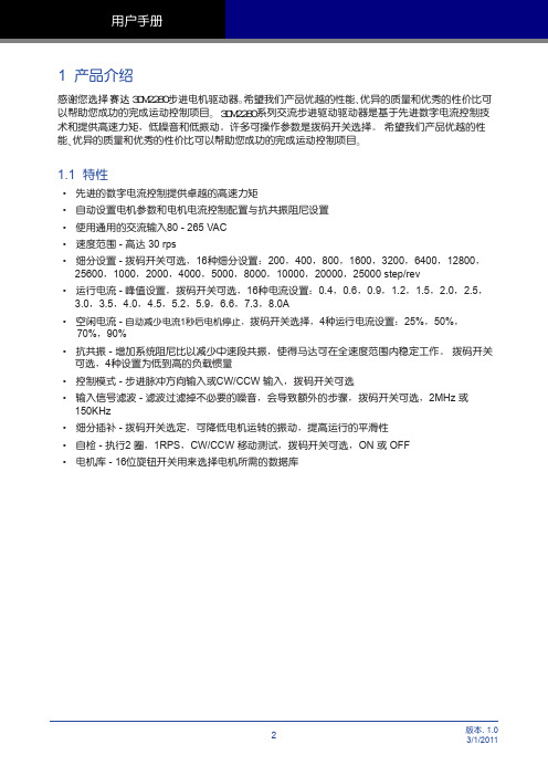
1 产品介绍
感谢您选择 赛达 3DM2280 步进电机驱动器ɻ希望我们产品优越的性能ɺ优异的质量和优秀的性价比可 以帮助您成功的完成运动控制项目ɻ3DM2280 系列交流步进驱动驱动器是基于先进数字电流控制技 术和提供高速力矩,低噪音和低振动。许多可操作参数是拨码开关选择。 希望我们产品优越的性 能ɺ优异的质量和优秀的性价比可以帮助您成功的完成运动控制项目ɻ
12800 25600 1000 2000 4000 5000 8000 10000 20000 25000
SW1 ON OFF ON OFF ON OFF ON OFF ON OFF ON OFF ON OFF ON OFF
SW2 ON ON OFF OFF ON ON OFF OFF ON ON OFF OFF ON ON OFF OFF
• 交流输入 80 - 265 VAC • 脉冲方向信号输入 • 相匹配的步进电机
状态指示灯
电机选择
故障输出 控制信号
OUTOUT+
ENEN+ DIRDIR+ STEPSTEP+
拨码开关设定
NC 电机连接 W
V U
SW16 SW15 SW14 SW13 SW12 SW11 SW10 SW9 SW8 SW7 SW6 SW5 SW4 SW3 SW2 SW1
-
开关或继电器 (闭合:逻辑低)
EN+
3DM2280
EN-
使用开关或继电器的连接方式
上位机的 灌电流
输出
OUT+ OUT-
5~24V 供电电源
-
+
EN+
3DM2280
EN-
上位机的灌电流输出连接方式
圆盘锯机说明书

370696 D-LP32/DS-TS32喜利得若本译本中内容与英文原版操作指南有所出入,则以英文原版内容为准.D-LP32/DS-TS32液压动力装置远程控制装置锯头锯片锯片护罩轨道液压软管端头止挡2目录1.基本信息 4 2.说明 5 3.系统部件、工具及附件13 4.技术数据17 5.安全预防措施21 6.用前准备27 7.操作35 8.保养与维护43 9.故障检修45 10.回收处理50 11.保证51 12.合格声明5231. 通用信息1.1首次操作设备者,作业前必须阅读操作说明。
设备必须始终配备操作说明。
设备转交他人时,请确保将操作说明一起移交。
危险标示注意此词用在有潜在危险存在的情况下,警告这些情况可能造成轻微人身伤害或者对设备或其他财产造成损坏。
1.2 象形图一般警告警告:有电警告:小心伤手戴安全手套戴护目装置戴安全帽穿安全鞋戴呼吸保护装置戴护耳装置使用前阅读操作说明始终配备锯片护罩始终配备导轨端头止挡42. 描述说明 2.1 应用范围62.2 D-LP32/DS-TS32液压锯系统部件 62.3 零件及操作控制852. 说明2.1 应用范围D-LP32/DS-TS32是重型、高性能墙锯系统的设施,可与最大直径1600 mm的锯片共用,切割深度可达73 cm。
D-LP32液压装置在63安培的电源下额定功率为32 kW,也可以在32安培的电源下运行。
它采用模块化设计,可以快速装配,具备多种用途。
例如,DS-TS32锯头可以为喜利得DS-WSS30高性能链锯系统提供动力。
采用D-RC-LP32数字遥控装置来调节无级变化的油流量时,操作者可以选择最佳的速度和最合适的前进速率。
这一特性保证了墙锯、液压钻孔、深插式墙锯和链锯的最佳效率。
2.2 D-LP32/DS-TS32液压锯系统部件基本的钻石锯系统包括以下部件:1D-LP32液压装置2D-RC-LP32遥控装置3DS-TS32锯头4D-R 200L导轨5DS-C锯片6DS-BG锯片护罩7D-PH/FH液压软管和供水软管8DS-ES-L端头止挡(每个D-R..L导轨配供2个端头止挡)9D-LP32/DS-TS32专用工具套装62. 描述2.2.1 D-LP32/DS-TS,PS,WSS和DD模组化系统D-LP32/DS-TS32墙锯D-LP32/DD-750HY/DS-PS30液压钻石钻孔机深插式墙锯D-LP32/DS-TS32/DS-WSS30链锯72. 描述2.3 零件及操作控件2.3.1 D-LP32液压装置1铰接式运输手柄2用于吊车搬运的吊装点3 400V 63A主电源插座(符合EN CEE63的欧洲标准插座)4 230V插座5用于D-RC-LP32遥控装置插座6油位观察孔7滤油器盖板8紧急停机开关9使用指南(粘贴标签)10防刺轮胎的车轮11PH3/4”接头,高压软管接头12PH3/4”接头,回流软管接头13PH1/4”接头,左右控制软管接头14PH1/4”接头,锯头摇臂接头15现场供水接头16锯头供水(附水流流速调节)17 D-RC-LP32 32遥控装置18总电源(开/关)控制开关19盖子/加油孔20 230V插座过载复位按钮21前支撑22铰链式运输手柄锁定螺栓82. 描述2.3.2 使用指南(D-LP32液压装置上的标签)92. 说明2.3.3 D-RC-LP32远程控制1遥控装置箱体2把手/控制面板保护杆3显示及操作控制4皮带扣附着点5具有皮带扣的肩带6遥控装置的后侧:切割指南7紧急停机开关2.3.4 切割指南参见RC-LP32遥控装置背面的标签。
CNC-机床说明书及维护手册讲课讲稿
6-2操作面板功能說明◆本節說明機械操作面板上各按鍵與開關之功能,按鍵與開關之位置如圖所示:模式模式說明功能說明圖例備註DNC 個人電腦聯線模式機台可以一方面與個人電腦執行程式傳輸,另一方面可以同時加工按CYCLESTART啟動按FEEDHOLD暫停EDIT 內部記憶體程式編輯模式可以編輯新的加工程式,也可以修改記憶體中舊的加工程式.(三菱系統在所有模式下都可以編輯修改)AUTO 記憶體模式機台可以執行體中的加工程式.(應先在MONITOR書面下將程式號碼呼叫了來)按CYCLESTART啟動按FEEDHOLD暫停MDI 手動操作模式可在MDI書面下,輸入簡易加工程式,並加以執行按CYCLESTART啟動按FEEDHOLD暫停HANDLE 手輪操作模式機台各軸的移動可借手輪操作盒上的軸選擇開關及倍率加以控制JOG 寸動模式機台各軸的寸動移動,可籍軸選擇開關、移動方向選擇開關及移動速率選擇開關加以控制RAPID 快速移動模式機台執行各軸的快速移動,可借軸選擇開關、移動方向選擇開關及快速移動速率選擇開關加以控制.各軸原點複歸完成前,請勿以50%或100%快速移動速率操作ZRN 原點複歸模式機台各軸執行原點複歸功能,(可選擇Z軸先原點複歸後,其他軸才能執行原點複歸功能)務必考慮各軸的原點複歸順序,避免撞機危險◆軸的移動方向移動速率選擇開關名稱功能說明圖例有效模式JOG/FEEDRATE OVERRIDE各軸的寸動及切削移動速率選擇開關,JOG模式下各軸的移動速率 mm/min為單位,DNC/AUTOMDI等模式以%為單位JOG/DNC/AUTO/MDIRAPID OVERRIDE 快速移動速率選擇開關RAPID/ZRN/DNC/AUTO/MDI+X +X 軸的移動方向選擇按鈕開關JOG/RAPID/ZRN-X -X 軸的移動方向選擇按鈕開關JOG/RAPID/ZRN+Y +Y 軸的移動方向選擇按鈕開關JOG/RAPID/ZRN-Y -Y 軸的移動方向選擇按鈕開關JOG/RAPID/ZRN◆軸的移動方向移動速率選擇開關名稱功能說明圖例有效模式+Z +Z 軸的移動方向選擇按鈕開關JOG/RAPID/ZRN-Z -Z 軸的移動方向選擇按鈕開關JOG/RAPID/ZRN+4 +4 軸的移動方向選擇按鈕開關JOG/RAPID/ZRN-4 -4 軸的移動方向選擇按鈕開關JOG/RAPID/ZRN◆主軸控制功能開關名稱功能說明圖例有效模式SPENDLE OVERRIDE 主軸旋轉轉速調整DNC/AUTO/MDT SPINDLE CW 主軸CW旋轉HANDLE/JOG/RAPID/ZRN SPINDLE STOP 主軸停止旋轉HANDLE/JOG/RAPID/ZRN SPINDLE CCW 主軸CCW旋轉HANDLE/JOG/RAPID/ZRN SPINDLE ORT 主軸定位HANDLE/JOG/RAPID/ZRN◆自動操作功能開關名稱開關說明功能說明圖例CYCLE START 程式啟動啟動程式的執行.(應先在MONITOR 書面下將程式號碼呼叫出來)。
得胜电子TS-2280立体声入耳式耳塞说明书
产品名称:TS-2280 立体声入耳式耳塞公司名称:广东得胜电子有限公司地址:广东省惠州市博罗县龙溪镇富康一路2号电话:400 6828 333 传真:+86 752 6383950邮箱:**************邮编:516121网址:Designed & Manufactured by:Guangdong Takstar Electronic Co., Ltd.Address: No. 2 FuKang Yi Rd., Longxi Boluo Huizhou Guangdong,516121China International Sales:Tel: +86 752 6383644Email: sales @ TS-2280立体声入耳式耳塞STEREOIN-EAR EARPHONE金属振膜驱动单元鼓型合金腔体Drum shape alloy cavityMetal diaphragm driver得胜公司保留对本说明书中描述的产品及说明书内容更新和改进的权利,如有更改,恕不另行通知。
如有疑问,请关注本公司的文宣资讯或网上查询:对其中涉及的描述和图像,以包装箱内内容和实物为准! Actual product may differ slightly from the description and photo of this user manual.Product is subject to update and improve without prior notice.****Notes● 驱动单元采用纯金属振膜,能带来精致、细腻的声音细节● 鼓型合金腔体,在降低机体谐振的同时提供了更加准确的低频● 温和自然的中频,完美演绎多种音乐● 合金机身采用阳极处理技术,并提供2种颜色可选● 人体工程学设计,佩戴舒适稳固● 耳机线柔软抗拉,搭配苹果线控(麦克、播放、暂停、音量、选曲)● 搭配精美皮质便捷袋;配送3种大小不同的单节、双节耳套● 产品通过Apple MFi认证,完美兼容iPhone、iPad和iPod等产品单元类型:动圈式单元直径8mm 单元阻抗20Ω±30%频率响应10Hz ~20kHz 灵 敏 度98dB at 1kHz 功率30mW额定功率15mW 耳机线Y型线总长1.4m 接驳插头 3.5四极镀金插头产品重量17.4g(:Φ:::峰值::::Φ:不含包装)姓名: 电话: 地址:商品: 型号: 购买日期 年 月 日广东得胜电子有限公司 电话: 400-6828-333 地址:广东省惠州市博罗县龙溪镇龙桥大道富康一路2号产品服务保证书线控功能要求(针对iPhone所有型号手机)1. 按下中键一次可以暂停播放歌曲或视频, 一次可以继续回放;2. 按下“+”或“-”按键可调节音量大小;3. 快速按下中键两次可以跳到下一首歌曲;4. 快速按下中键三次可以返回到上一首歌曲;5. 快速按下中键两次并按住为快进功能;6. 快速按下中键三次并按住为倒回功能;再按R注意:·本耳机只适用于CTIA接口(包括iPod、iPhone、iPad),请在购买前查阅手机说明书或咨询手机 厂商,以确认您的手机接口标准;·按键功能可能会因手机功能而异,或是否可应用于其它Android手机,视手机的型号而定;·“Voicer”功能是否可用取决于iPhone及其软件版本而定;兼容多种智能手机,iPhone 5S iPhone 5C iPhone 5 iPhone 4Siphone、Android部分机型:iPhone6 Plus iPhone6关于版权“Made for iPod ”、“Made for iPhone”、“Made for iPad ”表示专为iPod、iPhone、 或iPad而设计的电子附件,并经开发者认证符合Apple性能标准。
P280 使用手册说明书
P280 UserManualP280 User Manual Congratulations on your purchase of the Antec P280!Sophisticated and cutting-edge, the P280 emphasizes the ease of use, quiet technology and unparalleled performance characteristic of Antec’s Performance One series. This advanced enclosure comes equipped with features that will maximize your PC experience, from Quiet Computing™ panels & HDD drive bays, to grommet-lined cable routing holes with ample space behind the motherboard tray. TheP280 accommodates motherboards up to XL-ATX and includes nine expansion slots to support up to four 13.0” / 330 mm graphics cards. And with convenient tool-less optical drive bays, easy-access front & bottom PSU intake air filters, two front panel USB 3.0 ports and an affordable price, you get an elite enclosure that will last you for builds to come.The P280 does not include a power supply. Make sure you choose a power supply that is compatible with your computer components and has a long enough power harness to reach your motherboard and peripheral devices. We recommend our High Current Gamer, High Current Pro or EarthWatts power supplies for the latest ATX specification compliance, broad compatibility, and power savings capability. At Antec, we continually refine and improve our products to ensure the highest quality. As such, your new chassis may differ slightly from the description in this manual due to improvements applied for the optimal building experience. As of November 15, 2011, all features, descriptions, and illustrations in this manual are correct.Table of Contents Section 1: Introduction1.1Getting to Know Your Chassis (5)1.2Chassis Specifications (6)1.3Included Screws (6)1.4Before You Begin (7)Section 2: Hardware Installation2.1 Setting Up (9)2.2 Motherboard Installation (9)2.3 Installing KUHLER H2O Liquid Coolers (11)2.4 Power Supply Installation (12)2.5 External 5.25” Device Installation (13)2.6 Internal 2.5” Device Installation (14)2.7 Internal 3.5” / 2.5” Device Ins tallation (14)2.8 Cable Management (16)Section 3: Front I/O Ports3.1 USB 2.0 (18)3.2 USB 3.0 (18)3.3 AC’97 / HD Audio Ports (19)3.4 Power Switch / Reset Switch / Hard Disk Drive LED Connectors (19)3.5 Rewiring Motherboard Header Connections (20)Section 4: Cooling System4.1 Included Fans (22)4.2 Optional Fans (22)4.3 Air Filters (24)Section 1 IntroductionP280 User Manual1.1 Getting to Know Your Chassis1. 3 x 5.25” tool-less drive bays2. 2 x 2.5” drive trays (dedicated)3. 6 x 3.5” / 2.5” drive trays4. 2 x 120 mm top TwoCool™ exhaust fans5. 1 x 120 mm rear TwoCool™ exhaust fan6. 2 x 120 mm internal intake fans (optional)2 x 120 mm front intake fans (optional)7.9 expansion slots8.CPU cutout9.Cable routing holes10.Motherboard mount: XL-ATX, Standard ATX, microATX or Mini-ITX11.Power supply mount / PSU intake filter12.Front Ports (USB 3.0, USB 2.0, Audio I/O)1.2 Chassis Specifications1.3 Included ScrewsAn inventory of all screws and intended usage and quantity is provided here:A. Power supply screw (4)B. Motherboard standoff (4 included, 6 preinstalled)C. Motherboard screw (10)D. Optional 5.25” screw / dedicated 2.5” drive bay screw (6)E. 3.5” tray -mount screw (25)F. 2.5” tray -mount screw (8)G. Front fan screw (4)H. Not pictured : zip ties for cable management (6)A B C D E F1.4 Before You BeginIn order to ensure that your building experience with the P280 will be a positive one, please take note of the following:∙While working inside your P280, keep your chassis on a flat, stable surface. Make sure your build environment is clean, well-lit, and free of dust.∙Antec chassis feature rounded edges that minimize the occurrence of hand injuries.Nonetheless, exercise caution and control when handling chassis interiors. We stronglyrecommend taking the appropriate time and care when working inside the chassis. Avoidhurried or careless motions.∙Handle components and cards with care. Do not touch the unshielded components or contacts on a card. Hold a card by its edges. Hold a component such as a processor by its edges, never by its pins.∙To avoid electrostatic discharge, ground yourself periodically by touching an unpainted metal surface (such as a connector or screw on the back of this computer) or by using a wristgrounding strap.∙Before you connect a cable, ensure that both connectors are correctly aligned and oriented.Bent pins can be difficult to fix and may require replacement of the entire connector.∙This manual is not designed to cover CPU, RAM, or expansion card installation. Please consult your motherboard manual for specific mounting instructions and troubleshooting. Beforeproceeding, check the manual for your CPU cooler to find out if there are steps you must takebefore installing the motherboard.∙Do not sit on your chassis. Although it is constructed of heavy-duty steel and internally reinforced, it is not designed to support the weight of an adult, and may buckle.∙Remember to use the right tools for each task. Do not use improvised screwdrivers like coins, nails or knife blades as they may result in damage to screw threads or even injury. Do not useyour fingernails to separate edges or lift the sides of the chassis, as paint chipping or injury may occur.Section 2Hardware InstallationP280 User Manual2.1 Setting UpPut the case upright on a flat, stablesurface so that the rear panel (powersupply and expansion slots) is facing you.To remove the left and right side panels,remove these thumbscrews first.Note : Place the panel thumbscrews asidecarefully and remember where they are.Remove the panel by gripping the end ofthe panel at the top & bottom andswinging the panel outward. Do not pullthe panel back toward the rear of thechassis.CAUTION: Do not use your fingernails to pry or lift the panels. Damage to the panels or injury to your fingernails may result.2.2Motherboard InstallationBefore proceeding:Check the manual for your CPU cooler to find out if there are steps you must do before installing the motherboard.Make sure you have the correct I/O panel for your motherboard. If the panel provided with the chassis isn’t suitable, please contact your motherboard manufacturer for the correct I/O panel.Remove the panel by the end of the panel at the top & bottom andswing the panel outward.The P280 comes with six preinstalled motherboard standoffs. These are positioned for Standard ATX motherboards but can be relocated to accommodate other form factors.1.2.3. Screw your motherboard into the standoffs with the provided motherboard mounting screws.Use the provided motherboard mounting screws to secure yourmotherboard into the standoffs.2.3 Installing KUHLER H 2O Liquid CoolersThe following instructs how to install the Antec KUHLER H 2O liquid CPU cooler (620 / 920). For any other CPU coolers, please consult your manufacturer’s installation guide.Caution :Check your motherboard’s CPU socket to ensure its compatibility with the KUHLER H 2O. The KUHLER H 2O 620 / 920 is compatible with the following CPU sockets:Intel® LGA 1155 / 1156 / 1366 / 2011* AMD® AM2 / AM3 / AM2+ / AM3+ / FM1*Your unit may not contain the LGA 2011 mounting bracket. To acquire this, please contact Antec customer support (information listed at end of manual).**Be sure to install the KUHLER H 2O with the end of the tubes positioned at the bottom of the radiator.1.fan.2. Remove the screws on the back of the chassis whilesupporting the fan with your other hand.3. Preparing the KUHLER H 2O backplate is specific to your CPU socket. Please refer to the KUHLERH 2O installation guide, available at/Believe_it/product.php?id=Mjc2OCYxNw== (KUHLER H 2O 620) or/Believe_it/product.php?id=NzA0MzcwJjE3 (KUHLER H 2O 920) for more information.4. Prepare the retention ring according to the CPU socket you’re using.5. Complete installation according to the KUHLER H 2O instructions.2.4 Power Supply Installation1. With the case upright, place the powersupply as illustrated in the image to the right.2. Push the power supply to the back of thecase and align the mounting holes.3. Attach the power supply to the case withthe screws provided.**See Section 4.3 for PSU filter removal instructions2.5 External 5.25” Device InstallationTo install a 5.25” drive, you will need to remove the side panel and open the front door. For side panel removal, please see Section 2.1.1. With the side panel off, carefully push the drive bay cover out of the drive bay.2. Slide your 5.25” drive through the front of the chassis until it lines up flush with the front bezel.You will feel the drive lock into position.3. If you need more clearance on the inside of the chassis for your drive, pull the drive bay tab onthe inside of the chassis toward you and push the drive in further.2.6 Internal 2.5” Device InstallationThere are two dedicated 2.5” drive bays in the P280. To install a 2.5” drive:1.With the side panel open, slide your2.5” drive into the drive bay so that the drive’s holes alignwith the drive bay holes.2.Secure your drive with the 2.5” screws provided (D in Section 1.3).The P280 has six drive bays that are compatible with both 3.5” and 2.5” drives.To install a 3.5” drive:1.Remove one of the drive trays by pinching the ends of the tray inward and pulling the drive trayout.2.Place your3.5” drive on the tray so that the holes line up with the silicone grommets.ing the 3.5” drive screws (E in Section 1.3), secure your 3.5” drive to the tray. We recommendusing your hand to find the exact threading of the drive’s holes then u sing a screwdriver tocompletely secure your drive. Do not over-tighten the screws as this will minimize thegrommets’ ability to reduce vibration.4. Now that your drive is secure to the tray, pinchthe ends of the tray and insert your drive into the bay. You will hear your device click into place.To install a 2.5” drive:1. Extract one of the drive trays by pinching the ends of the tray inward and pulling the drive trayout.2. Place your 2.5” drive on the tray so that the holes line up with the 2.5” tray holes.3. Using the 2.5” drive screws (F in Section 1.3), secure your 3.5” drive to the tray with ascrewdriver.4. Now that your drive is secure to the tray, pinch the ends of the tray and insert your drive intothe bay. You will hear your device click into place.**If you need to install additional 5.25” drive ba ys, please remove the metal cover adjacent to the plastic drive bay cover.Pinch the ends of the tray and insert your drive until it clicks.Use the grommet-lined cable routing holes to route PSU cables. The yellow circle shows a cable tiedown.2.8 Cable ManagementThere is a cable management compartment between the motherboard and right side panel, as well as cable tiedowns located on the back of the motherboard panel. You can tuck excess cables in this compartment or route them to the drive bays.Choose the cables you would like to pass through the holes behind the motherboard tray. Pull them through the hole toward the right side of the case.Use the zip ties provided to hold your cables in place. Zip ties can be anchored to tiedown locations located on the back of the motherboard panel.For cables which will be routed back to front drives or other internal accessories, feed the cables backthrough the insertion point nearest thedestination of the cable. Connect thecable and then pull the slack back to the right side of the case.For cables which will be routed directly to front drives or other internal accessories, cable tiedowns are located along the drive cage. Bundle front drives’ or other internal accessories’ cables together and secure them using tiedowns.Section 3Front I/O PortsP280 User Manual3.1USB 2.0Connect the front I/O panel USB cable to the USB header pin on your motherboard. Check your motherboard user’s manual to ensure that it matches the table below:3.2 USB 3.0The P280 comes with two front panel USB 3.0 ports and includes an internal motherboard connector. To access USB 3.0 capability from the front panel:1. Identify the USB 3.0 header on your motherboard.2. Connect the USB3.0 header to the motherboard port. Besure to align the connector in the proper orientation so that you do not damage the pins on your motherboard.1 29 10 Align the connector properly to prevent damage to yourmotherboard.3.3 AC’97 / HD Audio PortsThere is an Intel® standard 10-pin AC’97 connector and an Intel® 10-pin HDA (High Definition Audio) connector linked to the front panel of the chassis.You can connect either the AC’97 or the HDA connector, depending on your motherboard. Locate the internal audio connectors from your motherboard or sound card and connect the corresponding audio cable. Consult your motherboard or sound card manual for the pin-out positions. Even if your system supports both standards, only use one connector.3.4 Power Switch / Reset Switch / Hard Disk Drive LED ConnectorsConnected to your front panel are LED leads for power and HDD activity, as well as switch leads for the power and reset buttons. Attach these to the corresponding connectors on your motherboard. Consult your motherboard manual for specific pin header locations. For LEDs, colored wires are positive ( + ). White or black wires are negative ( – ). If the LED does not light up when the system is powered on, try reversing the connection. For more information on connecting LEDs to your motherboard, see your mothe rboard user’s manual.Front panel leads3.5 Rewiring Motherboard Header ConnectionsThere may come a time when you need to reconfigure the pin-out of a motherboard header connector. Examples could be for your USB header, audio input header, or some other front panel connector such as the Power Button connector.Before performing any work, please refer to your motherboard user’s manual or your motherboard manufacturer's website to confirm the pin-out needed for your connector. We strongly recommend making a notated drawing before beginning work so that you can recover if your work gets disturbed.Determine which wires you need to remove in order to rewire your plug to match the USB pin-outs on your motherboard (refer to your motherboard user’s manual). Working on one connector at a time, use a very small flathead screwdriver or similar tool to lift up on the black tab located beside the gold posts (squares). This will allow you to easily slide out the pins from the USB plug.Working carefully so as not to damage the wires, connectors, or pins, slowly remove the pin from the connector. Repeat these steps for each wire you need to change.Working carefully so as not to damage the wires, connectors or pins, slowly insert the pin into thecorrect slot of the connector then snap closed the black tab that was lifted in step 1. Repeat these steps for each wire you need to change.Front panel headersSection 4 Cooling SystemP280 User Manual4.1Included FansThe P280 comes with two standard top 120 mm TwoCool™ fans and a standard rear 120 mm TwoCool™ fan. These fans have two-speed switches on the rear of the case that let you choose the speed best suited to your need. The default fan speed setting is Low.120 mm TwoCool™ fan specifications:Size 120 x 25 mm two-speed fan Rated Voltage 12V DC Operating Voltage: 12V±10%4.2 Optional FansThe P280 includes mounts for up to four more fans. These mounts are as follows:∙ 2 x front intake 120 mm mounts ∙ 2 x internal intake 120 mm mountsFront intake 120 mm fansYou can install these fans using 2 of the long screws provided (G in Section 1.3). Align the fan with the screw holes and screw in the fan in the top-left and lower-right holes (as pictured).Internal intake 120 mm fans Array Just outside of the 3.5” drive bay area are two fan mounts for 120 mm internal intake fans.1.Align your fan with the pegs thatcorrespond with the fan screwholes on the fan.2.Push your fan into the slot untilsecure. You will hear your fanlock into place when the bracketsaround the fan snap into place.4.3 Air FiltersThere are two filters in the P280 that can be removed and washed. One filter is the front filter and the other is the PSU intake filter. You can access the front filter by opening the front door and pushing down on the tabs at the top of the filter.Note: From time to time it will be necessary to wash theinstalled air filter. Not washing the air filter will result inhigher system temperatures and possible stabilityproblems. We recommend checking the air filter at leastonce a month initially. The frequency will changedepending on system usage (users whose systems run24/7 will likely have to check/wash more often thanthose who don’t use their systems every day) and onenvironmental conditions.The P280 features a removable PSU filter that can be unlocked for maintenance and locked for transport.To remove the PSU filter, push the ends of the filter down then pull the filter toward you using the tab outside of the chassis. You can also lock the filter by pushing up on the tab (once the filter is completely inside the chassis).Antec, Inc.47900 Fremont Blvd.Fremont, CA94538tel: 510-770-1200fax: 510-770-1288Antec Europe B.V.Stuttgartstraat 123047 AS RotterdamThe Netherlandstel: +49-40-226139-22fax: +31 (0) 10 437-1752Technical SupportUS &Canada1-800-22ANTEC*************************Europe+31 (0) 10 462-2060****************************© Copyright 2011 Antec, Inc. All rights reserved.All trademarks are the property of their respective owners. Reproduction in whole or in part without written permission is prohibited.。
电话机使用说明书
1820C型电话机使用说明书一、简要说明感谢您选择1820C型电话机,此产品可用于家庭分机使用及酒店专用电话机。
您可以通过阅读本手册,全面地了解901电话机的使用,领略其完善的功能和简洁的操作方法。
二、产品功能1)拨号暂停功能2)最后一组号码重拨3)静音功能三、产品安装及使用1.打开彩盒,取出电话机与2根电话线,把话筒曲线一头(两头不分)插入主机左侧面的插孔,另一头插入话筒手柄的插孔;将另外一根电话线(两头不分)一头插入电话机后面的插孔,另外一头插入墙板的电话口。
2.打开主机背后的电池盒后盖,按照正确的+-极性装入3节7号电池,盖上后盖,此时电话机屏幕应该有显示,否则电池没有装好请重新检查直至屏幕显示正常;3.提起话筒,听筒应该听到“嘟--”拨号提示音,说明接通,可以正常使用了。
如果无声,请检查电话进线是否接触正常。
看图:四、产品常见故障现象及维护方法1、铃声异常(1)电话机挂机时铃响不断。
一般是电话机振铃电路中的电容被击穿短路,使收铃器输入失去直流作用。
挂机时外线直流外线馈电电压为振铃集成IC提供工作电源,所以挂机时铃响不断。
一般只要更换打振铃电容就可以了。
如果振铃电容没坏,应检查抑制电路板是否漏电或是否由于焊点处理不当而短路。
(2)铃声小。
检查在收铃状态下集成IC的直流电压是否为25~27V。
若低于正常值较多,应检查输出耦合电容是否漏电或击穿短路,若电压基本正常,应检测输出衰减电阻阻值是否变大,开关、线圈是否局部短路,否则就是IC性能不良。
2、无振铃当电话机出现无振铃故障时,要在振铃状态下按以下步骤检查。
①测量整流桥输入交流电压。
正常时约为60V;若接近0V,应检测振铃电容和降压电阻是否断路,开关是否损坏或引线是否脱焊。
②测量振铃IC的直流电压。
正常时为25~27V;若接近0V,应检查整流、滤波电路是否被击穿短路,整流桥是否有二极管损坏,否则就是振铃IC内部短路。
3、无送话用镊子碰通话集成IC时,从受话放大器中听到感应交流杂音,说明是送话输入电路有问题,应检查话筒线、送话器及供电可调电阻是否良好;外围元件是否接触不良。