HZF-S2闸门开度荷重智能测控仪说明书(SSI信号和电流信号)
ZMK-2闸门开度仪说明书

“0000”且第一位闪动,通过 、 、 键将此值修改为“1999”
按 S 键仪表显示“LL”此时确认闸门所在的位置是零点,然后按
键零点设定完成并自动退出。
再启动闸门,看仪表的显示,如仍为零,则可能是闸门开向反了。
按说明书的设置正反转操作。
1. 设置量程、海拔高度、圈长:
同时按 S 和
键,仪表显示值为 0000 且第一位闪动,通过
同时按s键仪表显示值为0000且第一位闪动通过键将密码0002输入再按s键仪表显示lc表示已经进入量程设置仪表显示0000将四位数的量程置入再按s键仪表显示hb表示已经进入海拔高度设置仪表显示000000将六位数的海拔高度植入再按s键仪表显示l表示已经进入圈长设置再按s键显示上次设定值圈长表示开度传感器内部齿轮变出出厂已设置好用户无需调整最后按s键退出
技术参数:
测量信号:旋转编码器 测量精度:非线性度<0.25% 数显内容:开度值,4 路报警输出整定值。 开关量输出信号:4 路,每点可由用户在所定范围内整定。 模拟量输出:4-20mA 输出接点容量:5A/250VAC,5A/30VDC 工作环境:温度 0-50℃ 湿度<85% 外形尺寸:盘装 160*80*250mm 工作方式:连续 电源:110V/220VDC 或 AC110/220V/50Hz 功耗:10W
1
4.4 路输出信号经过放大后驱动继电器输出,其中 4 个动作点与报警 值所设定的对应,闸门达到开度设定值时,对应输出接点动作。 5.先进的 WATCHDOG 和电压监控电路能对计算机的工作情况进行 监控,当上电、掉电或电压不稳时,符合工业 SPT 标准的串行存储 器能保护计算机中的信息。当计算机死机时,看门狗能自动产生复位 信号重新启动计算机工作,大大提高了仪器的可靠性。 6.采用稳态开关电源,交、直流均可稳定工作,且电压变化不影响测 控装置可靠工作。
AUR°EL HCS-Keeloq 无线磁电子门窗传感器说明书

User ManualLe caratteristiche tecniche possono subire variazioni senza preavviso. La AUR°EL S.p.A non si assume la responsabilità di danni causati dall’uso improprio del dispositivo.WIRELESS MAGNETIC CONTACTThe magnetic contact wireless MAG HCS is a sensor able to detect opening or closing doors or windowsand transmits via radio a alarm signal. It is composed of two distinct elements: a case containing the magnetic contact and electronic card normally placed on the frame of the fixture and a small permanent magnet to fit on the mobile element of the fixture. The working is based on the closing and opening of a sensor capable to operate within a 10-15mm radius from the permanent magnet.MAG HCS is battery power by (CR2032) supplied and designed to ensure autonomy of 2-3 years, it is always internallycontrolled by a meter charge that forwards via radio the battery life time and warns by a beeper and LED, the alarm of discharged battery.It’s available a double auxiliary block terminal independent from internal magnetic contact, where it’spossible to connect a second sensor, eg further magnetic contact, sensor for rolling shutters or other type of sensor that uses a free NC contact. Internal electrical card manages this independent contact and the event of case opening and consequent sends a unique radio code.Other functionalities are: the tamper, which is activated in the event of tampering of the enclosure, the tear can be activated by removing of the sensor installed, a software periodic supervision that communicates via radio the battery status, tamper, magnetic contact independent alarm condition. The radio protocol is a rolling code type, and unique code programmed in AUREL for each sensor. A LED shows radio transmissions, alarms and test.Fig.1 – Sensor and magnetFig. 2 – PCB sensor side1) Sensor2) Permanent Magnet3) Dip switch: not assembled in HCS version4) Jumper 1-4: Setting mode (see "Sensor Configuration). 5) Reed:select magnetic contact with open JP36) Reed: select magnetic contact with closed JP37) Tamper: tamper switch8) Aux In:AUX INPUT9) Battery:batteria mod. CR2032 tipo Litio10) Buzzer:Low battery indicator11) LED:light signals (see signaling) 12) Antenna:please do not modify it* HCS and Keeloq are brand Microchip3JP1 JP2JP3 JP4 6 5127 8124User ManualLe caratteristiche tecniche possono subire variazioni senza preavviso. La AUR°EL S.p.A non si assume la responsabilità di danni causati dall’uso improprio del dispositivo.Fig. 3 – battery PCB sideSensor configurationJumpers allows to setup different operation mode and tests. Do not activate at the same time jumper JP1 and JP2, if you activate jumper JP1, be sure JP2 is not active! After 10 minutes from last jumper status change, sensor configuration mode is off, in order to reset this configuration, take off the battery and insert back after tamper button will press.JP1 Radio Mode JP2 SupervisionJP3 Magnetic contac selection JP4 Magnet settingTab.1 – sensor config.RADIO MODE: allows to verifythe radio link between sensor and receiver. It’s activate once JP1 is closed. Radio transmission works for 30 seconds, then switch on normal works.SUPERVISION FUNCTION : It sends to the receiver side a signal to give a feedback of the status battery and the status of the magnetic, tamper , tear contacts.It’s activated from the closing of JP2 contact, it’s foreseen a transmission each 60 seconds independent from the alarm signal.CALIBRATION OF MAGNETIC SENSOR: It’s a function used during learning procedure of the sensor that helps the installer to place the permanent magnet near the magnetic contact.It is triggered by the closure of JP4 the LED switches on when the magnet closes the magnetic contact and switches off when the contact opens. No radio transmission is activated.After 5 minutes from the starting of the procedure, the sensor will come back to the normal function. To start again the function, disconnect and fit again JP4.MAGNETICCONTACTSELECTION: allows to select, if both are present, one magnetic contact REED depending from the assembly. Selection is made by JP3 if closed, active contact is the one fitted on the large PCB side, if open is the one fitted on the short PCB side.JP3 closed Reed active on large PCB side JP3 open Reed active on short PCB side1012911User Manual MAIN WORKING:Normally is activated after the fitting of the battery or when “RADIO MODE” AND “CALIBRATION OF MAGNETIC SENSOR” functions are finished. The sensor sends the status code when there is a variation of the operation, eg opening or closing of any contact (see "SPECIFICATIONS OF THE RADIO CODE). The led switches on for 100 ms to show the transmission. The time transmission is about 1 sec.Acoustic and luminous signal.are present 1 buzzer and 1 red LED with the following functions:BUZZER: Used to signal low battery and it’s activated when the battery voltage drops below 2.35 volts with a duration time of 2-3 seconds.LED is activated for each radio transmissions (alarm, supervisory radio test). If the case of low battery (below 2.35 V), it blinks quickly for 2 seconds every 5 minutes. The calibration function of the magnetic sensor remains on when the magnetic contact is closed.Technical featuresMin Tipico Max UnitàPower supply (1) 2.1 3 3.3 VCurrent consumption Tx 12 15 mACurrent consumption stand-by 4.0 5.0 6.5 uALow battery 2.1 2.25 2.35 VoltBattery life 2 (1) 3 yearsRadio transmissionStandard frequency OOK modulation433.82 433.92 434.02 MHzModulation OOK On-Off KeyingEffected Radiated Power (E.R.P) 0.5 1.0 mWERP second harmonic < 1GHz -36 dBmERP third harmonic > 1GHz -30 dBmElectromagnetic immunity10 V/mCodifica KeeloqSerial code 28 bitHopping code 32 bitHopping combos 2³² -Working temperature-10 +55 °CCase Dimension 70,4 x 33,6 x 17,4 mm(1) Tipo Litio 3V CR2032Radio code featuresMAG 4MHCS implements the Microchip's Keeloq rolling code with Aurel manufacturer code, customizable on request. The parameters of the protocol Microchip Keeloq are not disclosed and are available on request. The radio transmitted codes related to different functions of MAG HCS are described below. Consider that the S0-S1-S2-S3 codes refer to the 4-bit encoding used by Keeloq (see the documentation about the Microchip Keeloq):Le caratteristiche tecniche possono subire variazioni senza preavviso. La AUR°EL S.p.A non si assume la responsabilità di danni causati dall’uso improprio del dispositivo.User ManualLe caratteristiche tecniche possono subire variazioni senza preavviso. La AUR°EL S.p.A non si assume la responsabilità di danni causati dall’uso improprio del dispositivo.MAGNETIC CONTACT: represented by S3 bit and it has high logic level when the contact is opened or low logic level when the contact is closed.TEAR AND TAMPER CONTACT: they use the same bit S2 and it goes high when one of the two contacts is open. S2 goes low when both are closed.AUXILIARY INPUT: represented by S0 bit and it goes high when the contact is open and low when it’s closed.RADIO MODE: all bits (S0-S1-S2-S3)are at “zero” logic level and this function is used for test radio transmission or learning the radio code in the central unit.SUPERVISION: represented by S1 bit it has high logic level once radio code Supervision is emittedFig.4 –Back frameFig.5 – Back sensorInstallation:1)Place the back frame (fig. 4)on the fixture making sure to turn the magnetic sensor tothe moving part of the frame where the permanent magnet is placed. Then mark the holes printed on thebottom box (see fig. 3), 5-6 mm drill with drill and secure the bottom2)Place the permanent magnet on the mobile part of the fixture trying to match the reference marksin thecase of the sensor and permanent magnet. If the magnet is sufficiently close to the magnetic contact, LEDwill switch on indicating the closure of the magnetic contact. However, the sensor will not be installed at a distance greater than 30mm from the permanent magnet.Fixingholes hookshooksUser Manual Learning procedure and radio test:Prepare the receiver side in the learning mode.Activate the "radio mode" of the MAG 4MHCS by closing JP1 and JP2. The radio will operate for about 30 seconds.Note: The installation of MAG HCS on metal frames can cause radio performance losses. In this case it is advisable to install the magnetic sensor away from screening components and connect an external magnetic contact to the auxiliary inputInstallation with connection to the auxiliary input.Il MAG HCS implement intermally a NO contact, usable from a another sensor The figure above shows a typical application of sensors connected in series to help protect a single device with multiple windows. The various contacts must be connected in series, the opening of one of them will cause the alarm. This scheme will not allow the state opening of each frame.This contact can also be used with any other type of sensor that has a dry contact output NO / NC.Fig.7 – Principio di utilizzo e collegamento del contatto ausiliario del sensore magneticoBattery substitutionThe substitution of the battery must be carried out when the sensor transmits the low battery alarm by radio signal or led or buzzer. However the battery is not completely discharged and will ensure a couple of weeks of working.To substitute, procede as follow:remove the top side of the case, replace the 3V mod. CR2032 litium battery being careful to the polarity, see picture number 8. To obtain a higher time life, five years life time batteries are advised. The accidental reversal of polarity of the batteries does not cause the breaking of the circuit and discharging them. In the case of loosing of substances , remove it taking care to not get in contact with them. Throw used batteries in respect of the normative. See the section 'Information for users'.Le caratteristiche tecniche possono subire variazioni senza preavviso. La AUR°EL S.p.A non si assume la responsabilità di danni causati dall’uso improprio del dispositivo.User ManualLe caratteristiche tecniche possono subire variazioni senza preavviso. La AUR°EL S.p.A non si assume la responsabilità di danni causati dall’uso improprio del dispositivo.Fig. 8 – battery substitutionINFORMATION FOR THE CUSTOMERThe product you purchased, must be separately throw and it can not be thrown as municipal waste, as required by Directive 2002/96/EC. Therefore, this system and all its components, subsystems andconsumables materials that are part of the product, when you take the decision to discard them, must be thrown to collection centers for proper treatment of waste, according as provided by law. To know where these centers are located, you should ask at the municipal offices.CE DECLARATION OF CONFORMITYThe magnetic contact MAG 4MHCS is under the follow normative: ETSI EN 301 489-3 V1.4.1 – Electromagnetic compatibility ETSI EN 300 220-1 V2.3.1 – Radio features EN 60950 – Other featuresCE ReferenceIn the back of the plastic case that encloses the transmitter is present a label with the identification of the module as those reported here at the left side [product name, manufacturer, voltage supply and currentsupply].+ on the top- on the backPull the battery。
闸门开度仪

Sel 为方波输出信号,可用作 L/R 左右选通信号。
D1~D8,Hh 为开关量推拉输出,对应于: D1---HA 参 数 动 作 点 ;D2---Ho 参 数 动 作 点 ;D3---H1 参数动作点 ;D4---H2 参数 动 作 点 ;D5---H3 参数动作点 ;D6---da 参数 右 动作点 ;D7---da 参数 左 动作点 ;D8---Hc 参数动作 点;Hh---db 参数动作点;Vs 为推拉输出供电源正,Gnd 为地。
设置 P
P+5
P+10 P+15 P+20
修改密码 当前置位高度 报警极限位置动作上限(D1) 全开(工作最大)位置动作上 限(D2) 下滑H1相对于Ho变化位置(D3) 下滑H2相对于Ho变化位置(D4) 中间工作位置动作上限(D5) 全关位置动作上限(D8) 左右超差动作上限(D6,D7) 左右极限超差动作下限(D9) 转向(0~3) 小数点(0~3) 显示最大值 显示最小值 继电器延时(0~255) 4mA对应高度 20mA对应高度 右4mA调零 右20mA调满 左4mA调零 左20mA调满 平均/左右独立 (1/0) 电流输出 BCD/二进制输出(1/0) 系统高度校准系数(0.8~1.2) 逐点修改 显示闪烁后恢复出厂曲线值 传感器工作点数(n<=16) 每点对应的圈数 按点输入高度计算表
, 23 30 31 0D,返回 = + 000000001)
指令格式 :详见通讯协议。 变送输出零位调整 变送输出的零位(下限)和满度位(上限)在出厂前已调好,在实际使用中如发现偏差,可先微调, 方法是先将 Lo 设定为变送输出下限值,退出设定并置位,测量变送输出值(零位) ,如有偏差,进入设 定状态的 BA0,上下调整参数,同时测量变送输出值,直到达到要求确定退出。 以上的调整只能是微量的偏差,调整方式是平移,调整后,其满度位也有微量平移。如仍无法达到 零位与满度位的准确要求, 也可进入线性化调整, 方法是先置位 Lo 到变送下限位, 进入特别设置状态 (OA 密码 006210) ,设置参数 BA0,上下调整参数,同时测量变送输出值,然后置位 Lo 到变送输出满度位,进 入特别设置状态(OA 密码 006210) ,设置参数 BAC,上下调整参数,同时测量变送输出满度位值,达到要 求确定退出;此方法需上下限多次调整至上下限均达到要求
闸门开度测控仪使用说明书

闸门开度测控仪使用说明书V2.0济南智泽贸易有限公司目录1、概述 (2)2、技术指标 (2)3、工作原理 (3)4、面板布置及使用方法 (4)5、安装与调整 (7)6、注意事项 (14)7、低功耗说明 (14)8、质保与售后 (15)9、联系方式 (15)10、免责声明 (15)一、概述闸门开度远控测控仪,是根据水利工程的实际需要而制造的,它和绝对编码器相配合组成闸门开度测控装置。
闸门开度测控仪采用微电脑控制技术,具有测量值和设定值数码显示;输入输出电路采用光电隔离技术;四个继电器动作(上限、下限、上升-自动启门、下降-自动闭门),远程讯响提示(选配),继电器动作预置参数由仪表面板的按键(或远程上位机)完成,继电器动作时相应的指示灯点亮、蜂鸣器发出报警(静、响可控)功能。
RS485串行通讯接口等。
该仪表通过内部设定可修改编码器的增量方向、仪表地址编号、内部分段修正系数等,相对零点,用户可轻松地查看和设置,是理想的闸门开度(远控)测控仪表。
下图为闸门开度测控装置结构示意图:二、技术指标1、测量范围:0~9999mm(或0-9999cm)2、分辨率:1mm/或1cm3、精度:±0.1%×量程±1mm/或1cm4、闸门扬程-开度非线性修正系数:(16段)用户可自行调节5、输入信号:SSI接口(同步串行格雷码);(来自于开度编码器,输入至仪表后面板上的DB25端子);6、输入接点信号(光电隔离):输入接点通道3-7路(一般为3路)外部接点入信号处理开度信号微处理器按键接口4-20mA输出RS485接口声光报警继电器输出设定值LED显示测量值LED显示7、通讯接口:RS485串行通讯接口(支持MODBUS-RTU 协议)8、输出信号(光电隔离):4-20m 标准模拟量输出(对应值可自行调节)(选配)9、输出接点:●上限:测量值大于等于上限值,声、光报警,上限继电器动作;●下限:测量值小于等于下限值,声、光报警,下限继电器动作;●上升:自动启门。
开度仪使用说明
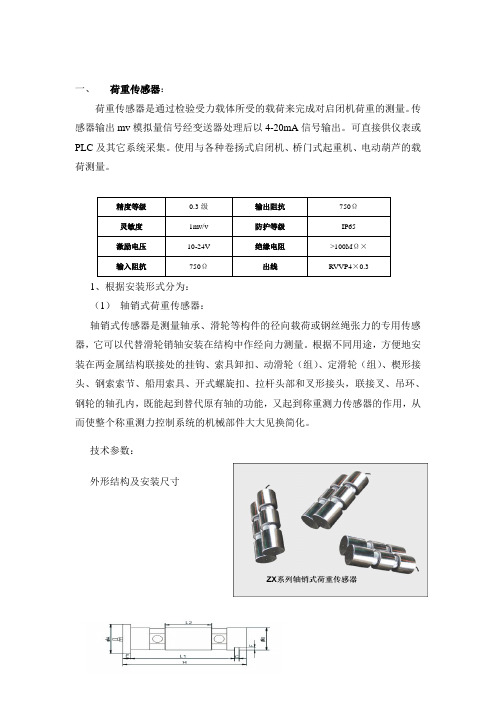
一、荷重传感器:荷重传感器是通过检验受力载体所受的载荷来完成对启闭机荷重的测量。
传感器输出mv模拟量信号经变送器处理后以4-20mA信号输出。
可直接供仪表或PLC及其它系统采集。
使用与各种卷扬式启闭机、桥门式起重机、电动葫芦的载荷测量。
1、根据安装形式分为:(1)轴销式荷重传感器:轴销式传感器是测量轴承、滑轮等构件的径向载荷或钢丝绳张力的专用传感器,它可以代替滑轮销轴安装在结构中作经向力测量。
根据不同用途,方便地安装在两金属结构联接处的挂钩、索具卸扣、动滑轮(组)、定滑轮(组)、楔形接头、钢索索节、船用索具、开式螺旋扣、拉杆头部和叉形接头,联接叉、吊环、钢轮的轴孔内,既能起到替代原有轴的功能,又起到称重测力传感器的作用,从而使整个称重测力控制系统的机械部件大大见换简化。
技术参数:外形结构及安装尺寸注:相关及不尽参数可根据用户需要设计、修改 (2) 轴承座式荷重传感器:轴承座式荷重传感器,主要用于轴承座中心高不够的场合,或把传感器其作为起闭机的轴称座使用。
这种传感器采用两端支撑,抗侧向力和抗冲击性能好,安装使用方便,一般也可以做成4—20mA 二线制输出。
技术参数外型结构及安装尺寸注:相关及不尽参数可根据用户需要设计、修改(3)定滑轮式荷重传感器定滑轮式荷重传感器,主要安装于定滑轮轴下,也可以用于在平衡滑轮轴等其他形式的轴下,常用于起重限制器的传感器。
用其作为滑轮座来测量载体的重量。
特点:采用两端支撑,中间受力的桥式结构,恰似两个完全相同的悬臂梁传感器对接在一起。
量程范围广,测量精度高,性能稳定可靠,抗侧向力和抗冲击性能好,安装使用方便。
一般也可做成4—20mA二线制输出。
技术参数外形结构及安装尺寸(3)旁压式荷重传感器旁压张力传感器安装方便、操作简单、维修容易,专用于测量钢丝绳的张力。
钢丝绳通过U 形螺栓固定在传感器上,当钢丝绳受拉力时,力通过导向轮作用于传感器上。
技术参数:。
HZF-S1型 闸门开度智能测控仪说明书(JDZ-G编码器信号)

HZF-S1型闸门智能测控仪使用说明书徐州倍思特自动化工程有限公司徐州倍思特自动化工程有限公司一、概述:HZF-S1型闸门开度仪,连接多圈绝对值编码器;仪表有五位高亮度数码管显示,八个预设位置开关(继电器),可以测量多种启闭机的闸门开度(包括钢丝绳多层缠绕);因是绝对值测量,故所有位置均数字对应,无零点漂移、信号干扰等问题,能适用于较强的干扰场合,确保长时间无故障运行。
二.介绍:1.工作参数:*输入信号:绝对型编码器*工作电压:AC220V±10%/50Hz*输出形式:八个预设位置输出,接点容量AC220V/3A,DC24V/ 3A。
*环境温度:-20~60℃*相对湿度:< 90﹪*精确单位:1cm, 1mm.(可选)*外形尺寸:150(宽)×75(高)×180(深)mm。
*开孔尺寸:152(宽)×76(高)mm.2.功能介绍*数码显示:5位数码显示。
*远传接口:标准MTOBUS-RTU协议RS485信号、4-20mA模拟量信号。
*报警开启设置:蜂鸣器的开与关设置。
*正反向设置:编码器正反向设置。
*继电器点设置:八个预设开关设置,开关形式设置(>=或<=时,继电器动作)。
三、仪表参数设置:1.按键说明:徐州倍思特自动化工程有限公司2.使用操作说明:第一组参数,报警设定值:第二组参数,修正参数设定:徐州倍思特自动化工程有限公司用户注意事项:a)尽量保持控制室内干燥和干净。
b)仪器不能正常工作或损坏时应由专业人员维修。
c)信号及通讯电缆和仪器应避免阳光下长期暴晒及老鼠咬断。
d)电源电压等级必须与仪器相等。
e)信号及通讯电缆不能与高压电缆平行、共用同一线管。
f)仪表正常工作时清零键,不要使用,以免数据丢失.g)仪表接地端必须可靠接地!!h)仪表安装和使用过程中,特别应注意防雨、防晒,防摔打、撞击,要采取一定的保护措施。
i)用户操作时要知道每个预设开关所对应的闸门控制项(如充水、上限、下限等等,才可自行操作)。
开度荷重仪使用说明书

ZKH型开度荷重仪(张掖西流水清圬)使用说明书徐州电子技术研究所一、概述ZKH 开度荷重仪是针对水利,水电,水文行业的实际需要而研制的,它是相对独立同时又有模拟量信号输出以便组网的智能型闸门开度的测控装置。
该仪器采用嵌入式微电脑控制技术,功能强大,性能稳定可靠,精度高,抗干扰能力强。
是各种闸门、桥机、门机、起重机等设备的开度荷重测控装置。
适用于传感器和实际闸门开度为线性关系的场合,例如平板闸,也适用于非线性关系的场合,例如弧形闸以及多层钢缆卷筒等。
非线性测量采用分段逼近法,即将整个量程分成若干分段(本显示器分9段),按各分段的变换系数计算出实际测量值。
用户只要再显示器上预置好各段段末的实际值和相应的传感器值即可。
对于线性测量只要预置第一段段末的实际值和相应的传感器值即可。
二、技术参数1.闸门开度量程:与传感器相同50m。
2.分辨力:开度1cm。
3.测量精度:±2cm 。
4.显示范围:开度0—59999m。
5.显示方式:4*8位LCD显示。
6.传感器与显示器之间连接方式:开度-4芯RVVP电缆;荷重各2芯RVVP电缆。
7.输入信号(传感器输出信号):开度RS-485;荷重电流信号。
8.传感器与显示器之间有线距离:大于1.2km(与电缆直径有关)。
9.输出数据远传方式:开度、两路荷重三路4-20mA电流输出,对应量程可设置。
10.报警、控制功能1)报警控制信号:继电器触点。
触点容量:3A24VDC,3A250V AC。
2)上限:当开度大于等于上限值时, 上限继电器触点吸合;3)下限:当开度小于等于下限值时,下限继电器触点吸合;4) 荷重预报警:左右两荷重和值大于等于该数值时,继电器吸合;5) 荷重超载报警:左右两荷重和值大于等于该数值时,继电器吸合;6)充水:开度值在充水位置和充水复位的区间内,继电器吸合。
11.显示器内单片微机加有Watchdog,以防止运行变乱。
12.工作环境温度:-20℃~ +70℃,相对湿度:85%(+25℃)。
闸门开度荷重测控仪资料

毕业设计(论文)题目闸门开度荷重测控仪系别专业班级姓名学号指导教师(职称)日期 2013-03-07摘要闸门开度荷重测控仪是一种用于现场测量、控制闸门开度及荷重的智能化仪表。
是以单片机AT89C52为核心部件的工作系统。
通过单片机编程的软件程序支持,对从传感器采集到的开度信号和荷重信号进行计算、判断处理。
测控闸门的开度荷重状态并在故障时报警,另外对闸门开度荷重测控仪的各参数可以通过LED显示器进行查看。
并且该系统还可以与远程监控(PC机)之间进行通信,数据传输采用RS485总线,依靠自主设计的通信协议来保证具有很好的安全冗余度和良好的人机界面,实现更高的智能水平。
关键词:闸门,单片机,开度,荷重,传感器AbstractThis gate’s open degree monitor is a system mainly bases on AT89C52, with the help of software of C. Through calculation between people and system by key, this system can display the stase of open degree and load. It can alert when there are some problems, drive relay work, control and manage the various parameters of this monitor on LED. It can also communicate with PC by 485 bus. This self design agreement assured the accuracy and sccurity of this communication. It has a perfect redundant degree and man-machine interface which is intelligent than before. With the adjustment in laboratory and scene, the result indicate.Key Words: gate; single chip microcontroller; open degree; load value;sensor目录1 绪论 .................................................................................................................................................... - 1 -1.1引言 ........................................................................................................................... - 1 -1.2闸门开度荷重监控系统的发展应用 ....................................................................... - 2 -1.3 课题的主要研究内容 ............................................................................................. - 4 -2 系统总体方案设计 ........................................................................................................................... - 6 -2.1系统的组成与性能 ................................................................................................... - 6 -2.2微机控制器的选择 ................................................................................................... - 8 -2.3系统总体方案的确定 ............................................................................................. - 15 -3 闸门控制系统硬件设计 ................................................................................................................ - 16 -3.1测量电路 ................................................................................................................. - 16 -3.1.1闸门开度测量 ............................................................................................... - 16 -3.1.2 荷重信号采样 ............................................................................................. - 19 -3.2转换电路 ................................................................................................................. - 20 -3.2.1 A/D转换 .................................................................................................... - 20 -3.2.2 D/A转换 .................................................................................................... - 24 -3.2.3 I/V转换电路.............................................................................................. - 26 -3.3 LED显示电路 ........................................................................................................ - 29 -3.4 键盘接口电路 ....................................................................................................... - 32 -3.5 驱动电路 ............................................................................................................... - 33 -4 系统软件的设计 ............................................................................................................. - 38 -4.1 系统软件设计概述 ............................................................................................... - 38 -4.2系统软件流程 ......................................................................................................... - 38 -5 通信总线的选择.............................................................................................................................. - 40 -5.1 RS485通信总线 ..................................................................................................... - 40 -5.2 RS485芯片的选用 ................................................................................................. - 41 -结论 ................................................................................................................................. - 42 -致谢 ................................................................................................................................. - 43 -参考文献 ............................................................................................................................. - 44 -附录A ................................................................................................................................... - 45 -附录B ................................................................................................................................... - 46 -1 绪论1.1引言水能源是一种十分宝贵的资源,环境几乎一切都离开不了水。
- 1、下载文档前请自行甄别文档内容的完整性,平台不提供额外的编辑、内容补充、找答案等附加服务。
- 2、"仅部分预览"的文档,不可在线预览部分如存在完整性等问题,可反馈申请退款(可完整预览的文档不适用该条件!)。
- 3、如文档侵犯您的权益,请联系客服反馈,我们会尽快为您处理(人工客服工作时间:9:00-18:30)。
HZF-S2 型闸门智能测控仪
--------------------------------------------------------------------------------------
使
用
说
明
书
徐州倍思特自动化工程有限公司尊敬的用户欢迎你们选用本所的产品,敬请仔细阅读说明书
一、产品概述:
HZF-S2型闸门智能测控仪,配套SSI多圈绝对值编码器及其接收双路4~20毫安的电流信号;仪表开度有5位高亮度数码管显示,左右荷重各有4位高亮度数码管显示;测量多种启闭机的闸门开度(包括钢丝绳多层缠绕),显示重量,智能保护启闭机的作用。
二、产品介绍:
1.工作参数:
*输入信号:SSI绝对型编码器,4~20毫安电流信号。
*工作电压:AC220V±5%/50Hz
*输出形式:上限、下限、控1、控2、控3、110%、90%、欠载;接点容量AC220V/5A,DC24V/ 5A。
*环境温度:-10~60℃
*相对湿度:< 90﹪
*精确单位:开度:1cm, 1mm.(可选);荷重:0.1T,0.01(可选);
*外形尺寸:150(宽)×75(高)×140(深)mm。
*开孔尺寸:152(宽)×76(高)mm.
2.功能介绍
*数码显示:开度5位数码显示,左右荷重各4位数码显示。
*远传接口:标准MTOBAS-RTU协议RS485信号、4-20mA模拟量信号输出。
*报警开启设置:蜂鸣器的开与关设置。
*正反向设置:开度编码器正反向设置。
三、仪表使用方法:
1.按键说明:
2.用户使用操作说明:
(1)、此表参数设置,对应关系如下:
*特殊情况:
清零:
仪表运行时按键4秒钟后左荷重清零。
仪表运行时按键4秒钟后右荷重清零。
仪表运行时按键4秒钟后开度清零。
警告:此项功能只有在闸门落到零位时在操作,仪表正常工作不能按清零键,否则数据不准确!!
四、安装与调整
1、抗干扰措施
当仪表发现较大的波动或跳动时,一般是由于干扰太强造成。
采取下面措施能有效减少或消除干扰。
1)仪表输入信号电缆采用屏蔽电缆,屏蔽层接大地或接到仪表输入地。
并尽量
与动力线分开。
2)仪表供电与感性负载(如交流接触器)供电尽量分开。
3)在感性负载的控制接点并联RC火花吸收电路
4)在交流接触器线圈两端接入AC400V2µF的电容
2、开度的系数设置调整:
※当提起闸门时如果开度显示值与实际值有误差,则要进行仪表内部系数的修正。
系数修正:此时的显示值为 a,实际值为b。
此时按住键分别进入设置状态PP18,PP20,PP22,PP24,若原来的系数为m,现在要修正的系数为n,则n=(b/a)×m,结合键与键,对n进行修正。
例如:当闸门提5米时,仪表显示为10米,仪表和实际有偏差。
此时按
键进入预置状态,查看原来开度系数值,列如为0.5000,那么就把系数修改为(5/10)×0.5000=0.2500即可,拐点设置一定要一层比一层大,否然数字容易出错。
3、荷重的满量程设置调整:
※当提起闸门时先进行仪表内部满量程的设置,下一步在进行仪表荷重数字清零。
满量程设置:传感器出厂时为a吨,现场共有八根钢丝绳,压在传感器受力点上为2根,则此时倍率为:8/2=4(通常情况),那么满量程则设置为a*4=4a吨。
此时
按住键进入设置状态PP34,PP35,结合键与键,把满量程设置成4a 吨即可,此时提起闸门仪表显示值为当前闸门的重量。
例如:此时传感器为5.0吨时,闸门更八根钢丝绳,传感器上受力为两根,
则满量程设置为:(8/2)*5.0=20.0吨。
此时按键进入预置状态,把满量程修改为20.0即可,此时提起闸门仪表显示值为当前闸门的重量。
五、仪表常见故障处理:
-----如果按照以上的表中处理方法没有处理好,请及时返厂修理。
六、注意事项:
a)尽量保持控制室内干燥和干净。
b)仪器不能正常工作或损坏时应由专业人员维修。
c)信号及通讯电缆和仪器应避免阳光下长期暴晒及老鼠咬断。
d)电源电压等级必须与仪器相等。
e)信号及通讯电缆不能与高压电缆平行、共用同一线管。
f)仪表正常工作时清零键"不要使用,以免数据丢失.
g)仪表接地端必须可靠接地!!
h)仪表安装和使用过程中,特别应注意防雨、防晒,防摔打、撞击,要采取一
定的保护措施。
i)用户操作时要知道每个预设开关所对应的闸门控制项(如充水、上限、下限
等等,才可自行操作)。