400565, 规格书,Datasheet 资料
电应普超声波传感器 规格书

电应普超声波传感器规格书全文共四篇示例,供读者参考第一篇示例:电应普超声波传感器规格书一、产品概述电应普超声波传感器是一种先进的传感器,通过发射和接收超声波来测量物体与传感器之间的距离。
它具有高精度、高稳定性和高可靠性的特点,广泛应用于工业自动化、智能家居、智能车载等领域。
二、技术参数1. 工作频率:40kHz2. 测量范围:0.2m-5m3. 分辨率:1mm4. 工作温度:-20℃~70℃5. 输出方式:模拟电压信号/数字信号6. 工作电压:5V7. 防护等级:IP678. 重复性误差:±1mm9. 防干扰能力:工业级10. 尺寸:Φ16mm*75mm三、产品特点1. 高精度:采用先进的超声波技术,测量精度高达1mm,满足各种精密测量需求。
2. 高稳定性:具有优异的稳定性,工作过程中不受外界干扰影响,保证测量结果准确可靠。
3. 高可靠性:采用优质材料和先进工艺制造,具有长期稳定的性能和使用寿命。
4. 多种输出方式:可选模拟电压信号输出或数字信号输出,适用于不同的应用场景。
5. 强大的防干扰能力:具有工业级防干扰能力,可在复杂的电磁环境下稳定工作。
6. 小巧的尺寸:体积小巧,安装方便,适用于各种空间有限的场合。
四、应用领域电应普超声波传感器广泛应用于以下领域:1. 工业自动化:用于机器人、流水线等设备的距离测量和障碍检测。
2. 智能家居:用于智能门锁、智能照明等设备的距离控制和智能化操作。
3. 智能车载:用于车载倒车雷达、车位检测等系统的距离测量和安全预警。
4. 仓储物流:用于货架高度检测、自动导航车的导航等应用。
第二篇示例:电应普超声波传感器规格书一、产品概述电应普超声波传感器是一种广泛应用于测距、检测和定位的传感器,它利用声音的反射原理来实现测距和探测物体的目的。
本传感器具有高精度、快速响应、稳定性好等特点,能够适用于各种工业自动化领域。
二、产品特点1. 采用电应普最新一代超声波传感技术,性能稳定可靠。
4205_400V40mA_150609-calen

深圳市凯利恩电子有限公司
8
Tel:0755-27932311/27932985
位号
BD1 F1
U1
R1、R3 R2 R4 R5 R6 R8 R10 R11 R12 R13 C3 C5 C6 C8 C9 D1
D2 L2 CX1 C1 C2 C4 L1
T1 Q1
数量 供应商
备注
1
1
1
需使用回流焊
1
岷创科技
工艺,将 IC 散热片与 PCB
焊接在一起
2
1
1
1
1
1
1
1
1
1
1
1
1
1
1
1
1
1
1
脚间距 7.5mm
1 上海永铭
1
1
脚间距 9.5mm
1
1
深圳金华 达电子
1
4. 变压器参数:
4.1 原理图
4.2:变压器绕制办法
深圳市凯利恩电子有限公司
2
Tel:0755-27932311/27932985
UR4205 设计参考
400V/40mA 高 PF 无频闪日光灯单端堵头
层数
脚位
线径
匝数
5.2.3 短路保护 各电压,负载情况下短路保护 OK。 注:UR4205 支持开机先接负载再短路以及直接短路开机。但不支持上电后先开路后短路。
深圳市凯利恩电子有限公司
5
Tel:0755-27932311/27932985
UR4205 设计参考
400V/40mA 高 PF 无频闪日光灯单端堵头
5.3 EMI 测试结果(辐射采用 CDN 模拟法) 测试条件:输入满载 400V/40mA。
SPU0410HR5H-PB, 规格书,Datasheet 资料
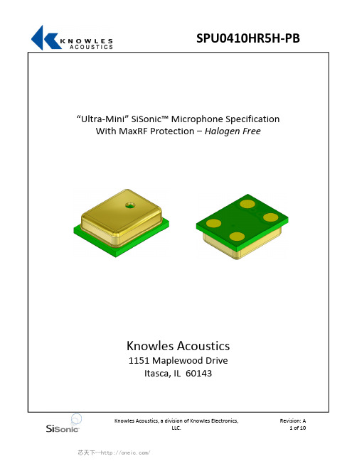
“Ultra‐Mini” SiSonic™ Microphone Specification With MaxRF Protection –Halogen FreeKnowles Acoustics1151 Maplewood DriveItasca, IL 601431. DESCRIPTION AND APPLICATION1.1 Description“Ultra Mini” Surface Mount Silicon Microphone with Maximum RF Protection –Halogen Free 1.2 ApplicationHand held consumer electronics2. PART MARKINGIdentification Number ConventionS 1 2 34 5 6 7S: Manufacturing Location“S” –Knowles Electronics SuzhouSuzhou, China“No Alpha Character” –Knowles Electronics ItascaItasca, IL USA 3“E” –Engineering Samples Digits 1 –7: Job Identification Number3.TEMPERATURE RANGE 3.1 Operating Temperature Range: ‐40°C to +100°C 3.2 Storage Temperature Range: ‐40°C to +100°C4. ACOUSTIC & ELECTRICAL SPECIFICATIONSSymbol ConditionLimitsUnit Min.Nom.Max.Directivity Omni‐directionalSensitivity S@ 1kHz (0dB=1V/Pa)‐45‐42‐39dB Output impedance Z OUT@ 1kHz (0dB=1V/Pa)‐‐‐‐‐‐300ΩCurrent Consumption I DSS across 1.5 to 3.6 volts‐‐‐‐‐‐250μA Signal to Noise Ratio S/N@ 1kHz (0dB=1V/Pa)‐‐‐59‐‐‐dB Supply Voltage Vs 1.5‐‐‐ 3.6VSensitivity Loss acrossVoltage Change in sensitivity over3.6v to 1.5vNo Change Across VoltageRangedBTHD At 100dB SPL, THD < 1%At 115dB SPL, THD < 10%dB5. FREQUENCY RESPONSE CURVE66. MECHANICAL SPECIFICATIONS7. RECOMMENDED CUSTOMER7LAND PATTERN8. RECOMMENDED SOLDER STENCIL PATTERNN/A9. RECOMMENDED INTERFACE CIRCUIT10. DETAIL 10PACKAGING11. SOLDER REFLOW PROFILE170–180°CSolder Melt Pre ‐heat 260°C230°Csec sec Stage Temperature ProfileTime (maximum)Pre ‐heat 170 ~ 180 C 120 sec.Solder Melt Above 230 C 100 sec.100 sec.120 sec.Notes:1.Do not pull a vacuum over the port hole of the microphone. Pulling avacuum over the port hole can damage the device.the reflow process.Board washing and cleaning Peak260 C maximum30 sec.2.Do not board wash afteragents can damage the device. Do not expose to ultrasonic processing or cleaning.3.Number of Reflow = recommend no more than 3 cycles.12ADDITIONAL NOTES (A)Shelf life: Twelve (12) months when devices are to be stored in factory supplied, unopened ESD moisture sensitive bag under maximum environmental conditions of 30ºC, 70% R.H. (B)MSL (moisture sensitivity level) Class 2a.12.13. RELIABILITY SPECIFICATIONSNote: After test conditions are performed, the sensitivity of the microphone shall not deviate more than 3dB from its initial value.Test DescriptionThermal Shock100 cycles of air‐air thermal shock from ‐40C to +125Cwith 15min soaks. (ICE 68‐2‐4)High Temperature St +105C environment for 1,000 hours. (IEC 68‐2‐2 Test Ba)StorageLow TemperatureStorage‐40C environment for 1,000 hours. (IEC 68‐2‐2 Test Aa)High Temperature Bias+105C environment while under bias for 1,000 hours. (IEC68‐2‐2 Test Ba)Low Temperature Bias‐40C environment while under bias for 1,000 hours. (IEC68‐2‐2 Test Aa)Temperature / Humidity Bias +85C/85% RH environment while under bias for 500 hours. (JESD22‐A101A‐B)Vibration4 cycles lasting 12 minutes from 20 to 2,000Hz in X, Y, andZ direction with a peak acceleration of 20g. (MIL 883E,Method 2007.2, A)Electrostatic Discharge3 discharges at +/‐8kV direct contact to the lid when unitis grounded (IEC 61000‐4‐2) and 3 discharges at +/‐2kVdirect contact to the I/O pins (MIL 883E, Method 3015.7) Reflow5 reflow cycles with peak temperature of 260C. Mechanical Shock3 pulses of 10,000g in the X, Y, and Z direction. (IEC 68‐2‐27, Test Ea)14. SPECIFICATION REVISIONSRevision Detailed Specification Changes Date X1Preliminary Specification Release06‐24‐2008A Specification 02172009release‐‐The information contained in this literature is based on our experience to date and is believed to be reliable and it is subject to change without notice.It is intended as a guide for use by persons having technical skill at their own discretion and risk.We do not guarantee favorable results or assume any liability in connection with its use.Dimensions contained herein are for reference purposes only.For specific dimensional requirements consult factory.This publication is not to be taken as a license to operate under,or recommendation to infringe any existing patents.This supersedes and voids all previous literature.。
美国AEMC公司高端和可移动数字弱电阻抗度计6550和6555产品说明书
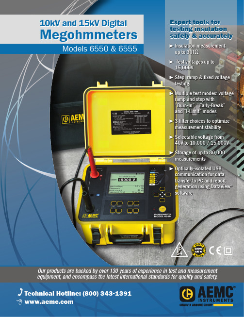
Technical Assistance (800) 343-1391 110kV and 15kV DigitalMegohmmetersModels 6550 & 6555► Insulation measurementup to 30T Ω► Test voltages up to 15,000V► Step, ramp & fixed voltagetesting► Multiple test modes: voltageramp and step with “Burn-In”, “Early-Break” and “I-Limit” modes► 3 filter choices to optimize measurement stability► Selectable voltage from40V to 10,000 / 15,000V ► Storage of up to 80,000 measurements► Optically-isolated USBcommunication for data transfer to PC and report generation using DataView ® softwareExpert tools for testing insulation safely & accuratelyIP 54Our products are backed by over 130 years of experience in test and measurement equipment, and encompass the latest international standards for quality and safety.Technical Hotline: (800) 343-13912 Technical Assistance (800) 343-1391Models 6550 & 6555HIGH-END & PORTABLEThe Megohmmeter Models 6550 and 6555 are high-end portable instruments intended for measuring a wide variety of electrical insulation resistance values oncables and devices operating at high voltage. They are packaged in a rugged case that is IP54 rated (cover closed). Test results and configuration information is provided on a graphical LCD screen, as well as exportable throughthe use of the DataView ® software provided. TheMegohmmeters can operate on battery or AC power while testing.These Megohmmeters contribute to the safety ofelectrical installations and equipment. Their operation is managed by microprocessors that acquire, process, display and store the measurements.The Model 6550 makes insulation measurements at voltages up to 10,000 V , the Model 6555 up to 15,000 V .Main Functions:• Detection and measurement of input voltage, frequency, and current prior to running a test.• Quantitative and qualitative insulation measurements.• Measurements at a fixed test voltage of 500, 1000, 2500, 5000, 10,000 or 15,000 V dc .• Measurements at an adjustable test voltagebetween 40 and 15,000 V dc preselected by the user prior to the test. Three preselected test voltages can be stored in the instrument and can be modified as needed prior to starting a test.IP 54• Ramp voltage measurements with a ramp from 40 to 10,000 V or 15,000 V , model dependent. Three ramp profiles can be stored in the instrument. Each ramp profile includes the starting and ending test voltage and the ramp time between the two.• Step voltage measurements with steps from 40 to 10,000 V or 15,000 V , model dependent.Three step voltage profiles can be stored in the instrument. Each contains up to 10 steps that include test voltage and duration.• Three test current choices: Burn-In, Early-Break and I-Limit provide qualitative analysis tools for detection breaks in insulation.• Quality ratio calculations for DAR, PI, and DD are calculated and displayed.• Temperature correction of the measured resistance to a reference temperature.• Capacitance measurement of the device tested.• Residual current measurement.Model 6555 checking insulation resistance on feed cables to a three-phase motor.Technical Assistance (800) 3►► SELECTABLE VOLTAGE FROM 40V TO 10kV / 15kV MODELSINSULATION TESTSTest VoltageAPPLICATIONS► Acceptance testing and preventive maintenance ► Test motors, cables, switchgears and wiring installations4 Technical Assistance (800) 343-1391CONTROL FEATURESFront Panel Features for Models 6550 & 6555Socket for connection to the ACpower and recharging of thebuilt-in batteriesmeasurementbuttonsUSB connector forcommunicationto a PC Seven position access to the fixed voltage, adjustable voltage,ramp and stepLarge, digital, backlit, Models 6550 and 6555 have the same front panel with differences in the display only .5Measurement Results Display AreaDisplay ofResultsTechnical Assistance (800) 5FUNCTIONSModels 6550 & 65556 Technical Assistance (800) 343-1391bargraphterminalsExample of display during measurement.resistanceresistance referred to the reference temperature.cursor Resistance versus time graph.This curve is useful primarily in the case of a measurement in V-RAMP mode.When Timed Run (test with programmed duration) or Timed Run + DD is selected, the duration of the measurement (m:s) can be set.The number of measurements that can be recorded depends on the number of samples stored for each measurement.quality ofof memory white).indicated.T est with programmed durationExample of display before measurement.FUNCTIONAL DISPLAYSSOFTWARE & ANALYSIS SCREENSEasy identification of all stored test results.Real-time display of measurement results.Step voltage set up screen.Technical Assistance (800) 7ORDERING INFORMATION M egohmmeter Model 6550 Ramp, StepV , Variable, Auto DAR/PI/DD, USB w/DataView Megohmmeter Model 6555 Ramp, StepV , Variable, Auto DAR/PI/DD, USB w/DataView AEMC ® Instruments • 15 Faraday Dr. • Dover, NH 03820 USA • (800) 343-1391•Fax(603)742-2346•E-mail:**************Export Department: +1 (603) 749-6434 x520 • Fax +1(603)742-2346•E-mail:***************© Chauvin Arnoux ®, Inc. d.b.a. AEMC ®Instruments Call the AEMC ® Instruments Technical Assistance Hotline for immediate consultation with an applications engineer: (800) 343-1391950.BR-6550-6555_0323 • Printed in the USA M u lt i-p u r p o s e C la m p -O n M e t e r s ca o tl in M E G O H MM E T E R SFo r a ll of y ou r I ns ul at io n Te st in g ne ed s...ch ni ca l H o tl in e: (800) 343-1391.a em c.co mP O W E R Q U A L I T Y Fo rA ll Y ou r Po w er Q ua li ty N ee ds ...Te 43-1391w w w ( Fo r a ll of yo ur G ro un d In te gr ity T es tin g ne ed s...G R O U N D R E S IS TA N C E T E S TE R S Te ch ni ca l H ot lin e: (800) 343-1391w w w .a em c.co mTEST & MEA SUREM ENT INSTR UMEN TSVOLUM E 23WWW.AEM TECHNICA L HOTLINE : (800) 343-1391Family of ProductsTo learn more, visit 。
XL4005演示板说明书
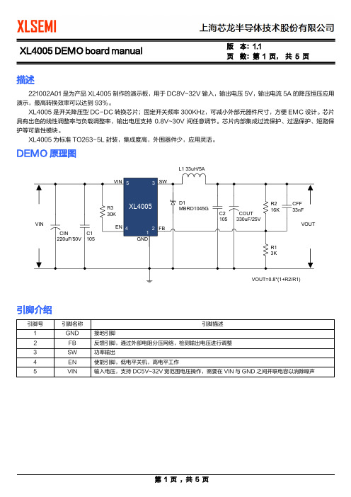
页数:第1 页,共5 页描述221002A01是为产品XL4005制作的演示板,用于DC8V~32V输入,输出电压5V,输出电流5A的降压恒压应用演示,最高转换效率可以达到93%。
XL4005是开关降压型DC-DC转换芯片;固定开关频率300KHz,可减小外部元器件尺寸,方便EMC设计。
芯片具有出色的线性调整率与负载调整率,输出电压支持0.8V~30V间任意调节。
芯片内部集成过流保护、过温保护、短路保护等可靠性模块。
XL4005为标准TO263-5L封装,集成度高,外围器件少,应用灵活。
DEMO原理图引脚介绍页数:第2 页,共5 页物料清单性能测试转换效率页 数:第 3 页, 共 5 页转换效率: 线性调整率与负载调整率:Efficiency VS Load currentE f f i c i e n c y (%)Load current(A)Output voltage VS Output currentO u t p u t v o l t a g e (V )Output current(A)页 数:第 4 页, 共 5 页DEMO 实物图PCB 布局顶层 底层页数:第5 页,共5 页应用信息输入电容选择在连续模式中,转换器的输入电流是一组占空比约为VOUT/VIN的方波。
为了防止大的瞬态电压,必须采用针对最大RMS电流要求而选择低ESR(等效串联电阻)输入电容器。
对于大多数的应用,1个10uF的输入电容器就足够了, 它的放置位置尽可能靠近XL4005的位置上。
最大RMS电容器电流由下式给出:IRMS≈IMAX*√VOUT(VIN-VOUT)VIN其中,最大平均输出电流IMAX等于峰值电流与1/2峰值纹波电流之差,即IMAX=ILIM-△IL/2。
在未使用陶瓷电容器时,还建议在输入电容上增加一个0.1uF至1uF的陶瓷电容器以进行高频去耦。
输出电容选择在输出端应选择低ESR电容以减小输出纹波电压,一般来说,一旦电容ESR得到满足,电容就足以满足需求。
型号1N4004(MULTICOMP)中文数据手册「EasyDatasheet」
pF °C/W
°C
典型正向特性
安培
平均正向整流电流 环境温度(℃)
瞬时正向电流( A) 正向电压( V)
第2页
07/05/10 V1.1
芯片中文手册,看全文,戳
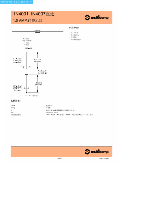
1N4001 1N4007直通
1.0 AMP.硅整流器
额 定 值 和 特 性 曲 线 ( 1N4001)
最大非重复正向浪涌电流
第3页
07/05/10 V1.1
第1页
05/05/10 V1.1
芯片中文手册,看全文,戳
1N4001 1N4007直通
1.0 AMP.硅整流器
最大额定值和电气特性:
评分在25°C环境温度,除非另有规定. 单相,半波,60赫兹,电阻或电感性负载. 对于容性负载,减免电流20%.
型号数量
最大经常峰值反向电压
最大RMS电压
典型结电容
峰值正向浪涌电流( A) 循环次数在 60Hz
典型反向特性
µ
瞬时反向电流( μA)
额定峰值反向电压百分比(%)
结电容( pF) 反向电压( V)
Disclaimer This data sheet and its contents (the "Information") belong to the Premier Farnell Group (the "Group") or are licensed to it. No licence is granted for the use of it other than for information purposes in connection with the products to which it relates. No licence of any intellectual property rights is granted. The Information is subject to change without notice and replaces all data sheets previously supplied. The Information supplied is believed to be accurate but the Group assumes no responsibility for its accuracy or completeness, any error in or omission from it or for any use made of it. Users of this data sheet should check for themselves the Information and the suitability of the products for their purpose and not make any assumptions based on information included or omitted. Liability for loss or damage resulting from any reliance on the Information or use of it (including liability resulting from negligence or where the Group was aware of the possibility of such loss or damage arising) is excluded. This will not operate to limit or restrict the Group's liability for death or personal injury resulting from its negligence. SPC Multicomp is the registered trademark of the Group. © Premier Farnell plc 2010.
XL3005规格书(中文版)
打印名称 XL3005E1
封装方式 TO263-5L
包装类型 800 只每卷
XLSEMI 无铅产品,产品型号带有“E1”后缀的符合 RoHS 标准。
绝对最大额定值(注 1)
参数 输入电压 输出开关引脚电压 电流采样引脚电压 功耗 热阻 (TO263-5L) (结到环境,无外部散热片) 最大结温 操作结温 贮存温度范围 引脚温度(焊接10秒) ESD (人体模型)
85.0
82.5
VIN=8V,IOUT=1540mA
80.0 77.5
VIN=12V,IOUT=1540mA VIN=24V,IOUT=1540mA VIN=36V,IOUT=1540mA
75.0
72.5
70.0
67.5
65.0
62.5
60.0
1
2
3
4
5
6
7
8
9
10
LED String(N*5W)
图20. XL3005系统效率曲线
220KHz 36V 5A开关电流降压型LED恒流驱动器
Datasheet
XL3005
特点
n 8V到36V宽输入电压范围 n 0.21V输出电流采样电压 n 最大占空比100% n 最小压差0.3V n 固定220KHz开关频率 n 最大5A开关电流 n 内置功率MOS n 出色的线性与负载调整率 n 内置频率补偿功能 n 内置输出短路保护功能 n 内置热关断功能 n 内置电流限制功能 n TO263-5L封装
Recommend output voltage safe work range
30
28
26
IOUT=2000mA
PBLS4003D,115;中文规格书,Datasheet资料
Symbol Parameter
Conditions
Min
TR1; PNP low VCEsat transistor
VCBO
collector-base voltage
open emitter
-
VCEO
collector-emitter voltage
open base
-
VEBO
emitter-base voltage
Version SOT457
4. Marking
Table 4. Marking codes Type number PBLS4003D
Marking code R3
5. Limiting values
Table 5. Limiting values In accordance with the Absolute Maximum Rating System (IEC 60134).
1.3 Applications
I Supply line switches I Battery charger switches I High-side switches for LEDs, drivers and backlights I Portable equipment
1.4 Quick reference data
PBLS4003D
40 V PNP BISS loadswitch
Rev. 03 — 5 January 2009
Product data sheet
1. Product profile
1.1 General description
PNP low VCEsat Breakthrough In Small Signal (BISS) transistor and NPN ResistorEquipped Transistor (RET) in a SOT457 (SC-74) small Surface-Mounted Device (SMD) plastic package.
SPU0410LR5H-QB, 规格书,Datasheet 资料
"W"
0.612 0.722 (2X) 1 1.224 "AP" 0.610 2 0.562 (2X)
1 "L" 3.330
2.636 2.101 (3X)
2.540
R0.254
0.634 (2X) 0.485
3 1.015 2.031
2.00±0.05 1.75±0.10 12.0±0.3 4.00 8.00±0.10
0.30±0.05 1.30±0.10
A
5.50±0.05 3.40±0.10 4.16±0.10 PIN #1 A
+0.1 1.5 0.0 +0.1 1.5 0.0
COMPONENT ORIENTATION
Note: Dimensions are in milimeters unless otherwise specified.
Revision: C Release Level: ACTIVE Sheet 2 of 11
芯天下--/
SPU0410LR5H-QB
Knowles Acoustics, a division of Knowles Electronics, LLC.
Revision: C Release Level: ACTIVE Sheet 3 of 11
spu0410lr5hqb规格书datasheet资料
SPU0410LR5H-QB
Zero Height "Ultra-Mini" SiSonic Microphone Specification With MaxRF Protection - Halogen Free
jw1965o芯片规格书
jw1965o芯片规格书全文共四篇示例,供读者参考第一篇示例:jw1965o芯片是一款高性能的集成电路芯片,具有先进的制造工艺和优秀的性能特点。
本文将介绍jw1965o芯片的规格书,包括其技术参数、功能特点和应用领域等方面的详细信息。
一、技术参数1. 芯片型号:jw1965o2. 封装形式:QFN封装3. 工作电压:1.8V-3.6V4. 工作频率:主频0-500MHz5. 存储容量:256KB Flash,64KB RAM6. 通信接口:UART、SPI、I2C7. 电源管理:支持多种低功耗模式8. 温度范围:-40℃-85℃9. 尺寸:5mm*5mm二、功能特点1. 高性能:jw1965o芯片采用先进的CMOS工艺,具有较高的工作频率和处理性能,适用于高要求的应用场景。
2. 低功耗:芯片内置多种低功耗模式,能够有效降低功耗,延长电池使用时间。
3. 多种通信接口:jw1965o芯片支持UART、SPI、I2C等多种通信接口,能够满足不同应用的通信需求。
4. 强大的存储容量:芯片内置256KB Flash和64KB RAM,可以满足各种数据存储和处理需求。
5. 多种应用领域:jw1965o芯片广泛应用于物联网、智能家居、工业控制等领域,可提供稳定可靠的嵌入式系统解决方案。
三、应用领域1. 物联网设备:jw1965o芯片具有丰富的通信接口和强大的处理能力,适用于各类物联网设备的数据处理和通信传输。
2. 智能家居:芯片低功耗、高性能的特点,使其成为智能家居设备的理想选择,可以实现远程控制、数据传输等功能。
3. 工业控制:jw1965o芯片在工业控制领域有着广泛的应用,可提供稳定可靠的控制系统解决方案,应用于工业自动化、机器人等领域。
第二篇示例:jw1965o 芯片是一款高性能、低功耗的芯片,广泛应用于各种智能设备中,比如智能手机、智能家居、智能穿戴等。
该芯片采用先进的制程工艺和架构设计,具有强大的计算能力和较低的能耗,能够满足用户对于高性能和长续航的需求。
- 1、下载文档前请自行甄别文档内容的完整性,平台不提供额外的编辑、内容补充、找答案等附加服务。
- 2、"仅部分预览"的文档,不可在线预览部分如存在完整性等问题,可反馈申请退款(可完整预览的文档不适用该条件!)。
- 3、如文档侵犯您的权益,请联系客服反馈,我们会尽快为您处理(人工客服工作时间:9:00-18:30)。
301 Washington St, Cannon Falls MN 55009 · (507) 263-3766 Fax (507) 263-5085 · w
Thermal Products · Membrane Switches · Electronic Components · Touch Screens 7” LCD Monitor with Projected Capacitive Touch Solution
Bergquist presen ts you the projected capacitive touch solution covering a 7” TFT touch monitor in a metal enclosure attached to
Bergquist’s projected capacitive touch panel, PenMount 1200 projected capacitive touch control board with fine-tuned firmware. This touch monitor module connects to the computers directly by USB port. On Windows 7 O.S. it accesses the Windows 7 inbox driver to perform using single and dual –touch inputs. A utility program is included form customizing the touch sensitivity and various touch performances.
Touch Monitor Features
∙ 7” TFT LCD monitor with projected capacitive touch solution
∙ Supporting single and dual touch
∙ Bergquist 7” projected capacitive touch panel
∙ PenMount 1200 projected capacitive touch control board
∙ VGA interface to communicate with the host computer for LCD display
∙ USB interface to communicate with the host computer for touch controller
LCD Monitor Specification
∙ LCD Diagonal Size: 7” TFT LCD
∙ LCD Resolution: 800x480
∙ LCD Dot Pitch: 0.0635 (W) x 0.1905 (H) mm
∙ LCD Active Area 152.4 (W) x 91.44 (H) mm
∙ LCD Dimensions: 165 (W) x 104 (H) x 6.5 (D) mm
∙ Interface: TTL Digital Display Board
∙ Backlight Power Consumption: 2.5W (Typ.)
∙ LCD Panel Power Consumption : 0.825W (Typ)
∙ Interface to Main System: VGA Port
∙ Power Cord Included
∙ Weight: 830g (including touch panel and control board)
∙ Dimensions: 101 (W) x 127 (H) x 38 (D) mm
∙ Operating Temperature: -10˚C to +60˚C
∙ Storage Temperature: -20˚C to +70˚C
Bergquist 400552 Projected Capacitive Touch Panel Specification
∙Technology: Projected Capacitive
∙Measurement Resolution: 1024
∙Response Time: <20ms
∙Touch Function: Single and Dual Touch
∙Light Transmission: >88%
∙Haze: <3%
∙Sensor Thickness: 1.75±0.2mm
∙Top Glass Thickness: 1.1mm
∙Glass Hardness: Mohs 5
∙Tail Design: FPC Tail
∙Activation Force: Forceless
∙Operating Temperature: -20˚C to +70˚C
∙Storage Temperature: -40˚C to +80˚C
∙Humidity: 10% to 90% RH
∙Touch Panel Dimensions: 166.4 (W) x 108.4 (H) x 1.75 (D) mm
PenMount 1200 Projected Capacitive Touch Controller Specification
∙Power Consumption: DC +5V, Max 50mA, Typ 25-40mA
∙Interface: USB 2.0 compatible, full speed
∙Resolution: 1024x1024
∙Accuracy: <1mm
∙Single Touch: 200 points/sec
∙Dual Touch: 100 points/sec
∙Response Time: Max 40ms
∙Operating Temperature: -25˚C to +80˚C
∙Storage Temperature: -40˚C to +90˚C
∙Relative Humidity: 90% RH at 40˚C (non-condensing)
∙Control Board Dimensions: 40 x 60mm
∙USB Cable Included
∙RoHS Compliant
5300 Edina Industrial Boulevard Edina, MN 55439 · (800) 347-4572 Fax (612) 835-0430 · w Thermal Products · Membrane Switches · Electronic Components · Touch Screens。