实验三 8位乘法器的设计
实验三 8位算术逻辑运算实验

实验一 讲解结束 实验开始
二、实验环境
硬件:DVCC-C8JH 实验箱。
三、实验内容
1、算术逻辑运算功能发生器 74LS181(U31、U32) 以手动方式用二进制开关S3、S2、S1、S0、CN、M来 模拟74LS181(U31、U32)的功能控制信号S3、S2、 S1、S0、CN、M ; 2、其它电平控制信号以手动方式用二进制开关 LDDR1、LDDR2、ALUB、SWB来模拟 3、通过跳线器切换,其中ALUB`、SWB`为低电平 有效,LDDR1、LDDR2为高电平有效。 另有信号T4为脉冲信号,在手动方式下进行实验时, 只需将跳线器J23上T4与手动脉冲发生开关的输出端 SD相连,按动手动脉冲开关,即可获得实验所需的单
⑴ 连接线路,仔细查线无误后,接通电源。
⑵ 用二进制数码开关KD0~KD7向DR1和DR2寄存器置数。方法:关闭 ALU输出三态门(ALUB`=1),开启输入三态门(SWB`=0),输入脉冲 T4按手动脉冲发生按钮产生。
六、 实 验 数 据
七、思考题
1、在向DR1和DR2寄存器置数时S3、S2、S1、 S0、M、Cn如何设置? 2、DR1置数完成后,如果不关闭控制端, LDDR1会怎样? 3、为什么在读取74LS181的输出结果时要打开 输出三态门的控制端ALUB’ ?
四、 实 验 线 路 连 接
四、实验线路连接(续)
本实验用到4个主要模块:⑴低8位运算器模块,⑵数 据输入并显示模块,⑶数据总线显示模块,⑷功 能开关模块(借用微地址输入模块)。 根据实验原理详细接线如下: ⑴ ALUBUS连EXJ3; ⑵ ALUO1连BUS1; ⑶ SJ2连UJ2; ⑷ 跳线器J23上T4连SD; ⑸ LDDR1、LDDR2、ALUB、SWB四个跳线器拨在左 边(手动方式); ⑹ AR跳线器拨在左边,同时开关AR拨在“1”电平。
移位相加8位乘法器的设计
EDA技术课程大作业设计题目:移位相加8位乘法器的设计院系:电子信息与电气工程学院学生姓名:学号:200902070017专业班级:09电子信息工程专升本2010年12月3日移位相加8位乘法器的设计1.设计背景和设计方案1.1设计背景EDA技术(即Electronic Design Automation技术)就是依赖强大的计算机,在EDA工具软件平台上,对以硬件描述语言HDL(Hardware Ddscription Langurage)为系统逻辑描述手段完成的设计文件,自动地完成逻辑编译、化简、分割、综合、布局布线以及逻辑优化和仿真测试,直至实现既定的电子线路系统功能。
它在硬件实现方面融合了大规模集成电路制造技术、IC版图设计、ASIC 测试和封装、FPGA(Gield Peogrammable Gate Array)/CPLD(Complex Programmable Logic Device)编程下载和自动测试等技术;在计算机辅助工程方面融合了计算机辅助设计(CAD),计算机辅助制造(CAM),计算机辅助测试(CAT),计算机辅助工程(CAE)技术以及多种计算机语言的设计概念;而在现代电子学方面则容纳了更多的内容,如电子线路设计理论、数字信号处理技术、数字系统建模和优化技术及长线技术理论等。
本文介绍设计一个两个5位数相乘的乘法器。
用发光二极管显示输入数值,用7段显示器显示十进制结果。
乘数和被乘数分两次输入。
在输入乘数和被乘数时,要求显示十进制输入数据。
输入显示和计算结果显示,采用分时显示方式进行,可参见计算器的显示功能1.2设计方案此设计是由八位加法器构成的以时序逻辑方式设计的八位乘法器,它的核心器件是八位加法器,所以关键是设计好八位加法器。
方案一:八位直接宽位加法器,它的速度较快,但十分耗费硬件资源,对于工业化设计是不合理的。
方案二:由两个四位加法器组合八位加法器,其中四位加法器是四位二进制并行加法器,它的原理简单,资源利用率和进位速度方面都比较好。
应用移位相加原理设计8位乘法器
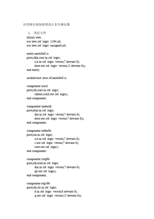
应用移位相加原理设计8位乘法器1.顶层文件library ieee;use ieee.std_logic_1164.all;use ieee.std_logic_unsigned.all;entity multi8x8 isport(clkk,start:in std_logic;a,b:in std_logic_vector(7 downto 0);dout:out std_logic_vector(15 downto 0));end entity;architecture struc of multi8x8 iscomponent arictlport(clk,start:in std_logic;clkout,rstall:out std_logic);end component;component andarithport(abin:in std_logic;din:in std_logic_vector(7 downto 0);dout:out std_logic_vector(7 downto 0));end component;component adder8bport(cin:in std_logic;a,b:in std_logic_vector(7 downto 0);s:out std_logic_vector(7 downto 0);cout:out std_logic);end component;component sreg8bport(clk,load:in std_logic;din:in std_logic_vector(7 downto 0);qb:out std_logic);end component;component reg16bport(clk,clr:in std_logic;d:in std_logic_vector(8 downto 0);q:out std_logic_vector(15 downto 0));end component;signal gndint,intclk,rstall,newstart,qb:std_logic;signal andsd:std_logic_vector(7 downto 0);signal dtbin:std_logic_vector(8 downto 0);signal dtbout:std_logic_vector(15 downto 0);begindout<=dtbout;gndint<='0';process(clkk,start)beginif(start='1')thennewstart<='1';else if(clkk='0')thennewstart<='0';end if;end if;end process;u1:arictl port map(clk=>clkk,start=>newstart,clkout=>intclk,rstall=>rstall);u2:sreg8b port map(clk=>intclk,load=>rstall,din=>b,qb=>qb);u3:andarith port map(abin=>qb,din=>a,dout=>andsd);u4:adder8b port map(cin=>gndint,a=>dtbout(15 downto 8),b=>andsd,s=>dtbin(7 downto 0),cout=>dtbin(8));u5:reg16b port map(clk=>intclk,clr=>rstall,d=>dtbin,q=>dtbout);end architecture;2.各部件1)arictl—控制元件library ieee;use ieee.std_logic_1164.all;use ieee.std_logic_unsigned.all;entity arictl isport(clk,start:in std_logic;clkout,rstall:out std_logic);end entity;architecture bhv of arictl issignal cnt4b:std_logic_vector(3 downto 0);beginprocess(clk,start)beginrstall<=start;if(start='1')thencnt4b<="0000";else if(clk'event and clk='1')thenif(cnt4b<8)thencnt4b<=cnt4b+1;end if;end if;end if;end process;process(clk,cnt4b,start)beginif(start='0')thenif(cnt4b<8)thenclkout<=clk;elseclkout<='0';end if;elseclkout<=clk;end if;end process;end architecture;2)sreg8b—8位移位寄存器元件library ieee;use ieee.std_logic_1164.all;entity sreg8b isport(clk,load:in std_logic;din: in std_logic_vector(7 downto 0);qb:out std_logic );end sreg8b;architecture behav of sreg8b issignal reg8 : std_logic_vector(7 downto 0); beginprocess(clk,load)beginif clk'event and clk = '1' thenif load ='1' then reg8<=din;else reg8(6 downto 0)<=reg8(7 downto 1);end if;end if;end process;qb<=reg8(0);end behav;3)andarith—一位乘法元件library ieee;use ieee.std_logic_1164.all;entity andarith isport( abin: in std_logic;din: in std_logic_vector(7 downto 0);dout : out std_logic_vector(7 downto 0) );end andarith;architecture behav of andarith isbeginprocess(abin,din)beginfor i in 0 to 7 loopdout(i)<=din(i) and abin;end loop;end process;end behav;4)adder8b—8位加法元件library ieee;use ieee.std_logic_1164.all;use ieee.std_logic_unsigned.all;entity adder8b isport (cin : in std_logic;a,b : in std_logic_vector(7 downto 0);s : out std_logic_vector(7 downto 0);cout : out std_logic );end adder8b;architecture behav of adder8b issignal sint,aa,bb : std_logic_vector(8 downto 0); beginaa<='0'& a;bb<='0'& b;sint<=aa+bb+cin;s<=sint(7 downto 0);cout<=sint(8);end behav;5)reg16b—16位移位寄存器元件library ieee;use ieee.std_logic_1164.all;use ieee.std_logic_unsigned.all;entity reg16b is --16 bit shift register port(clk,clr:in std_logic;d:in std_logic_vector(8 downto 0);q:out std_logic_vector(15 downto 0));end entity;architecture bhv of reg16b issignal r16s:std_logic_vector(15 downto 0);beginprocess(clk,clr)beginif(clr='1') thenr16s<="0000000000000000" ;else if(clk'event and clk='1')thenr16s(6 downto 0)<=r16s(7 downto 1);r16s(15 downto 7)<=d;end if;end if;end process;q<=r16s;end architecture;。
中山学院EDA综合实验报告-8位硬件乘法器设计

在实验老师的指导下,我圆满完成了实验任务,有了不少收获,其中了解到了移位相加原理构成乘法器与用组合逻辑电路直接设计的同样功能的电路优势,并且在加深了如何通过VerilogHDL生成原理图器件并进行相应仿真,最后学习了应用移位相加原理设计8位乘法器。
3、ADDER8BT的仿真图及分析
如图所示,红色剪头表示8+11=19,绿色剪头表示8+9=17,紫色剪头表示8+9+1=18,这说明S=A+B+CIN。
4、完整乘法器的仿真图及分析
如图所示,红色剪头表示外部按键START按下(给SREG8BT的LOAD高电平)时给ARIEND一个高电平输出,绿色剪头处的Q为31104,而31104<<1结果为0xF300,此处最高位为0xF3,即相乘的结果为0xF3,这里表示B的数值0xF3乘以A的数值0xC8第4位再加上前3位的结果,因为前3位相乘后的结果为0,因此这里相乘的结果为0xF3,紫色剪头也是同理。
如图所示,在第一个2,此时输出Q=1536,其二进制表示为0000 0110 0000 0000,由VerilogHDL代码可知R16S[6:0]<=R16S[7:1]即R16S[6:0] = 0,R16S[15:7] = 12,此结果与Q输出结果一致绿色剪头与紫色剪头也是同理。
学生实验报告
系别
电子信息学院
课程名称
《EDA综合实验》
班级
实验名称
8位硬件乘法器设计
姓名
实验时间
学号
指导教师
成绩
批改时间
报告内容
一、实验目的和任务
1、学习应用移位相加原理设计8位乘法器。
2、了解移位相加原理构成乘法器与用组合逻辑电路直接设计的同样功能的
8位乘法器设计范文
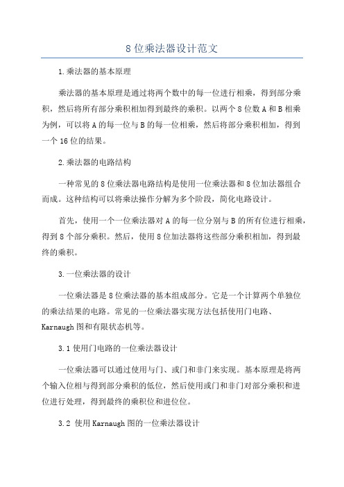
8位乘法器设计范文1.乘法器的基本原理乘法器的基本原理是通过将两个数中的每一位进行相乘,得到部分乘积,然后将所有部分乘积相加得到最终的乘积。
以两个8位数A和B相乘为例,可以将A的每一位与B的每一位相乘,然后将部分乘积相加,得到一个16位的结果。
2.乘法器的电路结构一种常见的8位乘法器电路结构是使用一位乘法器和8位加法器组合而成。
这种结构可以将乘法操作分解为多个阶段,简化电路设计。
首先,使用一个一位乘法器对A的每一位分别与B的所有位进行相乘,得到8个部分乘积。
然后,使用8位加法器将这些部分乘积相加,得到最终的乘积。
3.一位乘法器的设计一位乘法器是8位乘法器的基本组成部分。
它是一个计算两个单独位的乘法结果的电路。
常见的一位乘法器实现方法包括使用门电路、Karnaugh图和有限状态机等。
3.1使用门电路的一位乘法器设计一位乘法器可以通过使用与门、或门和非门来实现。
基本原理是将两个输入位相与得到部分乘积的低位,然后使用或门和非门对部分乘积和进位进行处理,得到最终的乘积位和进位位。
3.2 使用Karnaugh图的一位乘法器设计Karnaugh图是一种按照二进制输入和输出函数绘制的图表。
它可以帮助分析和简化布尔代数函数。
使用Karnaugh图可以快速绘制并简化一位乘法器的逻辑电路。
3.3使用有限状态机的一位乘法器设计有限状态机是一种具有有限个状态和状态转移规则的模型。
可以使用有限状态机模型来描述和实现一位乘法器的行为。
这种设计方法可以更好地描述一位乘法器的状态转移关系,但也需要更复杂的控制电路。
4.8位乘法器的实现使用一位乘法器的设计方法,可以将乘法器分为两个阶段:部分乘积生成和部分乘积相加。
首先,使用8个一位乘法器对A的每一位与B的每一位进行相乘,得到8个部分乘积。
然后,使用8位加法器将这些部分乘积相加,得到最终的乘积。
这个设计方法的优点是每个一位乘法器可以独立并行地进行计算,提高了计算效率。
而且,部分乘积生成和部分乘积相加可以分别设计和优化,使得整个乘法器的电路结构更清晰。
ASIC系统设计实验报告八位乘法器
八位乘法器的设计汪明 2080130204 信号与信息处理 乘法是算术运算中经常用到的一个运算单元,所以在算法实现中会经常用到乘法。
由于乘法器具有一定的复杂性,考虑到面积等因素,很多传统的处理器中都不包含乘法器单元,乘法则是通过算法换算成加法和移位在处理器中进行实现,针对这些处理器编写程序的时候应尽量少的应用乘法运算。
随着DSP 技术的逐步发展,目前大多数高性能的处理器中都包含了乘法器运算单元,但仍有很多小型的控制型处理器不包含这一单元,所以设计面积小、速度快、性能稳定的乘法器模块仍然很有意义。
本实验的目的是选用一种设计方案设计一个八位乘法器,利用XINLINX ISE 软件进行VHDL 程序的编写,然后对程序进行仿真验证,并对所设计的乘法器进行评价。
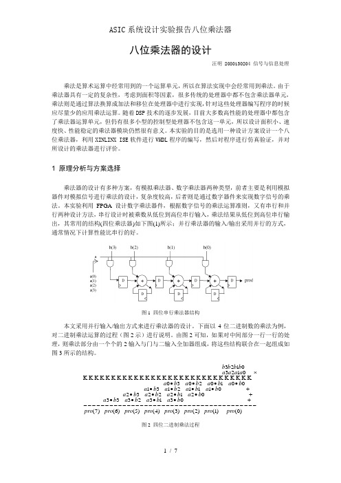
1 原理分析与方案选择乘法器的设计有多种方案,有模拟乘法器、数字乘法器两种类型,前者主要是利用模拟器件对模拟信号进行乘法的设计,复杂度较高,后者则是通过数字器件来实现数字信号的乘法。
本实验利用FPGA 设计数字乘法器件,根据数字信号的乘法运算准则,又有串行和并行两种设计方法,串行设计时被乘数从低位到高位串行输入,乘法结果从低位到高位串行输出,其常用的结构(四位乘法器)如下图(1)所示;并行乘法器的输入/输出采用并行的方式,通常情况下计算性能比串行的好。
图1 四位串行乘法器结构本文采用并行输入/输出方式来进行乘法器的设计。
下面以4位二进制数的乘法为例,对二进制乘法运算的过程(图2示)进行说明。
由图2可知,如果对中间部分一行一行的处理,则乘法部分由一个个的2输入与门与二输入全加器组成,将这些结构联合在一起组成如图3所示的结构。
)0()1()2()3()4()5()6()7(0313233302122232011121310010203001230123pro pro pro pro pro pro pro pro b a b a b a b a b a b a b a b a b a b a b a b a b a b a b a b a a a a a b b b b ----------------------------------------+••••+••••+••••••••⨯K K K K K K K K K K K K K K K K K K K K K K K K K K K K K K 图2 四位二进制乘法过程图3 四位二进制乘法结构图从图3可以看出,上述结构中顶层、底层、中间层分别采用不同的结构,而且中间层的三个层结构完全相同。
实验三 8位乘法器的设计
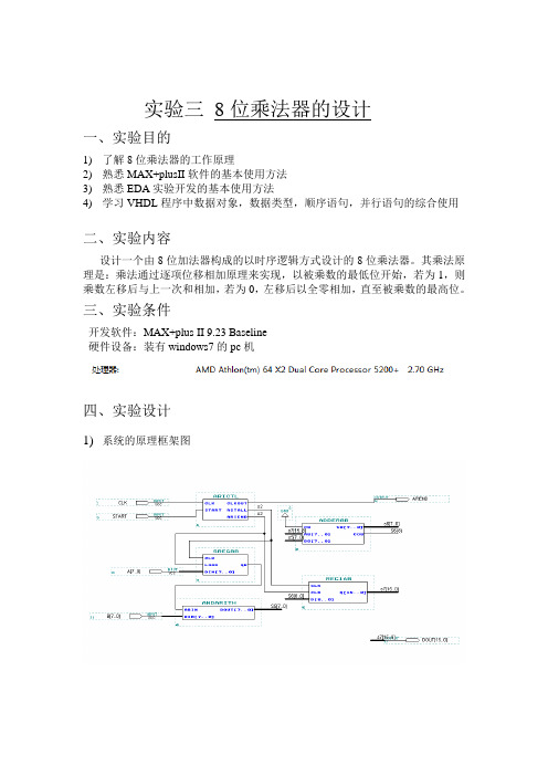
实验三8位乘法器的设计一、实验目的1)了解8位乘法器的工作原理2)熟悉MAX+plusII软件的基本使用方法3)熟悉EDA实验开发的基本使用方法4)学习VHDL程序中数据对象,数据类型,顺序语句,并行语句的综合使用二、实验内容设计一个由8位加法器构成的以时序逻辑方式设计的8位乘法器。
其乘法原理是:乘法通过逐项位移相加原理来实现,以被乘数的最低位开始,若为1,则乘数左移后与上一次和相加,若为0,左移后以全零相加,直至被乘数的最高位。
三、实验条件开发软件:MAX+plus II 9.23 Baseline硬件设备:装有windows7的pc机四、实验设计1)系统的原理框架图2)VHDL源程序andarith.vhd源代码library ieee;use ieee.std_logic_1164.all;entity andarith isport(abin:in std_logic;din:in std_logic_vector(7 downto 0); dout: out std_logic_vector(7 downto 0)); end entity andarith;architecture art of andarith isbeginprocess(abin, din)isbeginfor i in 0 to 7 loopdout(i)<=din(i)and abin;end loop;end process;end architecture art;arictl.vhd源代码library ieee;use ieee.std_logic_1164.all;use ieee.std_logic_unsigned.all;entity arictl isport(clk:in std_logic; start: in std_logic; clkout:out std_logic; rstall: out std_logic; ariend: out std_logic);end entity arictl;architecture art of arictl issignal cnt4b:std_logic_vector(3 downto 0); beginrstall<=start;process(clk, start)isbeginif start='1' then cnt4b<="0000";elsif clk'event and clk='1'thenif cnt4b<8 thencnt4b<=cnt4b+1;end if;end if;end process;process (clk,cnt4b,start)isbeginif start='0'thenif cnt4b<8 thenclkout<=clk; ariend<='0';else clkout<='0'; ariend<='1';end if;else clkout<=clk; ariend<='0';end if;end process;end architecture art;sreg8b.vhdlibrary ieee;use ieee.std_logic_1164.all;entity sreg8b isport (clk: in std_logic;load: in std_logic;din: std_logic_vector(7 downto 0);qb: out std_logic);end entity sreg8b;architecture art of sreg8b issignal reg8:std_logic_vector(7 downto 0); beginprocess(clk, load)isbeginif clk'event and clk='1'thenif load='1'then reg8<=din;else reg8(6 downto 0)<=reg8(7 downto 1); end if;end if;end process;qb<=reg8(0);end architecture art;reg16b.vhdlibrary ieee;use ieee.std_logic_1164.all;entity reg16b isport(clk: in std_logic;clr: in std_logic;d: in std_logic_vector(8 downto 0);q: out std_logic_vector(15 downto 0));end entity reg16b;architecture art of reg16b issignal r16s: std_logic_vector(15 downto 0);beginprocess(clk,clr)isbeginif clr='1'then r16s<="0000000000000000";elsif clk'event and clk='1'thenr16s(6 downto 0)<=r16s(7 downto 1);r16s (15 downto 7)<=d;end if ;end process;q<= r16s ;end architecture art;Adder8b.vhd源代码library ieee;use ieee.std_logic_1164.all;use ieee.std_logic_unsigned.all;entity adder8b isport( c8:in std_logic;a8:in std_logic_vector(7 downto 0);b8: in std_logic_vector(7 downto 0);s8: out std_logic_vector(7 downto 0);co8: out std_logic);end entity adder8b ;architecture art of adder8b iscomponent adder4b isport(c4: in std_logic;a4: in std_logic_vector(3 downto 0);b4: in std_logic_vector(3 downto 0);s4: out std_logic_vector(3 downto 0);co4: out std_logic);end component adder4b;signal sc:std_logic;beginu1:adder4bport map(c4=>c8,a4=>a8(3 downto 0),b4=>b8(3 downto 0), s4=>s8(3 downto 0),co4=> sc);u2:adder4bport map(c4=>sc, a4=>a8(7 downto 4),b4=>b8(7 downto 4),s4=>s8(7 downto 4),co4=>co8);end architecture art;multi8x8.vhdlibrary ieee;use ieee.std_logic_1164.all;entity multi8x8 isport(clk: in std_logic;start: in std_logic;a: in std_logic_vector(7 downto 0);b: in std_logic_vector(7 downto 0);ariend: out std_logic;dout: out std_logic_vector(15 downto 0));end entity multi8x8;architecture art of multi8x8 iscomponent arictl isport(clk:in std_logic;start: in std_logic;clkout:out std_logic;rstall:out std_logic;ariend:out std_logic);end component arictl;component andarith isport(abin: in std_Logic;din: in std_logic_vector(7 downto 0);dout:out std_logic_vector(7 downto 0));end component andarith;component adder8b isport( c8:in std_logic;a8:in std_logic_vector(7 downto 0);b8: in std_logic_vector(7 downto 0);s8: out std_logic_vector(7 downto 0);co8: out std_logic);end component adder8b;component sreg8b isport (clk: in std_logic;load: in std_logic;din: std_logic_vector(7 downto 0);qb: out std_logic);end component sreg8b;component reg16b isport(clk: in std_logic;clr: in std_logic;d: in std_logic_vector(8 downto 0);q: out std_logic_vector(15 downto 0));end component reg16b;signal s1:std_logic;signal s2:std_logic;signal s3:std_logic;signal s4:std_logic;signal s5:std_logic_vector(7 downto 0);signal s6:std_logic_vector(8 downto 0);signal s7:std_logic_vector(15 downto 0);begindout<=s7;s1<='0';u1:arictl port map(clk=>clk,start=>start,clkout=>s2,rstall=>s3,ariend=>ariend);u2:sreg8b port map(clk=>s2,load=>s3,din=>a,qb=>s4);u3:andarith port map(abin=>s4,din=>b,dout=>s5);u4:adder8b port map(c8=>s1,a8=>s7(15 downto 8),b8=>s5,s8=>s6(7 downto 0),co8=>s6(8));u5:reg16b port map(clk=>s2,clr=>s3,d=>s6,q=>s7);end architecture art;3)管脚图五、实验结果及总结系统时序仿真结果从系统仿真结果可以看出,本系统完全符合设计要求,同时从仿真结果可以看出,从输入到输出有一定的延时,在11ns左右,这正是器件延时特征的反映。
8位硬件乘法器设计
end
endmodule
4.基于时序电路的移位相加乘法器-8位加法器
module adder8(cin,A,B,S,cout);
input cin;
input[7:0] A,B;
output[7:0] S;
output cout;
assign {cout,S}=cin+A+B;
2016年10月31日
学号
指导教师
王红航
成绩
批改时间
2016年月日
报告内容
一、实验目的和任务
1.学习应用移位相加原理设计8位乘法器。
2.了解移位相加原理构成乘法器与用组合逻辑电路直接设计的同样功能的电路优势。
二、实验原理介绍
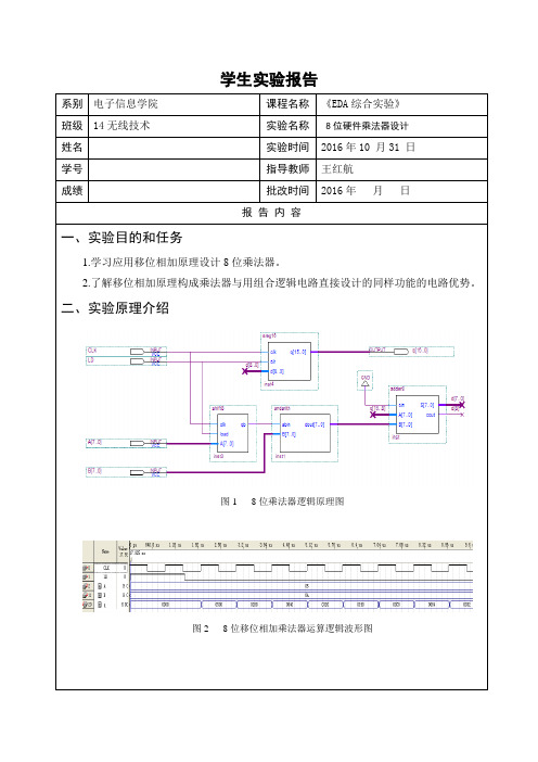
图1 8位乘法器逻辑原理图
图2 8位移位相加乘法器运算逻辑波形图
三、设计代码(或原理图)、仿真波形及分析
input [7:0] A;
output qb;
reg[7:0] reg8;
always@(posedge clk or posedge load)
begin
if(load) reg8<=A;
else reg8[6:0]<=reg8[7:1];//移位相加_8位二进制加法器
end
assign qb=reg8[0];
1.基于时序电路的移位相加乘法器-16位移位寄存器
module sreg(clk,clr,d,q);
input clk,clr;
input [8:0] d;
output[15:0] q;
reg[15:0] reg16;
always@(posedge clk or posedge clr)
- 1、下载文档前请自行甄别文档内容的完整性,平台不提供额外的编辑、内容补充、找答案等附加服务。
- 2、"仅部分预览"的文档,不可在线预览部分如存在完整性等问题,可反馈申请退款(可完整预览的文档不适用该条件!)。
- 3、如文档侵犯您的权益,请联系客服反馈,我们会尽快为您处理(人工客服工作时间:9:00-18:30)。
实验三8位乘法器的设计一、实验目的1)了解8位乘法器的工作原理2)熟悉MAX+plusII软件的基本使用方法3)熟悉EDA实验开发的基本使用方法4)学习VHDL程序中数据对象,数据类型,顺序语句,并行语句的综合使用二、实验内容设计一个由8位加法器构成的以时序逻辑方式设计的8位乘法器。
其乘法原理是:乘法通过逐项位移相加原理来实现,以被乘数的最低位开始,若为1,则乘数左移后与上一次和相加,若为0,左移后以全零相加,直至被乘数的最高位。
三、实验条件开发软件:MAX+plus II 9.23 Baseline硬件设备:装有windows7的pc机四、实验设计1)系统的原理框架图2)VHDL源程序andarith.vhd源代码library ieee;use ieee.std_logic_1164.all;entity andarith isport(abin:in std_logic;din:in std_logic_vector(7 downto 0); dout: out std_logic_vector(7 downto 0)); end entity andarith;architecture art of andarith isbeginprocess(abin, din)isbeginfor i in 0 to 7 loopdout(i)<=din(i)and abin;end loop;end process;end architecture art;arictl.vhd源代码library ieee;use ieee.std_logic_1164.all;use ieee.std_logic_unsigned.all;entity arictl isport(clk:in std_logic; start: in std_logic; clkout:out std_logic; rstall: out std_logic; ariend: out std_logic);end entity arictl;architecture art of arictl issignal cnt4b:std_logic_vector(3 downto 0); beginrstall<=start;process(clk, start)isbeginif start='1' then cnt4b<="0000";elsif clk'event and clk='1'thenif cnt4b<8 thencnt4b<=cnt4b+1;end if;end if;end process;process (clk,cnt4b,start)isbeginif start='0'thenif cnt4b<8 thenclkout<=clk; ariend<='0';else clkout<='0'; ariend<='1';end if;else clkout<=clk; ariend<='0';end if;end process;end architecture art;sreg8b.vhdlibrary ieee;use ieee.std_logic_1164.all;entity sreg8b isport (clk: in std_logic;load: in std_logic;din: std_logic_vector(7 downto 0);qb: out std_logic);end entity sreg8b;architecture art of sreg8b issignal reg8:std_logic_vector(7 downto 0); beginprocess(clk, load)isbeginif clk'event and clk='1'thenif load='1'then reg8<=din;else reg8(6 downto 0)<=reg8(7 downto 1); end if;end if;end process;qb<=reg8(0);end architecture art;reg16b.vhdlibrary ieee;use ieee.std_logic_1164.all;entity reg16b isport(clk: in std_logic;clr: in std_logic;d: in std_logic_vector(8 downto 0);q: out std_logic_vector(15 downto 0));end entity reg16b;architecture art of reg16b issignal r16s: std_logic_vector(15 downto 0);beginprocess(clk,clr)isbeginif clr='1'then r16s<="0000000000000000";elsif clk'event and clk='1'thenr16s(6 downto 0)<=r16s(7 downto 1);r16s (15 downto 7)<=d;end if ;end process;q<= r16s ;end architecture art;Adder8b.vhd源代码library ieee;use ieee.std_logic_1164.all;use ieee.std_logic_unsigned.all;entity adder8b isport( c8:in std_logic;a8:in std_logic_vector(7 downto 0);b8: in std_logic_vector(7 downto 0);s8: out std_logic_vector(7 downto 0);co8: out std_logic);end entity adder8b ;architecture art of adder8b iscomponent adder4b isport(c4: in std_logic;a4: in std_logic_vector(3 downto 0);b4: in std_logic_vector(3 downto 0);s4: out std_logic_vector(3 downto 0);co4: out std_logic);end component adder4b;signal sc:std_logic;beginu1:adder4bport map(c4=>c8,a4=>a8(3 downto 0),b4=>b8(3 downto 0), s4=>s8(3 downto 0),co4=> sc);u2:adder4bport map(c4=>sc, a4=>a8(7 downto 4),b4=>b8(7 downto 4),s4=>s8(7 downto 4),co4=>co8);end architecture art;multi8x8.vhdlibrary ieee;use ieee.std_logic_1164.all;entity multi8x8 isport(clk: in std_logic;start: in std_logic;a: in std_logic_vector(7 downto 0);b: in std_logic_vector(7 downto 0);ariend: out std_logic;dout: out std_logic_vector(15 downto 0));end entity multi8x8;architecture art of multi8x8 iscomponent arictl isport(clk:in std_logic;start: in std_logic;clkout:out std_logic;rstall:out std_logic;ariend:out std_logic);end component arictl;component andarith isport(abin: in std_Logic;din: in std_logic_vector(7 downto 0);dout:out std_logic_vector(7 downto 0));end component andarith;component adder8b isport( c8:in std_logic;a8:in std_logic_vector(7 downto 0);b8: in std_logic_vector(7 downto 0);s8: out std_logic_vector(7 downto 0);co8: out std_logic);end component adder8b;component sreg8b isport (clk: in std_logic;load: in std_logic;din: std_logic_vector(7 downto 0);qb: out std_logic);end component sreg8b;component reg16b isport(clk: in std_logic;clr: in std_logic;d: in std_logic_vector(8 downto 0);q: out std_logic_vector(15 downto 0));end component reg16b;signal s1:std_logic;signal s2:std_logic;signal s3:std_logic;signal s4:std_logic;signal s5:std_logic_vector(7 downto 0);signal s6:std_logic_vector(8 downto 0);signal s7:std_logic_vector(15 downto 0);begindout<=s7;s1<='0';u1:arictl port map(clk=>clk,start=>start,clkout=>s2,rstall=>s3,ariend=>ariend);u2:sreg8b port map(clk=>s2,load=>s3,din=>a,qb=>s4);u3:andarith port map(abin=>s4,din=>b,dout=>s5);u4:adder8b port map(c8=>s1,a8=>s7(15 downto 8),b8=>s5,s8=>s6(7 downto 0),co8=>s6(8));u5:reg16b port map(clk=>s2,clr=>s3,d=>s6,q=>s7);end architecture art;3)管脚图五、实验结果及总结系统时序仿真结果从系统仿真结果可以看出,本系统完全符合设计要求,同时从仿真结果可以看出,从输入到输出有一定的延时,在11ns左右,这正是器件延时特征的反映。