medln83se伺服说明书
亚特兰蒂斯电源自动切断器类型W、WV和WV38X功能规范指南说明书

ReclosersFunctional Specification GuideTypes W, WV and WV38X ReclosersPS280023EN1 of2 • Effective June 2017 • Supersedes May 1997 ©2017 Eaton. All Rights Reserved.Functional specification for Types W, WV and WV38X reclosers1. Equipment Specifications1.1. Automatic Circuit Reclosers with series trip oil interruption, oil insulation2. Standards2.1. The reclosers covered by this specification shall be manufactured and tested in accordance with ANSIC37.60. 3. RatingsW WV WV38X Maximum Design Voltage, kV15.5 27.0 38.0 Nominal Operating Voltage, kV 2.4-14.424.9 34.5 Basic Insulation Level (BIL), kV 110 150 170 60 Hertz Withstand Voltage, kV Dry, One Minute 50 60 70Wet, Ten Seconds45 50 60 Continuous Current Rating, Amps560560 560 Interrupting Rating, Symmetric Amps 10,**********8000800012,*********4. Duty cyclePERCENT OF NUMBER OF MAXIMUM INTERRUPTING UNIT CIRCUIT TYPE RATING OPERATIONS X/R VALUE W 15-20 28 3 45-55 20 790-10010 14WV & WV38X 15-20 28 4 45-55 20 890-10010155. Recloser features5.1. The recloser shall be mechanically and electrically trip free.5.2. All three poles of the recloser shall be operated simultaneously by a solenoid-controlled spring operatingmechanism.Types W, WV and WV38X Reclosers PS280023EN5.3. The recloser shall be completely self-contained. No auxiliary power source shall be required.5.4. The solenoid shall provide energy for closing the main contacts and for storing energy in the openingspring for a tripping operation.5.5. The closing solenoid coil shall be connected internally phase-to-phase on the source side of the recloserthrough a suitable contactor.5.6. Bushings shall be of wet process porcelain, terminals shall be of the universal clamp type and shallaccommodate number 1/0 through 500 MCM conductor.5.7. Bushing creepage distance shall be (11 5/8" for type W, 26½ for type WV & WV38X.5.8. Contact assemblies shall be of the double break type.5.9. A three-stage auxiliary switch shall be provided.5.10. The recloser interrupting time shall be 0.045 seconds maximum.5.11. The recloser shall be shipped filled with oil to the proper level. A dipstick shall be provided for checking oillevel, a low oil level sight gauge shall be provided.5.12. The recloser shall be shipped mounted on a substation type frame, complete with a tank lifting windlass.5.13. The mounting frame shall have a grounding pad which will accommodate two No. 2/0 to 250 MCMconductors.5.14. Manually closing and opening shall be accomplished by means of a manual operating handle locatedunder a sleet hood external to the recloser. This handle shall also provide indication of recloser lockout.5.15. A contact position indicator shall be provided, located under the recloser sleet hood.5.16. One operation to lockout (non-reclosing) shall be accomplished by means of an external handle locatedunder the sleet hood.5.17. An operations counter shall be provided to count recloser operations, located under the sleet hood.5.18. Overcurrent detection shall be provided by a set of three series trip coils, one per phase.5.19. Time delay on tripping shall be provided by a set of three time delay units, one per phase.5.20. The number of fast phase trip operations shall be selectable by means of a Sequence Selector internallylocated in the recloser. Selections shall be 0 - 1 - 2 - 3 - 4 number of fast trip operations.5.21. The number of operations to lockout shall be selectable from 2 to 4 operations by means of an operationsselector internally located in the recloser.6. Approved ManufacturersEaton2 of 2 • June 2017 • Supersedes May 1997©2017 Eaton. All Rights Reserved.。
乐邦伺服控制器说明书

乐邦伺服控制器说明书
1、脉冲控制方法。
在一些小型单机设备上,使用脉冲控制来确定电动机的位置应该是最常用的应用方法。
这种控制方法简单易懂,基本控制思路:脉冲总量决定电机位移,脉冲频率决定电机速度。
2、模拟控制方法。
在需要使用伺服电动机实现速度控制的应用场景中,可以使用仿真量实现电动机的速度控制,仿真量决定了电动机的工作速度。
模拟量有两种选择:电流或电压。
电压方法只需要在控制信号的末端加上一定大小的电压。
实现很简单。
在某些场景中,可以使用电位器控制。
但是,如果选择电压作为控制信号,则在环境复杂的场景中,电压容易受到干扰,导致控制不稳定。
电流模式,需要相应的电流输出模块。
但是电流信号抗干扰能力强,可以在复杂的场景中使用。
3、通信控制方法。
以通信方式实现伺服电动机控制的常用方法有CAN、EtherCAT、Modbus和Profibus。
使用通信方式控制电动机是目前将场景应用于复杂大型系统的首选控制方法。
使用通信方式,系统尺寸、电机轴的量可以轻松切割,没有复杂的控制接线,构建的系统非常灵活。
伺服电动机的速度控制和转矩控制都是由模拟量控制的,位置控制由脉冲控制,具体采用什么控制方式要根据客户的要求,如果对电动机的速度、位置没有要求,只要输出一定的转矩,
就可以使用转矩模式。
麦克塞斯ip-80电流至压力转换器使用手册说明书
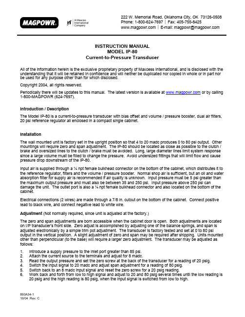
222 W. Memorial Road, Oklahoma City, OK 73126-0508Fax: 405-755-8425Phone:1-800-624-7697E-mail:*******************INSTRUCTION MANUALMODEL IP-80Current-to-Pressure TransducerAll of the information herein is the exclusive proprietary property of Maxcess International, and is disclosed with theunderstanding that it will be retained in confidence and will neither be duplicated nor copied in whole or in part norbe used for any purpose other than for which disclosed.Copyright 2004, all rights reserved.Periodically there will be updates to this manual. The latest version is available at or by calling1-800-MAGPOWR (624-7697).Introduction / DescriptionThe Model IP-80 is a current-to-pressure transducer with bias offset and volume / pressure booster, dual air filters,20 psi reference regulator all enclosed in a compact single cabinet.InstallationThe wall mounted unit is factory set in the upright position so that 4 to 20 madc produces 0 to 80 psi output. Othermountings will require zero and span adjustment. The IP-80 should be located as close as possible to the clutch /brake and oversized lines to the clutch / brake must be avoided. Long, large diameter lines limit system responsesince a large volume must be filled to change the pressure. Avoid undersized fittings that will limit flow and causepressure drop downstream of the IP-80.Input air is supplied through a ¼ npt female bulkhead connector on the bottom of the cabinet, which distributes it tothe reference regulator, filters and the volume / pressure booster. Normal shop air is sufficient, but an oil and waterabsorption filter for supply air is recommended if air quality is unknown. Input pressure must be 5 psi greater thanthe maximum output pressure and must also be between 35 and 250 psi. Input pressure above 250 psi candamage the unit. The outlet port is also a ¼ npt female bulkhead connector and also located on the bottom of thecabinet.Electrical connections (2 wires) are made through a 7/8 in. cutout on the bottom of the cabinet. Connect positivelead to black wire, and connect negative lead to white wire.Adjustment (Not normally required, since unit is adjusted at the factory.)The zero and span adjustments are born accessible when the cabinet door is open. Both adjustments are locatedon I/P transducer’s front side. Zero adjust is accomplished by adjusting one of the balance springs, and span isadjusted electronically by a simple trim pot adjustment. The transducer is factory tested and set at 0 to 80 psioutput in the vertical position. A slight adjustment of zero and span may be required after shipping. Units mountedother than perpendicular (to the base) will require a larger zero adjustment. The transducer may be adjusted asfollows:1. Introduce a supply pressure to the inlet port greater than 85 psi.2. Attach the current source to the terminals and adjust for 8 madc.3. Read the output pressure and set the zero screw at the back of the transducer for a reading of 20 psig.4. Switch the input signal to 20 madc and adjust span adjustment for a reading of 80 psig.5. Switch back to an 8 madc input signal and reset the zero screw for a 20 psig reading.6. Work back and forth from low to high signal and adjust to 20 and 80 psig several times until the low reading is20 psig and the high reading is 80 psig, when the input signal is switched from low to high.850A34-1SpecificationsOutput:Maximum supply pressure: Input:Minimum supply pressure: Flow Capacity:Exhaust Capacity:Shock and Vibration Effect on Output Pressure: Brake Pressure Gage: Filters (2):Maintenancepressure drop in the filters. RepairWiring DiagramDimensions1.16 [28 mm]。
美国诊断公司ADC肌肤血液压力计器配件说明书

ADC®SphygmomanometerZubehörGebrauchsanweisung,Pflege & WartungAMERICAN DIAGNOSTIC CORPORA TIONADC®Sphygmomanometer Ersatzteile(Manometer, Manschette, Blase, Birne und Ventil)Verwendungszweck:ADC® Blutdruckmanometer sind für die Verwendung mitADC® und kompatiblen nichtinvasiven Blutdruckmanschet-ten ausgelegt. Sie sind für den Einsatz mit kompatiblen In-flationssystemen und in Verbindung mit einem Stethoskopzur manuellen Blutdruckmessung bestimmt.SymboldefinitionenFolgende Symbole sind mit Ihrem ADC® Sphygmomanometer verbunden:Allgemeine Warnungen:WARNUNG:Wenn dieses Gerät modifiziert wird, müssen entsprechende Inspektionen und Prüfungen durchgeführt werden, um die sichere Verwendung sicherzustellen.WARNUNG:Dieses Produkt kann eine Chemikalie enthalten, die dem Staat Kalifornien bekannt ist, um Krebs, Geburtsfehler oder andere Reproduktionsschäden zu verursachen.WARNUNG:Lassen Sie keine Blutdruckmanschette mehr als 10 Minuten bei Patienten auf, wenn sie über 10 mmHg aufgeblasen werden. Dies kann dazu führen, dass Patienten Bedräng-nis, Störung der Durchblutung, und dazu beitragen, die Verletzung der peripheren Nerven.WARNUNG:Wenden Sie keine Manschette an empfindliche oder beschädigte Haut an.Überprüfen Sie die Manschette häufig auf Reizungen.WARNUNG:Sicherheit und Wirksamkeit mit Neugeborenenmanschettengrößen 1 bis 5 ist nicht festgelegt.WARNUNG:Das Taschenmodometer ist für den Einsatz mit TWO-Rohrsystemen ausgelegt, bei denen ein Rohr mit dem Manometer verbun-den ist und das andere mit der Inflationsquelle (Lampe und Ventil) verbunden ist.Anschließen des Manometers an das Inflationssystem:Pocket Style Modelle: 800, 802, 808N, 809NDer Widerhaken an der Unterseite des Manometers wird Reibung passen auf dieSchläuche der meisten handelsüblichen zwei Schlauchmanschetten und Blasen-systeme.WARNUNG:Verwenden Sie nur die Manschette, wenn die auf der Manschette angegebenen Bereichsmarkierungen zeigen, dass die richtige Manschettengröße ausgewählt ist, da sonst fehlerhafte Messungen auftreten können.WARNUNG:Raum zwischen Patient und Manschette zulassen Zwei Finger sollten in diesen Raum passen, wenn die Manschette richtig positioniert ist.WARNUNG:Wenden Sie keine Manschette an die für die IV-Infusion verwendeten Glied-maßen an.WARNUNG:Der Patient sollte während der Messung still bleiben, um fehlerhafte Messwerte zu vermeiden.WARNUNG:Wenn Luer-Lock-Steckverbinder bei der Konstruktion von Schläuchen ver-wendet werden, besteht die Möglichkeit, dass sie versehentlich mit intravaskulären Fluidsys-temen verbunden sind, so dass Luft in ein Blutgefäß gepumpt werden kann. Sofort Arzt konsultieren, falls dies der Fall ist.ACHTUNG:Um die größtmögliche Genauigkeit von Ihrem Blutdruckmessgerät zu erhalten,empfiehlt es sich, das Gerät in einem Temperaturbereich von 50 ° F (10 ° C) bis 104 ° F (40° C) mit einem relativen Feuchtigkeitsbereich von 15% -85% (nicht kondensierend).ACHTUNG:Manometer Druckbereich ist 0 mmHg bis 300 mmHg.ACHTUNG:Extreme Höhen können Blutdruckmessungen beeinflussen. Ihr Gerät wurde für normale Umgebungsbedingungen konzipiert.ACHTUNG:ieses Produkt behält die Sicherheits- und Leistungsmerkmale bei Temperaturen von 32 ° F bis 104 ° F (0 ° C bis 40 ° C) bei einer relativen Luftfeuchtigkeit von 15% bis 85% bei.ACHTUNG:Bündel nicht bügeln.ACHTUNG:Die Manschette nicht erhitzen oder dämpfen.Palm Style Modell: 804NMontieren Sie den mitgelieferten Luer-Steckverbinder auf das freie Ende des Man-schettenrohres, indem Sie das Stacheldrähstück in den Schlauch einsetzen. DerSteckverbinder wird auf die Schläuche der meisten handelsüblichen ONE-Rohrmanschetten- und Blasensysteme aufgesteckt. Setzen Sie den Luer-Slip-Stecker in den Port an der Oberseite des Palm-Manometers ein und drehen Sie ihnleicht ein.WARNUNG:Das Palmen-Manometer ist für den Einsatz mit ONE-Rohrsystemen ausgelegt.WARNUNG:Um eine Beschädigung des Gerätes zu vermeiden, darf der Steckernicht in den Anschluss geschoben werden.Uhr Modell: 805Der Widerhaken an der Unterseite des Manometers wird auf die meistenhandelsüblichen Spiralschläuche reibend anliegen.WARNUNG:Das Uhren-Manometer ist für den Einsatz mit TWO-Rohrsystemen konzipiert, bei denen ein Rohr mit dem an dasManometer angebrachten Spiralrohr verbunden ist und das anderemit der Aufblasquelle (Lampe und Ventil)WARNUNG:Für alle Blutdrucksysteme, die an der Wand montiertwerden können, sicherstellen, dass das Gerät vor dem Gebrauchsicher befestigt ist, um eine Beschädigung des Gerätes und einemögliche Verletzung des Patienten zu vermeiden.Maintenance:Das Manometer kann mit einem weichen Tuch gereinigt werden, darf aber unter keinen Umstän-den zerlegt werden. Die Genauigkeit des Messgerätes kann visuell überprüft werden. Achten Sie darauf, dass die Nadel in dem gedruckten Oval liegt, wenn das Gerät vollständig entleert ist.Sollte die Indikatornadel des Manometers außerhalb dieser Kalibriermarke liegen, so muss das Manometer im Vergleich zu einem Referenzgerät, das nach na-tionalen oder internationalen Messstandards zertifiziert wurde, in-nerhalb von ± 3 mmHg neu kalibriert werden. Keine Manometer,deren Indikatornadel außerhalb dieser Markierung ruht, sind für den Gebrauch akzeptabel (Abbildung 1). Der Hersteller empfiehlt alle 2 Jahre eine Kalibrierprüfung.Normen:ANSI/AAMI/ISO 81060-1:2007 • EN / ISO 81060 - 1:2012HINWEIS: Speichern Sie mit Ventil in voller Auspuffposition.(Abbildung 1)Blase Modell: Serie 815Verwendungszweck:ADCUFF ™ Blasen sind nicht invasive Inflationstaschen, die für die Verwendung mit ADC® und kompatiblen Blutdruckmanschetten entwickelt wurden. Sie sind für den Einsatz mit manuellen und automatisierten nichtinvasiven Blutdruckmessgeräten bestimmt.Zusammenbau der Cabrio BlaseConveritble Blase Anschlüsse (1 oder 2 Röhrchen)WARNUNG:Verbindungen sind nicht so konzipiert, dass sie regelmäßig hin- und herbe-wegbar sind.Einfügen von Blase in die ManschetteManschettenmodelle:Serie 845Verwendungszweck:ADC® Blutdruckmanschetten sind nichtinvasive Blutdruckmanschetten, die für die Verwendung mit manuellen und automatisierten nichtinvasiven Blut-druckmessgeräten bestimmt sind.Kontraindikationen:Aneroid-Blutdruckmessgeräte sind für die Verwendung von Neugeborenen kontraindiziert. Nicht mit neonatalen Manschetten oder Neugeborenen ver-wenden. Überprüfen Sie die Größendia-gramm für das richtige Alter und den Gliedmaßenbereich (rechts).Manschette GrößeGliedmaßenZoll CMSäugling 7 3.5 bis 5.5 9 bis 14 Kind 9 5.1 bis 7.6 13 bis 19.5 Kleine Erwachsene10 7.4 bis 10.6 19 bis 27 Erwachsene11 9 bis 15.7 23 bis 40 Großer Erwachsener 12 13.3 bis 19.6 34 bis 50 Schenkel 13 15.7 bis 25.9 40 bis 66 Bariatric12 17.32 bis 25.9 44 bis 66GrößentabelleGröße GuideTM Markierungssystem:ADC®'s Size Guide ™ Markierungssystem sorgt für die Verwendung der richtigen Manschet-tengröße und der richtigen Manschettenausrichtung. Printed Index und Range Markierungen und anwendbare Gliedmaßen (in cm) ermöglichen eine einfache Erkennung der richtigen Man-schettengröße. Eine auf beiden Seiten bedruckte Arterienmarkierung zeigt den Blasen-Mit-telpunkt für die korrekte Manschettenpositionierung an. Ein bequemes Nylon-Hang-Tag erlaubt den flexiblen Einsatz mit Pocket-Aneroiden oder Quecksilber-Manometern. Haken- und Loop-Klebeflächen sorgen für eine stabile, stufenlose Passform und sind so konzipiert, dass sie min-destens 30.000 Öffnungs- / Schließzyklen aushalten können.Anwendung Cuff:Legen Sie die Manschette über den nackten Oberarmmit der Arterienmarkierung, die direkt über der Arteriabrachialis positioniert ist. Die untere Kante der Man-schette sollte ungefähr (1 ") ein Zoll (2-3cm) über derantecubital Falte positioniert werden.Wickeln Sie das Ende der Manschette NICHT mit der Blase um Arm eng und glatt und greifen Klebestreifen.Um eine korrekte Passform zu überprüfen, überprüfenSie, ob die INDEX-Zeile zwischen die beiden RANGE-Linien fällt (Abbildung 5).Gauge HangHaken & Loop Linker ArmInstandhaltung:Reinigen und desinfizieren nach BedarfReinigung• Verwenden Sie eine oder mehrere der folgenden Methoden und lassen Sie die Luft trocknen:• Mit mildem Reinigungsmittel und Wasserlösung (1: 9-Lösung) abwischen. Spülen.• Wenden Sie sich mit Enzol nach den Anweisungen des Herstellers ab. Spülen.• Mit 5% Bleich- und Wasserlösung abwischen. Spülen.• Mit 70% Isopropylalkohol abwischen.• Mit mildem Reinigungsmittel in warmem Wasser abwaschen, normaler Waschzyklus.Blase zuerst entfernen. Manschette ist mit 5 Waschzyklen kompatibel.Low-Level-DesinfektionBereiten Sie Enzol enzymatische Reinigungsmittel gemäß den Anweisungen des Herstellers vor. Sprühen Sie die Waschmittellösung auf die Manschette und verwenden Sie eine sterile Bürste, um die Waschmittellösung über die gesamte Manschettenoberfläche für fünf Minuten zu rühren.Spülen Sie kontinuierlich mit destilliertem Wasser für fünf Minuten. Zur Desinfektion, folgen Sie zuerst den Reinigungsschritten oben, dann Spray Manschette mit 10% Bleichlösung bis gesättigt, rühren mit einer sterilen Bürste über die gesamte Manschette Oberfläche für fünf Minuten. Spülen Sie kontinuierlich mit destilliertem Wasser für fünf Minuten. Wischen Sie überschüssiges Wasser mit sterilem Tuch ab und lassen Sie die Manschette an der Luft trocknen.Glühlampe und Ventilbaugruppe - Modell 872NVerwendungszweckADC® Blutdruckbirne und Ventile ermöglichen eine kontrol-lierte Inflation und Entleerung der Blutdruckmanschette. Siesind für den Einsatz mit manuellen nichtinvasiven Blut-druckmessgeräten bestimmt.Zu Bedienen:Schließen Sie das Ventil, indem Sie die Rändelschraube im Uhrzeigersinn drehen. Zu öffnen, gegen den Uhrzeigersinn drehen. Die Deflation sollte bei einer konsistenten Rate von 2-3mmHg / Sekunde während der Messung für beste Ergebnisse (gemäß den Empfehlungen des AHA) aufrechterhalten werden.Instandhaltung:Ihre Glühbirne und Ventil-Baugruppe ist mit einem Endventil ausgestattet, das die Aufnahme von Luft in Ihr Blutdruckgerät ermöglicht. Es wird empfohlen, dass das Endventil auf Schutt überprüft und regelmäßig gereinigt wird, um sicherzustellen, dass Staub und andere Ablagerun-gen den Luftstrom nicht reduzieren. HINWEIS: Einige Endventile sind mit einem Filterschirm ausgestattet, um das Eindringen von Staub aus der Umgebung zu verhindern.Manometer QualitätskontrolleEine Seriennummer und eine Losnummer werdenjedem Aneroid während der Fertigung automatischzugewiesen, so dass jeder Artikel "kontrolliert" ist.Diese Seriennummer kann sich auf der Frontplattejedes Aneroids befinden (Abbildung 6).Die Losnummer befindet sich auf dem Außenetikettaller Zubehörverpackungen (Bild 7).VerfügungWenn Ihr Blutdruckmessgerät oder irgendwelche seiner Teile sein Ende des Lebens erreicht haben, bitte achten Sie darauf, es in Übereinstimmung mit allen regionalen und nationalen Umweltvorschriften zu entsorgen. Verschmutzte Geräte müssen gemäß den örtlichen Verordnun-gen und Vorschriften entsorgt werden.(Abbildung 6)OrdnungsnummerChargennummerGarantieDer ADC®-Garantieservice der American Diagnostic Corporation erstreckt sich nur auf den ur-sprünglichen Einzelhandelskäufer und beginnt ab dem Datum der Lieferung. ADC garantiert seine Produkte gegen Material- und Verarbeitungsfehler bei normaler Benutzung und Wartung wie folgt:• Ihr Manometer ist für 10 Jahre, 20 Jahre oder Leben abhängig vom Modell gerechtfer-tigt. Beziehen Sie sich auf Etikett oder Endplatte für spezifische Garantiebezeichnung.Das Manometer ist berechtigt, bis zu +/- 3mmHg (oder dem vorherrschenden Standard)über seine volle Reichweite im Vergleich zu einem Referenzstandard für das Leben genau zu bleiben.• AdcuffTM Inflation Systemkomponenten (Manschette, Blase, Schlauch, Glühlampe, Ventile, Steckverbinder) sind für drei Jahre gerechtfertigt. Spezielle Manschetten undBlasen sind für 2 Jahre garantiert.Was ist abgedeckt:Ersatz von Teilen und Arbeit.Was ist nicht abgedeckt: Transportkosten von und von ADC®. Schadensersatz wegen Missbrauch, Missbrauch, Unfall oder Fahrlässigkeit. Neben-, Sonder- oder Folgeschäden. Einige Staaten erlauben nicht den Ausschluss oder die Beschränkung von zufälligen, beson-deren oder Folgeschäden, so dass diese Beschränkung nicht für Sie gelten kann.Um den Garantieservice zu erhalten: Sende Artikel per Post an ADC®, Attn: Repair Dept., 55 Commerce Dr., Hauppauge, NY 11788. Bitte geben Sie Ihren Namen und Ihre Adresse, Telefonnummer, Kaufbeleg und kurz an Notiz erklären das Problem.Implizierte Gewährleistung:Jede stillschweigende Gewährleistung ist in der Dauer auf die Bedingungen dieser Gewährleistung und in keinem Fall über den ursprünglichen Verkauf-spreis hinaus begrenzt (außer wenn gesetzlich verboten). Diese Garantie gibt Ihnen bestimmte gesetzliche Rechte und Sie können andere Rechte haben, die von Staat zu Staat variieren.11ADC 55 Commerce Drive Hauppauge, NY 11788U.S.A.ADC (UK) Ltd.Unit 6, PO14 1THUnited KingdomInspektion & Verpackung in der U.S.A.tel: 631-273-9600Gebührenfrei: 1-800-232-2670fax: *****************IB p/n 9355N-00 rev 4Gedruckt in der U.S.A.Um Ihr Produkt zu registrieren, besuchen Sie uns unter/register。
得玛莎三代水光仪器电子注射器说明书使用手册

User’s Manual(K2017)1st Edition (4 Apr 17)本机器为医疗器械。
为了保证产品的安全使用,请您在使用之前仔细阅读说明书。
得玛莎三代的维修制度是根据优美医院有限公司的维修制度进行。
( www.umedis.kr )1. 产品介绍1.1 产品介绍DermaShine® PRO(得玛莎三代)是创新数字注射器系统(带吸螺杆多针)利用Dermashine 吸气。
多螺杆针由 9 根针组成,更容易嵌入硬注射部位。
得玛莎三代吸气通过提拉硬注射部位,使之得以方便注入。
过程同时进行,使注射出奇地容易和快速。
DermaShine® PRO的优点DermaShine® PRO注射器会在您所需的深度注入等量的药品。
(0-2 毫米)的注入点均匀分布。
①在1~2mm注射部位有效率地注入药品的DDS (Drug Delivery System)医疗器械。
②经过2年多的开发过程,生产出来了更安全更细节的高品质的水光机。
③9针使得处理的效率提高。
花费更少的时间 & 精力。
④缩短恢复时间 & 减轻疼痛,使病人的满意度最大化。
⑤治疗时间不超过7分钟。
⑥通过8ms素的的精细注射模式,提高操作者的便利性。
(取得专利)1.2 使用时注意事项1.使用前请仔细阅读说明书后使用2.药品注射器与灭菌注射器相连时,如果连接太紧,在注射过程中可能发生灭菌注射器与药品注射器分离或药品液体渗漏的情况3.使用抽吸器(Aspirator)时,因药物损失和 breeding 致使药物通过吸管进入注射器内,此情况可能导致本品出现故障,请在使用过程中或使用后随时检查液压阻尼器。
4.如将注射器向上方注射,其损失药品会流入至装置中,可能导致本品出现故障5.拔出电源线时,请握住电源插头将其拔出请勿直接拽拉电源线6.一次注射结束提示音-在 Auto-sensing(自动感应)/Auto-dose(自动剂量)/dose(剂量)等模式下结束药物注射时,注射器自身将会发出声响并停止注射。
海为伺服系统使用说明书

H厦门海为科技有限公司目录前言 (3)1、阅读说明 (3)2、产品检查 (3)3、关于手册 (3)4、图标说明 (3)第一章安全须知 (4)1、使用时之注意事项 (4)2、使用环境之注意事项 (6)第二章硬体说明及安装 (7)1、使用环境 (7)2、型号说明 (10)3、产品规格 (11)4、电机旋转方向定义 (12)5、基本配线图 (12)6、外形尺寸 (15)7、不同模式下接线图说明 (17)8、接口 (20)9、输入/输出接口类型 (23)第三章操作面板说明 (30)1、操作面板说明 (30)2、功能一览 (32)3、控制状态显示模式 (33)4、报警模式 (34)5、参数编辑模式 (35)6、定位数据编辑模式 (36)第四章运行 (37)1、信号的说明(输入信号的优先顺序) (37)2、运行步骤选择 (38)3、运行确认 (39)4、运行 (40)第五章功能参数说明一览表 (53)1、参数的分类 (53)2、功能参数一览表 (53)第六章功能参数详细说明 (60)1、基本设定参数(P1.01~50) (60)2、控制增益、滤波器设定参数(P1.51~99) (72)3、自动运行设定参数(P2.01~50) (79)4、扩展功能设定参数(P2.51~99) (91)5、输入端子功能设定参数(P3.01~50) (98)6、输出端子功能设定参数(P3.51~99) (110)第七章通讯 (125)1、设定伺服驱动器 (125)2、通信规格 (125)3、传输协议 (126)第八章故障指示及对策 (132)1、检查 (132)2、状态显示 (132)3、报警的处理方法 (133)第九章电机 (139)1、伺服电机产品特点 (139)2、伺服电机型号说明 (139)3、伺服电机参数表 (140)4、贮运 (148)5、接线 (148)第十章选件与辅助设备 (149)1、关于选件 (149)2、驱动器制动标准配置 (149)前言非常感谢您选用Haiwell 伺服驱动器!本手册包括Haiwell 伺服驱动器使用时的操作说明和保养注意事项。
Proservo NMS80、NMS81、NMS83 电子设备安全使用说明说明书

Products Solutions ServicesSafety Instructions Proservo NMS80, NMS81, NMS83CA:I / 1 / BCD T6...T1 AIS / I II III / 1 / ABCDEFG; Entity Ex db [ia Ga] IIC / T6...T1 Ga/Gb; EntityANI / I II III / 2 / ABCDEFG; NIFWUS:I / 1 / BCD / T6...T1 AIS I II III / 1 / ABCDEFG; Entity 1 / 0/1 / AEx db [ia Ga] IIC T6...T1 Ga/Gb; Entity ANI / I II III / 2 / ABCDEFG; NIFWDocument: XA01496G-B Safety instructions for electrical apparatuses used in explosion-hazardous areas → 3XA01496G-B/00/EN/03.20714984662020-10-31Proservo NMS80, NMS81, NMS83XA01496G-BProservoNMS80, NMS81, NMS83Table of contentsAssociated documentation (4)Manufacturer address (4)Extended order code (4)Safety instructions: General (7)Safety instructions: Special conditions (8)Safety instructions: Installation (9)Explosionproof / Flameproof (12)Endress+Hauser3XA01496G-B Proservo NMS80, NMS81, NMS834Endress+HauserAssociated documentationThis document is an integral part of the following Operating Instructions:•BA01456G (NMS80)•BA01459G (NMS81)•BA01462G (NMS83)Manufacturer addressEndress+Hauser Yamanashi Co., Ltd.406-0846862-1 Mitsukunugi, Sakaigawa-cho, Fuefuki-shi, Yamanashi Extended order codeThe extended order code is indicated on the nameplate, which is affixed to the device in such a way that it is clearly visible. Additional information about the nameplate is provided in the associated Operating Instructions.Structure of the extended order code NMS8x –*************+A*B*C*D*E*F*G*..(Device type)(Basic specifications)(Optional specifications)* =Placeholder At this position, an option (number or letter) selected from the specification is displayed instead of the placeholders.Basic specifications The features that are absolutely essential for the device (mandatory features) are specified in the basic specifications. The number of positions depends on the number of features available.The selected option of a feature can consist of several positions.Optional specifications The optional specifications describe additional features for the device (optional features).The number of positions depends on the number of features available. The features have a 2-digit structure to aid identification (e.g. JA). The first digit (ID) stands for the feature group and consists of a number or a letter (e.g. J = Test, Certificate). The second digit constitutes the value that stands for the feature within the group (e.g. A = 3.1 material (wetted parts), inspection certificate).More detailed information about the device is provided in the following tables. These tables describe the individual positions and IDs in the extended order code which are relevant to hazardous locations.Extended order code: Proservo The following specifications reproduce an extract from the product structure and are used to assign:•This documentation to the device (using the extended order code on the nameplate).•The device options cited in the document.Proservo NMS80, NMS81, NMS83XA01496G-BDevice typeNMS80, NMS81, NMS83Basic specificationsEndress+Hauser5XA01496G-B Proservo NMS80, NMS81, NMS836Endress+HauserProservo NMS80, NMS81, NMS83XA01496G-B Endress+Hauser 7Optional specifications Safety instructions: General•Staff must meet the following conditions for mounting, electrical installation, commissioning and maintenance of the device:•Be suitably qualified for their role and the tasks they perform •Be trained in explosion protection •Be familiar with national regulations •Install the device according to the manufacturer's instructions and national regulations.•Do not operate the device outside the specified electrical, thermal and mechanical parameters.•Only use the device in media to which the wetted materials have sufficient durability.•Avoid electrostatic charging:•Of plastic surfaces (e.g. housing, sensor element, special varnishing, attached additional plates, ..)•Of isolated capacities (e.g. isolated metallic plates)•Refer to the temperature tables for the relationship between the permitted ambient temperature for the sensor and/or transmitter, depending on the range of application and the temperature class.•Modifications to the device can affect the explosion protection and must be carried out by staff authorized to perform such work by Endress+Hauser.XA01496G-B Proservo NMS80, NMS81, NMS838Endress+HauserSafety instructions:Special conditionsPermitted ambient temperature range at the electronics housing:–40 °C (–40 °F) ≤ T a ≤ +50 (122), +55 (131), or +60 °C (140 °F)Observe the information in the temperature table on page xxxx •Use supply wires suitable for 20 K above the ambient temperature.•In the event of additional or alternative special varnishing on the housing or other metal parts:•Observe the danger of electrostatic charging and discharge.•Do not rub surfaces with a dry cloth.Proservo NMS80, NMS81, NMS83XA01496G-B Endress+Hauser 9Special conditions of use US/CA •Flamepath joints are not for repair. Contact the manufacturer.•Use heat resisting cables rated ≥ 85 °C (185 °F) for T a > 50 °C (122 °F)50 °C.•Precautions shall be taken to minimize the risk from electrostatic discharge of non-metallic labels and isolated metal tags applied to the enclosure.•To maintain the ingress protection ratings (IP66/68), teflon tape or pipe dope is required for blanking plugs.•Explosionproof certified seals are required within 450 mm (17.72 in) on all used housing entries.Safety instructions:InstallationA Division1, Zone 1, or Division21Tank; Division1, Zone 0, or Zone 12Connection and electronics compartment AEx d/Ex d 3Power supply 4Potential equalization line 5Potential equalization •Install the device to exclude any mechanical damage or friction during the application.Pay particular attention to flow conditions and tank fittings.•Continuous service temperature of the connecting cable: –40 to ≥ +xx °C (-40 to + xx °F); in accordance with the range of service temperature taking into account additional influences of the process conditions (Ta,min), (Ta,max +30 K). ( → 9, "Ambient temperature").•The installation of the tank gauge NMS80/81/83 is to be made in such a way that no waving or rolling motion of the displacer can occur in operation causing a contact of the displacer with the tank wall. In case of the drum housing made of aluminum (NMS80), any impact or friction to the equipment has to be avoided in order to prevent an ignition hazard between the drum housing and internal parts.Ambient temperatureXA01496G-B Proservo NMS80, NMS81, NMS83Table1: Basic specification, Position 11, 12 (Housing) = ABTable2:Basic specification, Position 11, 12 (Housing) = AC, AD Configuration of electronics:Table3: Basic specification, Position 11, 12 (Housing) = BC, BD Configuration of electronics:10Endress+HauserProservo NMS80, NMS81, NMS83XA01496G-B Endress+Hauser 11Measure low or high temperature liquid •The process temperature shall not bring the enclosure of the electronics compartment beyond the specified ambient temperature range limits.•When installing high or low temperature storage tank, heat or cold from the liquid, the vapor or tank wall should not be conducted to the NMS8x directly.•Cover the tank with a thermal isolation material and/or install an ambient temperature adjustment pipe between NMS8x and nozzle of the tank.1Ambient temperature adjust pipe (optional)2Terminal isolation material 3Measuring wire 4Displacer 5Tank wall 6High or low temperature liquid The temperature of the flange and the internal temperature of the drum compartment:–40 °C (–40 °F) ≤ T a ≤ +50 (122), +55 (131), or +60 °C (140 °F) (see the table above.)Applicable maximum installation height Although IEC60079 series does not require contents of this section, the following is recommended to increase the safety when using this equipment. In the unlikely case that the displacer wire breaks and the displacer hits the tank bottom there is the possibility of an ignition if the potential energy stored in the displacer is greater than the minimum ignition energy. In order to avoid any ignition hazard the applicable maximum tank height (Hmax) which is depending on displacer weight (Wd)shall be as follows:XA01496G-B Proservo NMS80, NMS81, NMS8312Endress+HauserIn case of a tank gauge installation above the maximum height (Hmax), when the tank is empty and explosive gas/vapor is present, the displacer must be lowered to the tank bottom to avoid any ignition hazard between the displacer and the tank bottom.Separation of Zone 0 and Zone1The partition wall between the drum compartment (Zone 0) and electronic compartment (Zone 1)meets requirement 4.2.5.3 i) of IEC 60079-26. Maximum working pressure of the drum compartment is below.Explosionproof / FlameproofClass I, Div. 1, Groups B, C, D Class I, Zone 1, AEx d [ia] IIC/Ex d [ia] IIC •Install per National Electrical Code (NFPA70) or Canadian Electrical Code, Part I (C22.1),as applicable.•For the maximum supply voltage: See "Connection data" section.•Control room equipment may not use or generate over 250 V rms .•Seal unused entries with approved plugs that correspond to the type of protection. The plastic transport sealing plug does not meet this requirement and must therefore be replaced during installation.•Antenna is intrinsically safe, AEx ia/Ex ia, and suitable for installation in Class I, Division 1 or Class I, Zone 0/1.•Before operation:•Screw in the cover all the way.•Tighten the securing clamp on the cover.•WARNINGS: Substitution of components may impair intrinsic safety.•Do not open when explosive atmosphere is present.Depending on approval be used, following issues to be considered:*71498466*71498466。
迈世通设置说明
迈世通设置说明
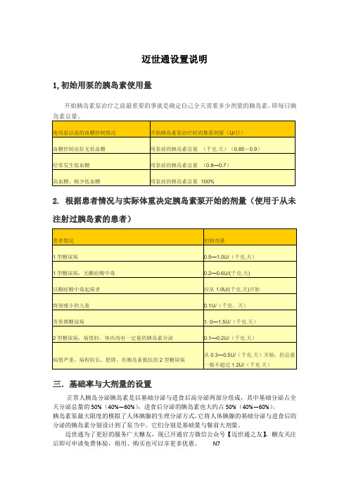
三.基础率与大剂量的设置
正常人胰岛分泌胰岛素是以基础分泌与进食后高分泌两部分组成,其中基础分泌占全天分泌总量的50%(40%—60%),进食后分泌的胰岛素也大约占50%(40%—60%)。
胰岛素泵最大限度的模拟了人体胰腺的生理分泌方式,它将人体胰腺的基础分泌与进食后的分泌的胰岛素分别设计到了泵当中。
它们分别是基础量与餐前大剂量。
迈世通为了更好的服务广大糖友,现已开通官方微信公众号【迈世通之友】,糖友关注后即可申请免费体验,租用、购买也可以享更多优惠。
N7。
- 1、下载文档前请自行甄别文档内容的完整性,平台不提供额外的编辑、内容补充、找答案等附加服务。
- 2、"仅部分预览"的文档,不可在线预览部分如存在完整性等问题,可反馈申请退款(可完整预览的文档不适用该条件!)。
- 3、如文档侵犯您的权益,请联系客服反馈,我们会尽快为您处理(人工客服工作时间:9:00-18:30)。
medln83se伺服说明书
(原创版)
目录
1.介绍 medln83se 伺服说明书
2.概述 medln83se 伺服系统的特点和功能
3.详细说明 medln83se 伺服系统的操作步骤
4.提供 medln83se 伺服系统的维护和故障排除建议
5.总结 medln83se 伺服说明书的主要内容
正文
medln83se 伺服说明书是一本详细讲解如何使用和维护 medln83se 伺服系统的技术手册。
medln83se 伺服系统是一种高性能的伺服系统,具有精确控制、高速响应和稳定运行等特点,广泛应用于各种工业自动化设备中。
概述 medln83se 伺服系统的特点和功能,它采用闭环控制系统,能够精确控制电机的转速、位置和扭矩。
它还具有自适应控制功能,能够根据负载变化自动调整控制参数,以保证系统运行的稳定性。
此外,它还具有丰富的通信接口和扩展能力,能够方便地与其他设备组成工业自动化系统。
详细说明 medln83se 伺服系统的操作步骤,它包括系统配置、参数设置、控制模式选择和运行调试等步骤。
在使用前,需要根据实际应用需求进行系统配置,包括选择电机型号、设定控制参数等。
在参数设置中,需要根据负载特性设置电机的额定电流、额定转速等参数。
在选择控制模式时,需要根据实际控制需求选择速度控制、位置控制或扭矩控制等模式。
在运行调试中,需要对系统进行运行测试,以确保系统的稳定性和可靠性。
提供 medln83se 伺服系统的维护和故障排除建议。
为了保证系统的
正常运行,需要定期进行清洁、润滑和检查等维护工作。
如果出现故障,需要根据故障现象进行排除,可能的原因包括电源故障、通信故障和电机故障等。