刀具与夹具英文文献
加工工艺及夹具毕业设计论文 毕业设计
1
2
3
4
5
6
7
8
9
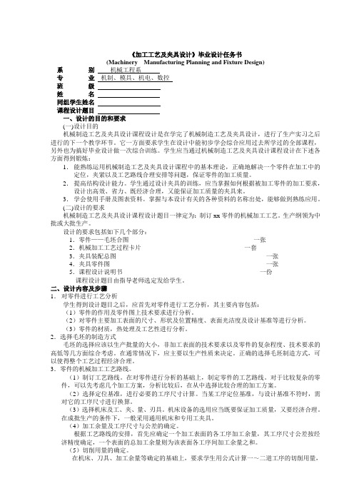
图 2-1 犁刀变速齿轮箱传动示意图 1-左臂壳体 2-犁刀变速齿轮箱体 3-操纵杆 4-啮合套 5-犁刀传动齿轮
6-轴承 7-右臂壳体 8 犁刀传动轴 9-链轮
(二)零件的工艺分析
由附图 1 得知,其材料为 HT200。该材料具有较高的强度、耐磨性、耐热性及减振性,适用于
承受较大应力、要求耐磨的零件。
1.6
G
80
66±0.20
168±2
Φ8N8(--00..000235 )深12 0.1 B
D
4-M12-6H22 0.5 R B D 孔深28
40
Q
3.2
R12 4-Φ22 锪平
18
其余
50° 50° 47
Φ102
A-A
B
Φ80H7(+00.030)
3.2
0.04 A-B
B向
0 -0.1
38
R5
6
2. 提高结构设计能力。学生通过设计夹具的训练,应当掌握如何根据被加工零件的加工要求, 设计出高效、省力、既经济合理,又能保证加工质量的夹具来。
3. 学会使用手册及图表资料。掌握与本设计有关的各种资料的名称出处,能够做到熟练应用。 (二)设计的要求 机械制造工艺及夹具设计课程设计题目一律定为:制订 xx 零件的机械加工工艺。生产纲领为中 批或大批生产。
班
级
学
生
指 导 教师
教研室主任
200 年 月
一、零件的分析 (一)零件的作用 犁刀变速齿轮箱体是旋耕机的一个主要零件。旋耕机通过该零件的安装平面(即附图 1 零件图 上的 N 面)与手扶拖拉机变速箱的后部相连,用两圆柱销定位,四个螺栓固定,实现旋耕机的正确 联接。N 面上的 4-Φ13mm 孔即为螺栓联接孔,2-Φ10F9 孔为定位销孔。 如图 2-1 所示,犁刀变速齿轮箱体 2 内有一个空套在犁刀传动轴上的犁刀传动齿轮 5,它与变 速箱的一倒档齿轮常啮合(图中未画出)。犁刀传动轴 8 的左端花键上套有啮合套 4,通过拔叉可以 轴向移动。啮合套 4 和犁刀传动齿轮 5 相对的一面都有牙嵌,牙嵌结合时,动力传给犁刀传动轴 8。 其操作过程通过安装在 SΦ30H9 孔中的操纵杆拔叉而得以实现。
机械加工刀具中英文对照外文翻译文献

中英文对照外文翻译英文原文Selection of optimum tool geometry and cutting conditionsusing a surface roughness prediction model for end milling Abstract Influence of tool geometry on the quality of surface produced is well known and hence any attempt to assess the performance of end milling should include the tool geometry. In the present work, experimental studies have been conducted to see the effect of tool geometry (radial rake angle and nose radius) and cutting conditions (cutting speed and feed rate) on the machining performance during end milling of medium carbon steel. The first and second order mathematical models, in terms of machining parameters, were developed for surface roughness prediction using response surface methodology (RSM) on the basis of experimental results. The model selected for optimization has been validated with the Chi square test. The significance of these parameters on surface roughness has been established with analysis of variance. An attempt has also been made to optimize the surface roughness prediction model using genetic algorithms (GA). The GA program gives minimum values of surface roughness and their respective optimal conditions.1 IntroductionEnd milling is one of the most commonly used metal removal operations in industry because of its ability to remove material faster giving reasonably good surface quality. It is used in a variety of manufacturing industries including aerospace and automotive sectors, where quality is an important factor in the production of slots, pockets, precision moulds and dies. Greater attention is given to dimensional accuracy and surface roughness of products by the industry these days. Moreover, surface finish influences mechanical properties such as fatigue behaviour, wear, corrosion, lubrication and electrical conductivity. Thus, measuring and characterizing surface finish can be considered for predicting machining performance.Surface finish resulting from turning operations has traditionally received considerable research attention, where as that of machining processes using multipoint cutters, requires attention by researchers. As these processes involve large number of parameters, it would bedifficult to correlate surface finish with other parameters just by conducting experiments. Modelling helps to understand this kind of process better. Though some amount of work has been carried out to develop surface finish prediction models in the past, the effect of tool geometry has received little attention. However, the radial rake angle has a major affect on the power consumption apart from tangential and radial forces. It also influences chip curling and modifies chip flow direction. In addition to this, researchers [1] have also observed that the nose radius plays a significant role in affecting the surface finish. Therefore the development of a good model should involve the radial rake angle and nose radius along with other relevant factors.Establishment of efficient machining parameters has been a problem that has confronted manufacturing industries for nearly a century, and is still the subject of many studies. Obtaining optimum machining parameters is of great concern in manufacturing industries, where the economy of machining operation plays a key role in the competitive market. In material removal processes, an improper selection of cutting conditions cause surfaces with high roughness and dimensional errors, and it is even possible that dynamic phenomena due to auto excited vibrations may set in [2]. In view of the significant role that the milling operation plays in today’s manufacturing world, there is a need to optimize the machining parameters for this operation. So, an effort has been made in this paper to see the influence of tool geometry(radial rake angle and nose radius) and cutting conditions(cutting speed and feed rate) on the surface finish produced during end milling of medium carbon steel. The experimental results of this work will be used to relate cutting speed, feed rate, radial rake angle and nose radius with the machining response i.e. surface roughness by modelling. The mathematical models thus developed are further utilized to find the optimum process parameters using genetic algorithms.2 ReviewProcess modelling and optimization are two important issues in manufacturing. The manufacturing processes are characterized by a multiplicity of dynamically interacting process variables. Surface finish has been an important factor of machining in predicting performance of any machining operation. In order to develop and optimize a surface roughness model, it is essential to understand the current status of work in this area.Davis et al. [3] have investigated the cutting performance of five end mills having various helix angles. Cutting tests were performed on aluminium alloy L 65 for three milling processes (face, slot and side), in which cutting force, surface roughness and concavity of a machined plane surface were measured. The central composite design was used to decide on the number ofexperiments to be conducted. The cutting performance of the end mills was assessed using variance analysis. The affects of spindle speed, depth of cut and feed rate on the cutting force and surface roughness were studied. The investigation showed that end mills with left hand helix angles are generally less cost effective than those with right hand helix angles. There is no significant difference between up milling and down milling with regard tothe cutting force, although the difference between them regarding the surface roughness was large. Bayoumi et al.[4] have studied the affect of the tool rotation angle, feed rate and cutting speed on the mechanistic process parameters (pressure, friction parameter) for end milling operation with three commercially available workpiece materials, 11 L 17 free machining steel, 62- 35-3 free machining brass and 2024 aluminium using a single fluted HSS milling cutter. It has been found that pressure and friction act on the chip – tool interface decrease with the increase of feed rate and with the decrease of the flow angle, while the cutting speed has a negligible effect on some of the material dependent parameters. Process parameters are summarized into empirical equations as functions of feed rate and tool rotation angle for each work material. However, researchers have not taken into account the effects of cutting conditions and tool geometry simultaneously; besides these studies have not considered the optimization of the cutting process.As end milling is a process which involves a large number f parameters, combined influence of the significant parameters an only be obtained by modelling. Mansour and Abdallaet al. [5] have developed a surface roughness model for the end milling of EN32M (a semi-free cutting carbon case hardening steel with improved merchantability). The mathematical model has been developed in terms of cutting speed, feed rate and axial depth of cut. The affect of these parameters on the surface roughness has been carried out using response surface methodology (RSM). A first order equation covering the speed range of 30–35 m/min and a second order equation covering the speed range of 24–38 m/min were developed under dry machining conditions. Alauddin et al. [6] developed a surface roughness model using RSM for the end milling of 190 BHN steel. First and second order models were constructed along with contour graphs for the selection of the proper combination of cutting speed and feed to increase the metal removal rate without sacrificing surface quality. Hasmi et al. [7] also used the RSM model for assessing the influence of the workpiece material on the surface roughness of the machined surfaces. The model was developed for milling operation by conducting experiments on steel specimens. The expression shows, the relationship between the surface roughness and the various parameters; namely, the cutting speed, feed and depth of cut. The above models have not considered the affect of tool geometry on surface roughness.Since the turn of the century quite a large number of attempts have been made to find optimum values of machining parameters. Uses of many methods have been reported in the literature to solve optimization problems for machining parameters. Jain and Jain [8] have used neural networks for modeling and optimizing the machining conditions. The results have been validated by comparing the optimized machining conditions obtained using genetic algorithms. Suresh et al. [9] have developed a surface roughness prediction model for turning mild steel using a response surface methodology to produce the factor affects of the individual process parameters. They have also optimized the turning process using the surface roughness prediction model as the objective function. Considering the above, an attempt has been made in this work to develop a surface roughness model with tool geometry and cutting conditions on the basis of experimental results and then optimize it for the selection of these parameters within the given constraints in the end milling operation.3 MethodologyIn this work, mathematical models have been developed using experimental results with the help of response surface methodolog y. The purpose of developing mathematical models relating the machining responses and their factors is to facilitate the optimization of the machining process. This mathematical model has been used as an objective function and the optimization was carried out with the help of genetic algorithms.3.1 Mathematical formulationResponse surface methodology(RSM) is a combination of mathematical and statistical techniques useful for modelling and analyzing the problems in which several independent variables influence a dependent variable or response. The mathematical models commonly used are represented by:where Y is the machining response, ϕ is the response function and S, f , α, r are milling variables and ∈is the error which is normally distributed about the observed response Y with zero mean.The relationship between surface roughness and other independent variables can be represented as follows,where C is a constant and a, b, c and d are exponents.To facilitate the determination of constants and exponents, this mathematical model will have to be linearized by performing a logarithmic transformation as follows:The constants and exponents C, a, b, c and d can be determined by the method of least squares. The first order linear model, developed from the above functional relationship using least squares method, can be represented as follows:where Y1 is the estimated response based on the first-order equation, Y is the measured surface roughness on a logarithmic scale, x0 = 1 (dummy variable), x1, x2, x3 and x4 are logarithmic transformations of cutting speed, feed rate, radial rake angle and nose radius respectively, ∈is the experimental error and b values are the estimates of corresponding parameters.The general second order polynomial response is as given below:where Y2 is the estimated response based on the second order equation. The parameters, i.e. b0, b1, b2, b3, b4, b12, b23, b14, etc. are to be estimated by the method of least squares. Validity of the selected model used for optimizing the process parameters has been tested with the help of statistical tests, such as F-test, chi square test, etc. [10].3.2 Optimization using genetic algorithmsMost of the researchers have used traditional optimization techniques for solving machining problems. The traditional methods of optimization and search do not fare well over a broad spectrum of problem domains. Traditional techniques are not efficient when the practical search space is too large. These algorithms are not robust. They are inclined to obtain a local optimal solution. Numerous constraints and number of passes make the machining optimization problem more complicated. So, it was decided to employ genetic algorithms as an optimization technique. GA come under the class of non-traditional search and optimization techniques. GA are different from traditional optimization techniques in the following ways:1.GA work with a coding of the parameter set, not the parameter themselves.2.GA search from a population of points and not a single point.3.GA use information of fitness function, not derivatives or other auxiliary knowledge.4.GA use probabilistic transition rules not deterministic rules.5.It is very likely that the expected GA solution will be the global solution.Genetic algorithms (GA) form a class of adaptive heuristics based on principles derived from the dynamics of natural population genetics. The searching process simulates the natural evaluation of biological creatures and turns out to be an intelligent exploitation of a random search. The mechanics of a GA is simple, involving copying of binary strings. Simplicity of operation and computational efficiency are the two main attractions of the genetic algorithmic approach. The computations are carried out in three stages to get a result in one generation oriteration. The three stages are reproduction, crossover and mutation.In order to use GA to solve any problem, the variable is typically encoded into a string (binary coding) or chromosome structure which represents a possible solution to the given problem. GA begin with a population of strings (individuals) created at random. The fitness of each individual string is evaluated with respect to the given objective function. Then this initial population is operated on by three main operators – reproduction cross over and mutation– to create, hopefully, a better population. Highly fit individuals or solutions are given the opportunity to reproduce by exchanging pieces of their genetic information, in the crossover procedure, with other highly fit individuals. This produces new “offspring” solutions, which share some characteristics taken from both the parents. Mutation is often applied after crossover by altering some genes (i.e. bits) in the offspring. The offspring can either replace the whole population (generational approach) or replace less fit individuals (steady state approach). This new population is further evaluated and tested for some termination criteria. The reproduction-cross over mutation- evaluation cycle is repeated until the termination criteria are met.中文翻译选择最佳工具,几何形状和切削条件利用表面粗糙度预测模型端铣摘要:刀具几何形状对工件表面质量产生的影响是人所共知的,因此,任何成型面端铣设计应包括刀具的几何形状。
机械行业专业英语词汇刀具类

金属切削metal cutting 机床machine tool 金属工艺学technology of metals 刀具cutter 摩擦friction 联结link 传动drive/transmission 轴shaft 弹性elasticity 频率特性frequency characteristic 误差error 响应response 定位allocation 机床夹具jig 动力学dynamic 运动学kinematic 静力学static 分析力学analyse mechanics 拉伸pulling 压缩hitting 剪切shear 扭转twist 弯曲应力bending stress 强度intensity 三相交流电three-phase AC 磁路magnetic circles 变压器transformer 异步电动机asynchronous motor 几何形状geometrical 精度precision 正弦形的sinusoid 交流电路AC circuit 机械加工余量machining allowance 变形力deforming force 变形deformation 应力stress 硬度rigidity 热处理heat treatment 退火anneal 正火normalizing 脱碳decarburization 渗碳carburization 电路circuit 半导体元件semiconductor element 反馈feedback 发生器generator 直流电源DC electrical source 门电路gate circuit 逻辑代数logic algebra 外圆磨削external grinding 内圆磨削internal grinding 平面磨削plane grinding 变速箱gearbox 离合器clutch 绞孔fraising 绞刀reamer 螺纹加工thread processing 螺钉screw 铣削mill 铣刀milling cutter 功率power 工件workpiece 齿轮加工gear mechining 齿轮gear 主运动main movement 主运动方向direction of main movement 进给方向direction of feed 进给运动feed movement 合成进给运动resultant movement of feed 合成切削运动resultant movement of cutting 合成切削运动方向direction of resultant movement of cutting 切削深度cutting depth 前刀面rake face 刀尖nose of tool 前角rake angle 机械专业词汇:hardenability 淬透性carbide tool 硬质合金刀具alloy tool steel 合金工具钢alloyed cast iron 合金铸铁carbon steel 碳素钢carbon tool steel 碳素工具钢cast iron 铸铁cast steel 铸钢die material 模具材料high alloy steel 高合金钢high carbon steel 高碳钢low alloy steel 低合金钢low carbon steel 低碳钢shock resistant tool steel 抗冲击工具钢nodular graphite iron球墨铸铁malleable cast iron 可锻铸铁mottled cast iron 麻口铸铁hardenability curve 淬透性曲线hardening capacity 淬硬性(硬化能力) hardness penetration diagram “U”形曲线hardness profile 硬度分布(硬度梯度) heat treatment procedure热处理规范heat treatment installation 热处理设备heat treatment furnace 热处理炉heat treatment cycle 热处理工艺周期heat time 加热时间heat system 加热系统heating up time 升温时间heating curve 加热曲线high temperature carburizing 高温渗碳high temperature tempering 高温回火isothermal annealing 等温退火interrupted ageing treatment 分级时效处理local heat treatment 局部热处理overheated structure 过热组织pack carburizing 固体渗碳Oxynitrocarburizing 氧氮碳共渗partial annealing 不完全退火recrystallization temperature 再结晶温度cutting part 切削部分tool angle 刀具角度tool back angle 背前角tool back clearance 背后角tool backlash movement (tool retracting) 退刀tool back wedge angle 背楔角tool base clearance 基后角tool cutting edge plane 切削平面tool cutting edge angle 主偏角tool grinding machine 工具磨床tool geometrical rake 几何前角tool nomal clearance(rake) 法后角(法前角) tool orthogonal clearance(rake, wedge) 后角(前角,楔角) locating device 定位装置locating face 定位面locating pin定位销(挡料销) locating plate 定位板locating ring 定位圈locating rule 定位尺locating element 定位零件(定位要素) work hardening 加工硬化internal cylindrical grinding machine 内圆磨床internal cylindrical turing 内圆车削internal force 内力internal cylindrical grinding machine with vertica 立式内圆磨床hole scraping (turning,milling, lapping) 刮孔(车孔,铣孔,研孔) hole grinding (slotting,honing, flanging) 磨孔(插孔,珩孔,翻孔) versatile grinding machine 多用磨床versatile lathe 多用车床vertical multi-tool lathe 立式多刀车床precision milling machine 精密铣床spot face 孔口平面drill and countersink 定心钻,中心钻counterbore cutter head 扩孔钻头jig boring machine 坐标镗床jig grinding machine 坐标磨床jig and fixture夹具fixture of gear cutting machine 齿轮加工机床夹具fixture of milling machine 铣床夹具fixture of grinding machine 磨床夹具fixture of planing machine 刨床夹具fixture of slotting machine 插床夹具vacuum fixture 真空夹具universal fixture (jig) 通用夹具stationary fixture 固定夹具standard fixture (jig) 标准夹具pneumatic fixture (jig) 气动夹具open-side boring and milling machine 悬臂镗铣床magnetic fixture (jig) 磁力夹具locating device (face,element) 定位装置(面,元素) hydraulic fixture (jig) 液压夹具slide gauge 游标卡尺triple action press 三动压力机tow point single action press 双点单动压力机watch press 台式压力机closed type single action crank press 闭式单动(曲柄)压力机one point single action press 单点单动压力机open-back inclinable press 开式双柱可倾压力机four crank press 四曲柄压力机stright side single action double crank press 闭式双点单动双曲柄压力机singlepiece frame press 整体框架式压力机rocker arm type press 摇臂式压力机top drive sheet metal stamping automatic press 上传动板料冲压自动压力机barrel surface 圆柱形表面antiflowback valve 反流阀reciprocating-screw machine 往复螺旋注塑机single-stage plunger 单级柱塞shot chamber 注射室curing temperature 固化温度shot capacity 注射能力plunger diameter 柱塞直径sectional area of plunger 柱塞面积hydraulic cylinder 液压缸blanking die 冲裁模blanking clearance, die clearance 冲裁间隙blanking force 冲裁力die,stamping and punching die 冲模tonnage of press 压力机吨位shut height of press machine 压力机闭合高度clearance between punch and die 凹凸模间隙tolerance of fit 配合公差shearing force diagram 剪力图peak die load 模具最大负荷center of die, center of load 压力中心clamping force (element, device, piston) 夹紧力(件,装置,活塞) clamp plate (ring) 压板(夹紧环) shearing force (plane) 剪切力(平面) side clearance angle 侧隙角side locating face 侧定位面side-push plate 侧压板shuttle table 移动工作台matrix plate 凹模固定板material removal rate 材料切除率sheet matal 板料blanking die 冲裁模assembling die 复合冲模,装配用模具compound blank and pierce dies 落料冲孔模shaving die 切边模,修边模shankless die 无柄模具scrapless progressive die 无废料连续模return-blank type blanking die 顶出式落料模expanding die 胀形模,扩管模die for special purpose 专用模cavity plate (block) 凹模bend ability 可弯性bend arc 弯曲弧bending angle (line) 弯曲角(线) bending brake (bending machine) 弯板机,拆弯机bending fatigue 弯曲疲劳bending radius 弯曲半径minimumbending radius 最小弯曲半径bending operation 弯曲工序air-bend die 自由弯曲模bending moment diagram 弯矩图blank length of bend 弯曲件展开长度relative bending radius 相对弯曲半径bending equipment for plastics 塑料折弯设备drawing machine 拉拔机drawing numbers 拉伸次数drawing ratio (coefficient,force,speed) 拉伸比(系数,力,速度) foamed (cellular) plastic 泡沫塑料Thermoplastic 热塑性塑料plastic industry 塑料(工业)行业blow molding die for plastics 塑料吹模机standard die components for plastics 塑料模具标准化零部件thermoforming machine for plastics 塑料热成型机foaming mold for plastics 泡沫塑料模型plastic molding press 塑料制品成型压力机other plastics converting machine 其它塑料加工机械compression molding machine 压塑机extruder double-screw for plastics 塑料加工用双螺杆挤压机extruder single-screw for plastics 塑料加工用单螺杆挤压机laminating machine 层压机parting surface 分型面transfer mold 压注模(也称传递模) flash-type mold 溢出式压缩模portable transfer mold 移动式压注模mold for plastics 塑料成型模具(简称塑料模) mold for thermoplastics 热塑性塑料模Draft 脱模斜度transfer mold 传递模injection mold for thermoplastics 热塑性塑料注射模portable transfer mold 移动式传递模fixed transfer mold 固定式传递模insulated runner mold 绝热流道模warm runner mold 温流道模ring gate 环形浇口pin-point gate 点浇口edge gate 侧浇口submarine gate, tunnel gate 潜伏浇口runner plate 流道板spreader 分流锥warm runner plate 温流道板stationary mold, fixed half, fixed die, cover die 定模moving die, movable mold, moving half 动模sprue gating中心浇口,浇道浇口die-casting die 压力铸造模具(简称压铸模) fixed clamping plate 定模底板moving clamping plate 动模底板support plate, backing plate 支承板movable core 活动型芯baffle 导流块sprue spreader 分流锥(分流器) ejector pin (plate) 推杆(板) ejector pin retaining plate 推杆固定板gate 内浇口air vent 排气槽parting line 分型面feed (gating, runner) system 浇注系统pouring temperature (rate, time) 浇注温度(速度,时间) sprue base (bush, gate, puller) 直浇道窝(浇口套,直接浇口,拉料杆) final forging temperature 终锻温度finishing temperature 终锻温度initial forging temperature 始锻温度flat die hammer 自由锻锤forge furnace 锻炉forge ratio (forge reduction) 锻造比forging crankpress 锻造用曲柄压力机forging die (die steel, drawing) 锻模(锻模钢,锻件图) forging line (load, practice) 锻造生产线(负荷,工艺) forging plane (plant) 锻造面(厂) forging pressure (process, range) 锻造力(工艺,范围) hammer forging die 锤锻模forging heat-treatment 锻件热处理forging temperature interval 锻造温度范围forging tolerance 锻件公差hot forging drawing热锻件图chip formation 成型切削chip load (force) 切削力drilling and reaming 钻孔和铰孔taper turning 锥度车削external threading 外螺纹车削chuck handle 夹头扳手,夹头钥匙combination chuck 复动夹头shaper and planer 牛头刨床和龙门刨床slotting machine 插床rotary-type bushing 旋转衬(钻)套underlying metal 底层金属perforated electrode 多孔电极electro-chemical machining 电化学加工form electromachining 电加工成形面electric machining 电加工salt bath electrode furnace 电极盐浴炉electrolytic forming machine 电解成形机electrochemicalmachining 电解加工electrochemical machining tool 电解加工机床electrolytic universal tool and cutter grinder 电解万能工具磨床electrolytic heat treatment 电解液热处理electrohydraulic forming 电液成形electrolytic marking machine 电解刻印机electrolytic surface grinder 电解平面磨spark erosion machining 电火花加工法electrical discharge machining (EDM) 电火花加工electrodischarge cutting machine 电火花切割机electrical discharge machine 电火花加工机床electrical spark-erosion perforation 电火花打孔electrode contact surface 电极接触面electrical discharge forming 电火花成形机laser cutting machine 激光切割机electron beam cutting machine 电子束切割机cavity sinking EDM machines 型腔电火花加工机床travelling-wire EDM machine 线电极电火花加工机床electro-discharge machine tool 电火花加工机床electron beam machining (EBM) 电子束加工electron beam machine tool 电子束加工机床form electromachining 电加工成形面tiny holespark-erosion grinding machine 电火花小孔磨床spark-erosion cutting with a wire 电火花线切割wire cut electric discharge machine 电火花线切割机encoded transducer 编码传感器compensator 补偿器incremental measuring system 增量测量系统analog control 模拟控制assembly language 汇编语言data processing system 数据处理系统graphic data processing 图形处理linear (circle) interpolator 线形(圆形)插补器DNC--direct numerical control 直接数字控制CNC--computer numerical control 计算机数字控制DPU--Data Processing Unit 数控处理单元DLU--Data Loops Unit 数据循环单元cutter saddle 刀架cylinder saddle 鞍形气缸座a safety loop 保险圈a wire loop 钢丝圈loop a line 环路法连接线路horizontal spindle 轴式vertical spindle 立轴式travelling-column 行程立柱feedback unit 反馈单元machining center 加工中心tool-storage 刀具存贮ball screw 滚珠丝杠tool changer 刀库machine control unit (MCU) 机床控制单元flexible machining system 柔性制造系统disk operating system (DOS) 磁盘操作系统Microsoft dish operating ssytem (MS-DOS) 微软磁盘操作系统program and data files 程序和数据文件internal and external command 内部和外部文件format a diskette 磁盘格式化diskcopy command 磁盘拷贝命令erase (deletion) command 删除命令create (change, remove) directory 建立(改变,移动)目录hard disk drive (HDD) 硬盘驱动器hard (soft) disk 硬(软)盘standard keyboard 标准键盘color display 彩色显示printer operating procedures 打印机操作程序application window 应用程序窗口batch file 批处理文件control (main,system) menu 控制(主,系统)菜单configuration system file 系统配置文件FMS (flexible manufacturing system) 柔性制造系统CNC (computer numerical control) 计算机数字控制revised feed signal 反进给信号default selection mode 默认选择模式MCU (machine control unit) 控制加工单元ACS (adaptive control system) 自动补偿系统CRT (cathode-ray tube) 显像管process planning 制定工艺过程CIM (computer integrated manufacturing) 计算机集成制造vertical stroke 垂直行程system variable 系统变量accurate die casting 精密压铸air bend die 悬空弯曲模具blank through dies 漏件式下了模calendering 压延成形center gated mold 中心浇口式模具cold chamber die casting 冷室压铸compacting molding 粉末压出成形double stack mold 双层模具duplicated cavity plate 复板模encapsulation molding 注入成形expander die 扩径模family mold 成套制品模具fantail die 扇尾形模具fantail die 鱼尾形模具f;ash mold 溢料式模具flash mold 溢料式模具flange bending die 弯缘模具flang trim die 整缘磨具flash trimming die 整缘磨具flat edge teim die 水平整缘磨具foam frming 发泡成形gang die 成排模具gravity casting 重力铸造sand mold casting 砂模铸造sectional die 对合模具shaper 定型模具singe cavity mold 单腔模具squeeze casting die 高压铸造squeezing casting die 挤压模swaging 挤锻tandem die 串列模具shree plates mold 三板式模具transfer molding 传送成形universal mold 通用模具warn foring 温锻air vent valve 通气阀anchir pin 锚梢angular cams 角凸轮angular pin 交梢(倾斜梢) baffle 调节阻板baffle plate 折流档板ball button 球塞套ball plunger 定位球塞binder plate 压板ball silder 球塞滑块binder plate 压板blank holder 防皱压板blanking punch 下料冲头bottom board 浇注底板bottom plate 下固定板bracket 托架casting ladle 浇注包casting lug 铸耳cavity 模穴(模仁/模腔) cavity adaptor plate 固定侧安装板cavityplate 模仁板cavity retainer plate 模穴托板clamping block 锁定块cooling manifold 冷却歧管core adaptor plate 可动侧安装板core plate 心型板core push back spring 心型回位弹簧diaphragm gate 盘形浇口die approach 模头料道die clamper 夹模器die fastener 模具固定用零件die plate 冲模板direct gate 直接浇口draft 拔模锥度draw bead 张力调整杆drive bearing 传动轴承ejector pad 顶出垫ejector plate 顶出板ejector valve 顶出阀calendaringmolding 压延成形powder metal forging 粉末锻造rotary forging 回转锻造rotational molding 离心成形shell casting 壳模铸造foam forming 发泡成形hot chamber die casting 热室压铸warm forging 温锻investment casting 精密铸造matched die method 对模成形法laminating method 被覆淋膜成形low pressure casting 低压铸造lost wax casting 脱腊铸造matched mould thermal forming 对模热成形模landed plunger mold 有肩柱塞式模具landed positive mold 有肩全压式模具loading shoe mold 料套式模具center-gated mold 中心浇口式模具loose detail mold 活零件模具manifold die 分歧管模具modular mold 组合式模具multi-cavity mold多模穴模具multi-gate mold 复式浇口模具palletizing die 叠层模plaster mold 石膏模fishtail die 鱼尾形模具protable mold 手提式模具lancing die 切口模raising(embossing) 压花起伏成形re-entrant mold 倒角式模具single cavity mold 单腔模具three plates mold 三片式模具air vent vale 通气阀anchor pin 锚梢ball slider 球塞滑块cooling spiral 螺旋冷却栓ejection pad 顶出衬垫ejector leader busher 顶出导梢衬套film gate 薄膜形浇口finish machined plate 角形模板finish machined round plate 圆形模板fixed bolster plate 固定侧模板flanged pin 带凸缘销flash gate 毛边形浇口flask 上箱floating punch 浮动冲头gate land 浇口面guide plate 导板guide rail 导轨head punch 顶镦冲头headless punch 直柄沖头heavily tapered solid 整体模蕊盒impact damper 缓冲器injection ram 压射柱塞inlay busher 嵌入衬套knockout bar 脱模杵land 合模平坦面land area 合模面locating center punch 定位中心冲头locating pilot pin 定位导梢locking plate 定位板makingdie 打印冲子manifold block 歧管档块master plate 靠模样板match plate 分型板mold base 塑胶模座mold clamp 铸模紧固夹mold platen 模用板moving bolster plate 可动侧模板one piece casting 整体铸件parallel block 平行垫块paring line分模线parting lock set 合模定位器pass guide 穴型导板peened head punch 镶入式冲头pin gate 针尖浇口plate 衬板rack 机架rapping rod 起模杆retainer pin 嵌件梢retainer plate 托料板slag riser 冒渣口spacer block 间隔块spacer ring 间隔环square key 方键square nut 方螺帽square thread 方螺纹stop collar 限位套straight pin 圆柱销stripper plate 剥料板submarine gate 潜入式浇口support pillar 支撑支柱/頂出支柱supporting plate 扥板tab gate 辅助浇口taper key 推拔键taper pin 拔锥梢/锥形梢three start screw 三条螺纹tie bar 拉杵tunnel gate 隧道形浇口wortle plate 拉丝模板3D coordinate measurement 三次元量床boring machine 搪孔机cnc milling machine CNC铣床contouring machine 轮廓锯床copy grinding machine 仿形磨床copy lathe 仿形车床copy milling machine 仿形铣床copy shaping machine 仿形铇床cylindrical grinding machine 外圆磨床die spotting machine 合模机drilling machine 钻孔机engraving machine 雕刻机engravingE.D.M. 雕模放置加工机form grinding machine 成形磨床graphite machine 石墨加工机horizontal boring machine 卧式搪孔机horizontal machine center 臥式加工制造中心internal cylindrical machine 內圆磨床lap machine 研磨机machine center 加工制造中心NC drilling machine NC钻床NC grinding machine NC磨床NC lathe NC车床NC programming system NC程式制作系统planer 龙门铇床profile grindingmachine 投影磨床radial drilling machine 旋臂钻床surface grinder 平面磨床try machine 试模机turret lathe 转塔车床universal tool grinding machine 万能工具磨床vertical machine center 立式加工制造中心autocollimator 自动准直机bench comparator 比长仪block gauge 块规calibration 校准caliper gauge 卡规check gauge 校对规clearance gauge 间隙规comparator 比测仪cylinder square 圆筒直尺depth gauge 测深规dial indicator 针盘指示表dial snap gauge 卡规digital micrometer 数位式测微计feeler gauge 测隙规gauge plate 量规定位板height gauge 测高规inside calipers 內卡钳limit gauge 限规morse taper gauge 莫氏锥度量规optical flat 光学平晶optical parallel 光学平行passimeter 內径仪position scale 位置刻度protractor 分角器radius 半径ring gauge 环规sine bar 正弦量规snap gauge 卡模square master 直角尺telescopic gauge 伸缩性量规working gauge 工作量規aluminium alloy 铝合金钢bearing alloy 轴承合金clad sheet 被覆板ferrostatic pressure 钢铁水静压力galvanized steel sheet 镀锌铁板hard alloy steel 超硬合金钢low alloy tool steel 特殊工具钢low manganese casting steel 低锰铸钢marging steel 马式体高強度热处理钢martrix alloy 马特里斯合金meehanite cast iron 米汉纳铸钢meehanite metal 米汉纳铁merchant iron 市售钢材prehardened steel 顶硬钢stainless steel 不銹钢tin plated steel sheet 镀锡铁板vinyl tapped steel sheet 塑胶覆面钢板age hardening 時效硬化ageing 老化处理air hardening 气体硬化air patenting 空气韧化annealing 退火anode effect 阳级效应anodizing 阳级氧化处理atomloy treatment 阿托木洛伊表面austempering 奧氏体等温淬火austenite 奧斯田体/奧氏体bainite 贝氏体banded structure 条纹状组织barrel plating 滾镀barrel tumbling 滾筒打光blackening 染黑法box annealing 箱型退火box carburizing 封箱渗碳bright electroplating 辉面电镀bright heat treatment 光辉热处理bypass heat treatment 旁路热处理carbide 炭化物carburized case depth 浸碳硬化深层carburizing 渗碳chemical plating 化学电镀chemical vapor deposition 化学蒸镀coarsening 結晶粒粗大化coating 涂布被覆controlled atmosphere 大气热处理creeping discharge 蠕缓放电decarburization 脱碳处理decarburizing 脱碳退火depth of hardening 硬化深层diffusion annealing 扩散退火electrolytic hardening 电解淬火first stage annealing 第一段退火flame hardening 火焰硬化flame treatment 火焰处理full annealing 完全退火gaseous cyaniding 气体氧化法globular cementite 球状炭化铁grain size 結晶粒度granolite treatment 磷酸溶液热处理graphitizing 石墨退火hardening 硬化heat treatment 热处理hot bath quenching 热浴淬火induction hardening 高周波硬化ion carbonitriding 离子渗碳氮化ion carburizing 离子渗碳处理ion plating 离子电镀low temperature annealing 低温退火malleablizing 可锻化退火martempering 麻回火处理martensite 马氏体/硬化铁炭metallikon 金属噴镀法metallizing 真空涂膜nitrocarburizing 软氮化normalizing 正常化overageing 过老化overheating 过热pearlite 针尖组织phosphating 磷酸盐皮膜处理physical vapor deposition 物理蒸镀plasma nitriding 离子氮化pre-annealing 预备退火precipitation 析出precipitation hardening 析出硬化process annealing 制程退火quench ageing 淬火老化quenchhardening 淬火quenching crack 淬火裂痕recrystallization 再结晶residual stress 残留应力retained austenite 残留奧salt bath quenching 盐浴淬火sand blast 喷砂处理seasoning 時效处理second stage annealing 第二段退火secular distortion 经年变形segregation 偏析selective hardening 部分淬火shot blast 喷丸处理single stage nitriding 等温渗氮soaking 均热处理solution treatment 固溶化热处理stabilizing treatment 安定化处理straightening annealing 矫直退火strain ageing 应变老化stress relieving annealing 应力消除退火subzero treatment 生冷处理surface hardening 表面硬化处理tempering crack 回火裂痕thermal refining 调质处理thermoechanical treatment 加工热处理transformation 变态under annealing 不完全退火vacuum carbonitriding 真空渗碳氮化vacuum carburizing 真空渗碳处理vacuum hardening 真空淬火vacuum heat treatment 真空热处理vacuum nitriding 真空氮化water quenching 水淬火broing machine 搪孔机CMC milling machine CMC铣床wolfrtam (W) 钨vanadium (V) 钒uranium (U) 铀titanium (Ti) 钛tkallium (Ti) 铊tantalum (Ta) 钽stannum (Sn) 锡scandium (Sc) 钪samarium (Sm) 钐driling machine 钻孔机graphite mackine 石墨加工机praner 投影磨床radial driling machine 旋臂钻床bench comparatcr 比长仪feeler guage 测隙规guage plate 量规定位板height guage 测高规morse taper guage 莫氏锥度量规nano 奈米(十亿分之一) plug guage 塞规thickness gauge 厚薄(测隙)规low alloy tool steel 特殊工具钢maraging steel 马式体高强度热处理钢mateix alloy 马特里斯合金meehanite mttal 米汉纳铁perhardened steel 预硬钢ageing treatment 老化处理austepeering 奥氏体等温淬火bright heat treatement 光辉热处理bypass heat treament 旁路热处理diffusion annealing 扩散退火acetylene 乙炔ampere 电流安培angel welding 角焊arc 电弧argon arc welding 氩弧焊接bare electrode 光熔焊接camber 电弧弯曲cascade 階叠熔接法clad weld 被覆熔接crator 焊疤excess metal 多余金属gas shield 气体遮蔽hand face shield 手握面罩hard facing 硬表面堆焊laser beam welding 雷射光焊接metal electrode insert gas welding MIG 熔接overlaying 堆焊propane gas cutting 丙烷气切割seam 焊缝seaming 接合seam welding 流缝熔接series seam welding 串联缝熔接spark 火花stud arc welding 电弧焊接underlaying 下部焊层weld flow mark 焊接流痕weld mark 焊接痕weld penetration 熔接透入welding bead 焊接泡welding interval 焊接周期activator 活化剂adapter ring 接模环bag moulding 气胎施压成形bank 滞料breathing 排气caulking compound 填隙料color masterbatch 色母料color matching 调色colorant 着色剂daylight 开隙elastomer 弹性体extruded bead sealing 压出粒涂层法floating platen 活动模板foaming agent 发泡剂granule 颗粒料hot mark 热斑hot stamping 烫印kiss-roll coater 滚压涂布机kneader 混合机knife coating 刮刀涂布levelling agent 匀涂剂lubricant 润滑剂mandrel 模心型master batch 母料matrix 基料molecular 分子筛mould clamping force 锁模力mould release agent 脱模剂over packing 过充填oxidation 氧化parison 吹气成形坯料pin point gate 针孔形浇口plasticizer 塑化剂plastomer 塑体plating 电镀ram 冲柱ram extruder 活塞式押出机reciprocating screw 往复螺杆restricted gate 限制形浇口sealer 封口机side gate 侧向浇口slip agent 光滑剂snap fit 滑入配合spanishing 凹痕印刷spray up 喷附成形staple fiber 短纤维strain 应变strand 丝束stress cracking 应力龟裂take out device 取料装置toggle type mould clamping system 肘杆式锁模装置torpedo spreader 鱼雷形分流板transparency 透明性under coat 打底突层Steam trace 加热蒸汽管道branch connection 分支接续fabrication tolerance 制造容差threaded pipe 螺纹管seal welding 密封焊接flange joint 凸缘接头seal fitting 密封接头, 密封配件Screw thread lubricant 螺纹润滑剂Seal 绝缘层lock washer 锁紧[止动, 防松]垫圈electrical panel 配电板,配电盘zinc plated 镀锌的National Electrical Code 全国电气规程master schedule 主要图表, 综合图表, 设计任务书,主要作业表flange connection 凸缘联接Hard hat 安全帽packing list 装箱单crate 柳条箱purchased material list 原材料进货单back-feed 反馈NPT thread 美国标准锥管螺纹cable gland 电缆衬垫terminal block 线弧, 接头排接线盒, 接线板, 线夹insulated sleeve 绝缘套管wire terminal 电线接头motor lead 电动机引出线orifice plate 挡板flange gasket 法兰垫片dimensional inspection 尺寸检验ABS resin 丙烯轻丁二烯苯乙烯树脂arcylic 压克力acetal copolymer 共聚甲醛acetal resin 聚甲醛树脂acetone resin 丙酮树脂acrylic fiber 丙乙轻纤维acrylic resin 丙烯树脂acrylonitrile-styrene 丙乙轻苯乙烯树脂additional polymer 加聚物adhesive 粘着剂adhesive film 粘着薄膜alkyd resin 醇酸树脂allyl resin 烯丙醇酯树脂amino resin 氨基树脂butadiene 丁二烯butyl acetate 醋酸丁酯carbon fiber 碳纤维catalyst 催化剂cellulose acetate 醋酸纤维素(CA) cellulose acetate butyrate 醋酸丁酸纤维素chlorinated polyethylene 氯化聚乙烯chopped strand 短玻璃丝束crystalline polymer 结晶性聚合物cyclohexanone 环乙酮cyclohexanol 环乙酯dially phthalate 苯二甲酸二烯丙酯dibutyl fumarate 反丁烯二酸二丁酯dioctyl fumarate 反丁烯二酸二辛酯engineering plastics 工程塑胶ethyl acetate 醋酸乙酯ethylene vinylacetate 乙烯-醋酸乙烯共聚物expanded polystyrene 发泡聚苯乙烯fibrillation 原纤化filament 长纤维fluorocarbon resin 氟碳树脂graphite fiber 石墨纤维high impact polystyrene 高冲击聚苯乙烯(HIPS) high impact polystyene 高冲击产聚苯乙烯melamine resin 三聚氰胺酚醛树脂mylar 聚乙烯对苯二酸oxirane 环氧乙烷plastic 塑料polyacetal 聚甲醛polyacetylene 聚乙炔polyacrylic acid 聚丙烯酸(PAP) polyalcohol 多元醇polyamide 耐龙(PA) polybutyleneterphthalate 聚对苯二甲酸丁酯polycarbonate 聚碳酸酯polyethylenterephthalate 聚乙醇对苯(PETP) polymetylmethacrylate 聚甲基丙烯酸甲酯addendum of thread 螺牙冠adjustable spaneer 活动扳手angle cutter 角铣刀approaching face 渐近面arbor 心轴back clearance angle 背隙角back rake 背斜角backing 视垫ball end mill 球端铣刀belt sander 带式打磨机bevel angle 去角bevel lead 倒角blade 刀刃blank 胚料bottoming hand tap 底螺丝攻brazed tool 硬锝刀具centering location 定心ceramic tool 陶瓷刀具chamfer 倒角chamfered corner 去角角隅chamfering machine 倒角机chamfering tool 去角刀具chaser 螺丝钣刀chip breaker 断屑器clamp face 夹持面clearance angle 隙角cold circular saw 常温圆规compass 两角规concave angle 凹角concave cutter 凹面铣刀corner radius 角隅半径cotter diameter 梢径crack 破裂crater 刀痕磨耗crest radius 牙顶圆角半径cutting edge angle 切深角cutting edge inclination 切刃斜角cylinder key broach 键孔拉刀drawing thread 退刀螺蚊end cutting angle 副切深角end gash 刀端深口face 斜面face milling cutter 面铣刀flaking 破损flank 隙面(刀腹) flank wear 隙面磨耗fluted land 槽背gear hob 滚齿hatching 部面线helix angle 螺旋角hexagon headed bolt 六角头螺栓hexagon nut 六角螺帽hook angle 勾角included angle 刀刃角index head 分度头jack 千斤顶lapping 研磨lead 导程machinability 被切削性major cutting edge 主切刃major flank 主隙面margin 刀缘metal saw 金工锯metal slitting saw 锯割铣刀minor flank 副隙面no relief thread 无隙螺纹normal clearance angle 法隙角normal rake 法斜角normal wedge angle 法刀口角nose angle 刀角nut tap 螺帽螺丝攻orthogonal clearance angle 垂直隙角orthogonal rake 正斜角orthogonal wedge angle 垂直刀口角pearn tap 特殊螺丝攻plain milling cutter 平铣刀plain tapered bore 普通推拔孔plug hand tap 塞螺丝攻polot tap 导桿螺丝攻pull head 拉头pulley tap 带轮螺丝攻radial 径向斜面radial thread relief 径向螺牙隙radius end mill 圆角端铣刀radius of circle 圆角rake angle 斜角ratchet broach 刺轮拉刀retrieving head 支持头rifle broach 来福线拉刀sand paper 砂纸scraper 刮刀segment angle 弧角serration broach 细齿拉刀shank 刀柄side clearance angle 侧隙角side rake 侧斜角slab milling cutter 平板铣刀spade drills 铲钻spanner 扳手spline broach 方栓槽拉刀square 直角尺square end mill 方形端铣刀square sleeker 方形镘刀square trowel 直角度straight bore 直孔straight flute 直尺槽straight shank drills 直柄钻头subland drills 多槽钻头super crest tap 高顶螺丝攻tap 螺丝攻taper hand tap 斜螺丝攻taper shank 推拔柄taper tap 推拔螺丝攻tapping torque 攻螺丝扭力target drills 留心钻thread 螺纹thread milling cutter 螺纹铣刀threads per inch 牙数throw away tip 折叠式刀片throw away tool 折叠式刀具tool angles 刀具角tool for lathe 车刀tool point angle 刀刃角tool reference plane 基准面tosecan 画线盘waffle die flattening 压文效平working angles 切削刀barrelling 滚光加工blanking 下料加工cam die bending 凸轮弯曲加工double shearing 叠板裁断drawing 引申加工drawing with ironing 抽引光滑加工fine blanking 精密下料加工finish blacking 光制下料加工flabging 凸缘加工impact extrusion 冲击挤压加工lock seaming 固定接合marking 刻印加工parting 分段加工progressive blanking 连续下料加工progressive drawing 连续引申加工reaming 铰孔加工scrapless machining 无废料加工shaving 缺口修整加工shearing 切断加工staking 铆固stamping 锻压加工accumulator 蓄压器actuator 驱动器adapter 接头back shaft 支撑轴blank determination 胚料展开board drop hanmmer 板落锤brake 煞车camlachie cramp 铸包casting on flat 水平铸造chamotte sand 烧磨砂charging hopper 加料漏斗clutch brake 离合制动器coil car 带卷升降运输机coil cradle 卷材进料装置coil reel stand 钢材卷料架cradle 送料架crank 曲柄轴crankless 无曲柄式cross crank 横向曲轴dial feed 分度送料die assembly 合模double crank press 双曲柄轴冲床film play 液面花纹fine blanking press 精密下料冲床formboard 进模口架frame 床身机架机械专业英语词汇(一) 金属切削metalcutting 机床machine tool 金属工艺学technology of metals 刀具cutter 摩擦friction 联结link 传动drive/transmission 轴shaft 弹性elasticity 频率特性frequency characteristic 误差error 响应response 定位allocation 机床夹具jig 动力学dynamic 运动学kinematic 静力学static 分析力学analyse mechanics 拉伸pulling 压缩hitting 剪切shear 扭转twist 弯曲应力bending stress 强度intensity 三相交流电three-phase AC 磁路magnetic circles 变压器transformer 异步电动机asynchronous motor 几何形状geometrical 精度precision 正弦形的sinusoid 交流电路AC circuit 机械加工余量machining allowance 变形力deforming force 变形deformation 应力stress 硬度rigidity 热处理heat treatment 退火anneal 正火normalizing 脱碳decarburization 渗碳carburization 电路circuit 半导体元件semiconductor element 反馈feedback 发生器generator 直流电源DC electrical source 门电路gate circuit 逻辑代数logic algebra 外圆磨削external grinding 内圆磨削internal grinding 平面磨削plane grinding 变速箱gearbox 离合器clutch 绞孔fraising 绞刀reamer 螺纹加工thread processing 螺钉screw 铣削mill 铣刀milling cutter 功率power 工件workpiece 齿轮加工gear mechining 齿轮gear 主运动main movement 主运动方向direction of main movement 进给方向direction of feed 进给运动feed movement 合成进给运动resultant movement of feed 合成切削运动resultant movement of cutting 合成切削运动方向direction of resultant movement of cutting 切削深度cutting depth 前刀面rake face 刀尖nose of tool 前角rake angle 后角clearance angle 龙门刨削planing 主轴spindle 主轴箱headstock 卡盘chuck 加工中心machining center 车刀lathe tool 车床lathe 钻削镗削bore 车削turning 磨床grinder 基准benchmark 钳工locksmith 锻forge 压模stamping 焊weld 拉床broaching machine 拉孔broaching 装配assembling 铸造found 流体动力学fluid dynamics 流体力学fluid mechanics 加工machining 液压hydraulic pressure 切线tangent 机电一体化mechanotronicsmechanical-electrical integration 气压air pressure pneumatic pressure 稳定性stability 介质medium 液压驱动泵fluid clutch 液压泵hydraulic pump 阀门valve 失效invalidation 强度intensity 载荷load 应力stress 安全系数safty factor 可靠性reliability 螺纹thread 螺旋helix 键spline 销pin 滚动轴承rolling bearing 滑动轴承sliding bearing 弹簧spring 制动器arrester brake 十字结联轴节crosshead 联轴器coupling 链chain 机械专业英语词汇(二) 皮带strap 精加工finish machining 粗加工rough machining 变速箱体gearbox casing 腐蚀rust 氧化oxidation 磨损wear 耐用度durability 随机信号random signal 离散信号discrete signal 超声传感器ultrasonic sensor 集成电路integrate circuit 挡板orifice plate 残余应力residual stress 套筒sleeve 扭力torsion 冷加工cold machining 电动机electromotor 汽缸cylinder 过盈配合interference fit 热加工hotwork 摄像头CCD camera 倒角rounding chamfer 优化设计optimal design 工业造型设计industrial moulding design 有限元finite element 滚齿hobbing 插齿gear shaping 伺服电机actuating motor 铣床milling machine 钻床drill machine 镗床boring machine 步进电机stepper motor 丝杠screw rod 导轨lead rail 组件subassembly 可编程序逻辑控制器Programmable Logic Controller PLC 电火花加工electric spark machining 电火花线切割加工electrical discharge wire - cutting 相图phase diagram 热处理heat treatment 固态相变solid state phase changes 有色金属nonferrous metal 陶瓷ceramics 合成纤维synthetic fibre 电化学腐蚀electrochemical corrosion 车架automotive chassis 悬架suspension 转向器redirector 变速器speed changer 板料冲压sheet metal parts 孔加工spot facing machining 车间workshop 工程技术人员engineer 气动夹紧pneuma lock 数学模型mathematical model 画法几何descriptive geometry 机械制图Mechanical drawing 投影projection 视图view 剖视图profile chart 标准件standard component 零件图part drawing 装配图assembly drawing 尺寸标注size marking 技术要求technical requirements 刚度rigidity 内力internal force 位移displacement 截面section 疲劳极限fatigue limit 断裂fracture 塑性变形plastic distortion 脆性材料brittleness material 刚度准则rigidity criterion 垫圈washer 垫片spacer 直齿圆柱齿轮straight toothed spur gear 斜齿圆柱齿轮helical-spur gear 直齿锥齿轮straight bevel gear 运动简图kinematic sketch 齿轮齿条pinion and rack 蜗杆蜗轮worm and worm gear 虚约束passive constraint 曲柄crank 摇杆racker 凸轮cams 共轭曲线conjugate curve 范成法generation method 定义域definitional domain 值域range 导数\\微分differential coefficient 求导derivation 定积分definite integral 不定积分indefinite integral 曲率curvature 偏微分partial differential 毛坯rough 游标卡尺slide caliper 千分尺micrometer calipers 攻丝tap 二阶行列式second order determinant 逆矩阵inverse。
夹具设计英文文献

夹具设计英文文献In the realm of manufacturing, fixture design is acritical component that ensures precision and efficiency inthe production process. It involves creating devices that securely hold workpieces in place during machining operations.The design process begins with a thorough understandingof the workpiece's geometry and the specific machining requirements. This understanding guides the selection of materials, the determination of size, and the configurationof the fixture's components.Innovative fixture designs often incorporate adjustable features to accommodate a variety of workpieces, thereby enhancing the flexibility of the manufacturing setup. This adaptability is key to reducing production time andminimizing costs.Safety is paramount in fixture design, with mechanisms ensuring that both the operator and the workpiece areprotected from potential hazards. Ergonomic considerationsalso play a role, with the fixture's design facilitating ease of use for the operator.Advancements in technology have led to the integration of computer-aided design (CAD) and simulation software infixture design. These tools allow designers to virtually test and optimize fixture performance before physical prototyping.Sustainability is becoming an increasingly important aspect of fixture design, with a focus on using recyclable materials and minimizing waste throughout the manufacturing process.The future of fixture design looks towards automation and robotics, where fixtures can dynamically adjust to different workpieces, further streamlining the production line and reducing the need for manual intervention.In conclusion, fixture design is a multifaceteddiscipline that requires a deep understanding of materials, mechanics, and manufacturing processes. As technology continues to evolve, so too will the sophistication and capabilities of fixtures in the industry.。
机床刀具设计机械加工工艺夹具外文文献翻译、中英文翻译、外文翻译

英语原文:Design Of Tool Machine PropResearch significanceThe original knife machine control procedures are designed individually, not used tool management system, features a single comparison, the knife only has to find the tool knife, knife positioning the shortest path, axis tool change, but does not support large-scale tool.Automatic knife in the knife election, in the computer memory knife-election on the basis of using the Siemens 840 D features, and the election procedures knife more concise, and complete the space Daotao View. ATC use the knife rapid completion of STEP-7 programming, and have been tested in practice. In the positioning of the knife, PLC controlled modular design method, which future production of similar machines will be very beneficial, it is easy to use its other machine. Automatic tool change systems will be faster growth, reduced tool change time, increase the positioning accuracy tool is an important means to help NC technology development.Tool and inventory components of modern production is an important link in the management, especially for large workshop management. The traditional way of account management, and low efficiency, high error rate, and not sharing information and data, tools and the use of state can not track the life cycle, are unable to meet the current information management needs. With actual production, we have to establish a workshop tool for the three-dimensional tool storage system to meet the knife workshop with auxiliary storage and management needs.The system uses optimization technology, a large number of computer storage inventory information, timely, accurate, and comprehensive tool to reflect the inventory situation. The entire system uses a graphical interface, man-machine dialogue tips from the Chinese menu, select various functions can be realized and the importation of all kinds of information. Management system using online help function. Through the workshop management, network management and sharing of information. Have automated inventory management, warehousing management tool, a tool for the management and statistical functions.1.System components and control structureThe entire system, including the structure and electrical machinery control systems.1.1.1Mechanical structure and working principleTool from the stent, drive, drive system, Turret, shielding, control system, and electrical components. Support from the column, beam, the upper and lower guide Central track, and track support component.1) Drive for the system chosen VVVF method. Cone used brake motors, with VVVF by Cycloid reducer through sprocket drive.2) Drag a variable frequency drive system and control technology. VVVF adopted, will speed drive shaft in the normal range adjustment to control the speed rotary turret to 5 ~ 30mm in, the drive shaft into two, two under through sprocket, the two profiled rollers Chain driven rotating shelves. Expansion chain adopted by the thread tight regulation swelling, swelling the regular way. - Conditioned, under the same chain-of-conditioning, so that the chain of uniform.3) Turret and shields the entire total of 14 independent Turret. 13 of them as a socket-Turret, as adrawer-Turret, each Turret back through the pin and, under the conveyor chain link chain plate, installed at the bottom roller, chain driven rotating turret rotation along the track. Outlet-Turret and BT50-BT40 Turret Turret two kinds of forms. To strengthen management, security, landscaping modeling, shelf peripherals and shields. Turret-drawer drawer placed at six other Des V oeux a knife, can be categorized with some of knife auxiliary equipment, such as bits, such as turning tools.1.1.2.Electrical Control SystemThis tool storage systems is the main electrical control their shelves for operational control and position control. Operational control equipment, including operation of the start of braking control. Position Control is the main location and address of the shelves for testing. Control system as shown in Figure 1.图 1 Tool Control System for the1) Electric Transmission horizontal rotary tool storage systems are the mechanical movements are repeated short-term work system. And the run-time system needs some speed, speed transmission needs, the system will use VVVF method can be used simple structure, reliable operation of the motor and frequency inverter.2) Control of the system is divided into two kinds of manual control and automatic control, manual control as a general reserve and debugging methods of work; ways to the system control computer (IPC) and the control unit (inverter contactor , etc.) consisting of a control system.3) location and positioning accuracy of the system automatically identify the site and location using a detection device as proximity switches, relays through the plate-point isolation and the number plate recorded close to the switching signal acquisition and operation of Hutchison with a Optimal Path addressable identify the current location and shelves of the purpose of the shelf location. In order to enable a more accurate positioning system, adopted two photoelectric switches, to detect the two shelves of the two films.1.2.The functions of the knifeknife The is the role of reserves a certain number of tools, machine tool spindle in hand to achieve the fungibility a disc cutter knife is the type of library, the chain knives, and other means, in the form of the knife and capacity according to the Machine Tool to determine the scope of the process.mon typesThe knife is a tool storage devices, the common knife mainly in the following forms:(1) the turret knifeIncluding the first level turret vertical turret and the first two, see Figure 2.6 a) and b):(2) the disc cutterDisc knife in the library with discoid knife, cutting tool along See how vertical arrangement (including radial and axial from knife from knife), along See how radial array into acute or arranged in the form of the knife. Simple, compact, more applications, but are ring-cutter, low utilization of space. Figure 2.7 a) to c). If the knife storage capacity must be increased to increase the diameter of the knife, then the moment of inertia also increased correspondingly, the election campaign long knife. Tool number not more than 32 general. Cutter was multi-loop order of the space utilization knife, but inevitably given the knife from complex institutions, applicable to the restricted space Machine Tool storage capacity and more occasions. Two-disc structure is two smaller capacity knife on both sides of the sub-spindle place, more compact layout, the number of certificates corresponding increase knife, apply to small and medium-sized processing center.(3) the chain knifeIncluding single-and multi-ring chain ring chain, chain link can take ma ny forms change, see Figure 2.8 a) to c), the basic structureFeatures: knife apply to thelarger capacity of theoccasion, the space of thesmall number of generallyapplicable to the tool in the30-120. Only increase thelength of the chain tool willincrease the number shouldnot be increasedcircumferential speed of itsmoment of inertia of theknife does not increase thedisc as large.(4) linear combination knife and the knife libraryThe linear knife simple structure in Figure 2.9, tool single order, the capacity of small knife, used for CNC lathe and drill press on. Because the location of fixed knife, ATC completed action by the spindle without manipulator. The cutter knife is generally the turret combination turret with a combination of the disc cutter knife and the chain combination. Every single knife the knife certificates of smaller, faster tool change. There are also some intensive drum wheel, and the lattice-type magazine for the knife, the knife-intensive though. Small footprint, but because of structural constraints, basically not used for single processing center, the concentration used for FMS for the knife system.1.4 Tool storage capacityTool storage capacity of the first to consider the needs of processing, from the use of point of view, generally 10 to 40 knives, knife will be the utilization of the high, and the structure is compact.1.5 Tool options(1) choose to order processing tool according to the order, followed Add to the knife every knife in the Block. Each tool change, the order of rotation of a cutter knife on location, and remove the need knives, has been used by the cutter knife can be returned to the original Block, can also order Add Block, a knife. However, as the knife in the tool in different processes can not be repeated use of the knife must increase the capacity and lower utilization rate.(2) most of the arbitrary choice of the current system of using arbitrary NC election knives, divided into Daotao coding, coding and memory-cutter, three. Daotao coding tool code or knives or Daotao need to install the code used to identify, in accordance with the general principle of binary coding coding. Tool knife election coding method uses a special knife handle structure, and each of the coding tool. Each of the tool has its own code, thereby cutting tool can be in different processes repeatedly used, not to replace the tool back at the original knife, the knife capacity can be reduced accordingly. Memory-election this paper knife, in this way can knives and knife in the position corresponding to the Daotao memory of the PLC in the NC system, no matter which tool on the Inner knife, tool information is always there in mind, PLC . On the knife with position detection devices, will be the location of each Daotao. This tool can be removed and sent back to arbitrary. On the knife is also a mechanical origin, every election, the nearest knife selection.1.6.Control of the knife(1) the knife as a system to control the positioning axis. In the ladder diagram in accordance with the instructions for computing T code comparison of the output angle and speed of instructions to the knife the knife servo drive servo motor. Tool storage capacity, rotation speed, and / deceleration time, and other system parameters can be set in such a manner free from any outside influence positioning accurate and reliable but the cost is higher.(2) knife from the hydraulic motor drives, fast / slow the points, with proximity switches count and positioning. In comparison ladder diagram of the current storage system knife (knife spindle) and goals knife (pre-knife) and computing, then output rotation instructions, judging by the shortest path rotation in place. This approach requires sufficient hydraulic power and electromagnetic valve knife the rotational speed can be adjusted through the throttle. But over time may be oily hydraulic, oil temperature and environmental factors impact the change in velocity and accuracy. Not generally used in large and medium-sized machine tool change frequently.(3) the knife from AC asynchronous motor driven cam mechanism (Markov institutions), with proximity switches count, which means stable operation, and generally accurate and reliable positioning cam used in conjunction with a mechanical hand, ATC fast-positioning.2. ATC, the main types, characteristics, and the scope of application2.1 Auto Rotary ToolRotary Tool automatically on the useof CNC machine tool is a simpleinstallation of automatic tool change, theQuartet and 47.60 Turret Tool variousforms, such as rotary turret were installedon four, six or more of the Tool , NCinstructions by ATC. Rotary Tool has twovertical and horizontal, relatively simplestructure, applicable to economic CNClathe.Rotary Tool in the structure must havegood strength and stiffness, resistance tobear rough Cutting Tool in the cuttingforce and reduce the role of deformationand improve processing accuracy.Rotating Tool to choose reliablepositioning programme structure andreasonable position, in order to ensure thateach rotary turret to a higher position afterrepeated positioning accuracy (typically0.001 to 0.005mm). Figure 2.1 shows thespiral movements of the Quartet Turret.Auto Rotary Tool in the simplest ofATC, is 180 º rotary ATC devices, asshown in Figure 2.2 ATC instructionsreceived, the machine control system put ATC spindle control to the designated location at the same time, the tool movement to the appropriate location, ATC, with the rotary axis and at the same time, the knives matching tool; drawbars from Spindle Cutting Tools rip, ATC, will be the tool from their position removed; ATC, 180 º rotary tool spindle and the tool and tool away; ATC, the Rotary At the same time, the tool refocusing its position to accept Spindle removed from the cutting tool; Next, ATC, will be replaced with the cutter knives were unloaded into the spindle and tool: Finally, back to the original ATC, "standby" position. At this point, ATC completed procedures to continue to run. This ATC, the main advantage of simple structure, the less movement, fast tool change. The main disadvantage is that knives must be kept in parallel with the axis of the plane, and after the home side compared to the tool, chip and liquid-cutting knife into the folder, it is necessary to the tool plus protection. Cone knife folder on the chip will cause ATC error, or even damage knife folders, and the possibility of spindle. Some processing centre at the transfer, and the tool side. When the ATC command is called, the transfer-cutter knives will be removed, the machine go forward, and positioning with the ATC, in line with the position. 180 º "Rotary ATC devices can be used horizontal machine, can also be used for vertical machining centers.2. 2 ATC head-turret installedWith rotating CNC machine tool often used such ATC devices, with a few turret head spindle, each with a spindle on both knives, the first tower interim process can be automatic tool change-realization. The advantage is simple structure, tool change time is short, only about 2 s. However, due to spatial constraints, the number of spindle can not be too much, usually only apply to processes less, not to high precision machine tools, such as the NC drill, such as CNC milling machine. In recent years there has been a mechanical hand and the turret head with a knife for the automatic tool change ATC devices, as shown in Figure 2.3. It is in fact a turret head ATC, and the knife-ATC device combination. The principle is as follows:5 turret on the first two tool spindle 3 and 4, when using the tool spindle 4 processing tool, the manipulator 2 will be the next step to the need for the tool does not work on the tool spindle 3 until after the completion of this process , the first rotary turret 180 º, ATC completed. ATC most of their time and processing time coincidence, the only real tool change time turret transposition of the first time, this approach mainly used for ATC and NC NC drilling file bed.2. 3.Daidao system for the automatic tool changeFigure 2.4 shows the knife and the whole machine tool CNC machine tools for the appearance of Fig. Figure 2.5 shows the knife and split-type machine to the appearance of CNC machine tool plans.At this point, knife storage capacity, a heavier tool can, and often additional transport unit to complete the knife between the spindle and cutting tool transport.Daidao the knife from the ATC, the election knives, automatic loading and unloading machine tool and tool exchange institutions (manipulator), composed of four parts, used widely.Tool Automatic Tool Change the manipulator system, the whole process more complicated ATC. We must first used in the processing of all installed in the standard tool on the knife handle in the machine outside the pre-size, according to a certain way Add to the knife. ATC, selected first in the knife knife, and then from ATC, from the knife from the knife or spindle, exchange, the new knife into the spindle, the old knife back into the knife.ATC, as the former two knives to accommodate a limited number can not be too many, can not meet the needs of complex parts machining, CNC machine tool Automatic Tool Change Daidao the use of the automatic tool change devices. The knife has more capacity, both installed in the spindle box side or above. As for the automatic tool change Daidao device CNC machine tool spindle box only a spindle, spindle components to high stiffness to meet the machining requirements. The number of establishments in larger knife, which can meet the more complex parts of the machining processes, significantly improving productivity. Daidao system for the automatic tool change applied to drilling centres and CNC machining centers. The comparison drawn Daidao automatic tool change system is the most promising.3.PLC control of the knife random mode of election 3. 1Common methods of automatic election knifeAutomatic control of the knife CNC refers to the system after the implementation of user instructions on the knife library automation process, including the process to find knives and automatic tool change [(63,71]. CNC Machining Center device (CNC) directive issued by the election knife , a knife, the tool required to take the knife position, said the election automatic knife. automatically elected knife There are two ways: random sequence election knives and knife election method.3.1.1 order election knifeTool Selection order is the process tool according to the sequence of the insert knife, the use of knives in order to take place, used knives back at the original knife, can also order Add Block, a knife. In this way, no need Tool identification devices, and drive control is a relatively simple, reliable and can be used directly from the points of the knife machinery to achieve. But the knives in each of the tool in different processes can not be reused, if the tool is installed in accordance with the order of the knife, there will be serious consequences. The need to increase the number of knives and knife the capacity of the tool and reduce the utilization of the knife.3.1.2Random election knifeRandom election under the knife is arbitrary instructions to select the required tools, then there must be tool identification devices. Tool knife in the library do not have the processing in accordance with the order of the workpiece can be arbitrary storage. Each of the tool (or knife blocks) are for a code, automatic tool change, the rotary cutter, every tool have been the "tool identification device" acceptable identification. When CNC tool code and the code in line with directives of the tool selected, the rotary cutter knives will be sent to the ATC position, waiting to grab manipulator. Random knife election is the advantage of the cutter knife in the order has nothing to do with the processing sequence, the same tool can be used repeatedly. Therefore, the relatively small number of knives, knife the corresponding smaller. Random elections knife on the tool must be coded to identify. There are three main coding.1. Tool coding. Adopt special knife handle structure coding, the drawbars on the knife handle back-end packages such as spacing of the coding part of the lock-nut fixed. Coding diameter ring diameter of a size two, respectively, said that binary "1" and "0" to the two rings are different, can be a series of code. For example, there are six small diameter of the ring can be made to distinguish between 63 (26-1 = 63) of the coding tool. All of 0 normally not allowed to use the code, to avoid the cutter knife Block did not confuse the situation.2. Knife Block coding. On the knife Block coding, coding tool, and tool into line with the number of knives in the Block. ATC knife when the rotation, so that each knife seats followed through knowledge knife, knife found blocks, knives stopped the rotation. At this time there is no knife handle encoding part of the knife handle simplified.3. Annex coding methods. This style of coding keys, coded cards, coding and coding-disc, which is the most widely used coding keys. First toknives are attached to a tool of the show wrapped coding keys, and when the cutter knife to the store at knife in, so put the number of keys to remember knife Block Road, will be inserted into key to the coding Block next to the key hole in the seat for the knife to the numbers. ConclusionFocused on in today's manufacturing environment tool storage and management of new models and methods, practical application of good results in systems integration and optimization, and other aspects of operations will be further explored, so that it has a higher theoretical and practical level.译文:机床刀具设计课题研究意义机床原来的刀库控制程序是单独设计的,没有采用刀具管理系统,功能也比较单一,只实现了刀库刀具的找刀、刀库最短路径定位、主轴换刀,而且不支持大型刀具。
刀具行业常用英语

刀具行业常用英语portable cutting tool 便携式切割工具cutting tool 刀削工具; 切削工具portable electric tool 轻便电力工具portable electrical tool 轻便电力工具portable machine tool 轻便工具机portable power tool 便携式电动工具d portable electric tool 手提式轻便电力工具ternal screw cutting tool 内螺纹车刀right hand cutting tool 右车刀measuring and cutting tool 量具刃具metal cutting machine tool 金属切削机床metal cutting tool 切悉具multiple cutting edge tool 多刃刀具non-standard cutting tool 非标准刀具ordinary cutting tool 普通切削刀具pipe cutting machine tool 切管机床plane cutting tool 平面刀具planer cutting tool 刨床切削刀具precision cutting tool 精密刀具right-hand-cutting tool 右削车刀round-nose cutting tool 圆头切刀screw cutting tool 螺纹车刀single cutting tool 单刃刀single-edged cutting tool 单刃刀single-point cutting tool 单刃刀具thread cutting tool 螺纹切削刀具thread-cutting tool 螺纹切削刀具tube cutting machine tool 管子切割机床under cutting turning tool 沉割车刀welding-cutting tool 焊割具male screw cutting tool 外螺纹车刀machine tool cutting oil 机床切削油machine cutting tool 机床切削工具lathe cutting tool 车床切削刀具laser cutting machine tool 激光切割机land of cutting tool 刀刃棱面; 刀刃梭面internal screw cutting tool 内螺纹车刀gear cutting tool 齿轮加工刀具; 齿轮切削刀具; 齿轮切削刀具external screw cutting tool 外螺纹车刀female screw cutting tool 内螺纹车刀fiber-cutting tool 光纤切割工具fibre-cutting tool 光纤切割工具ged cutting tool 单刃刀hand cutting tool 手工刀具high precision cutting tool 高精密度切削工具alumina-based cutting tool 氧化铝基切削工具angle cutting tool 倒角铣刀cemented carbide cutting tool 硬质合金刀具ceramic coated cutting tool 陶瓷涂层切削工具ceramic cutting tool 陶瓷刀具combination cutting tool 复合刀具composite ceramic cutting tool 复合陶瓷刀具corundum cutting tool 硬质合金刀具cutting off tool 切断车刀cutting off tool rest 车刀架cutting tool alloy 切悉具合金cutting tool life 切悉具寿命cutting tool presetter 调刀仪cutting tool steel 刃具钢; 切削工具钢cutting-away tool 切削工具cutting-in tool 切进刀cutting-off tool 割刀cutting-tool angle 刀具角度cutting-tool coolant oil 切削工具冷却油cutting-tool engineering 刀具技术cutting-tool lubricant 刀具冷却润滑剂cutting-tool steel 切削工具钢cutting-tool wear 刀具磨损down-cutting tool 立刨刀; 插刀; 插刀hand-held portable electric tool 手提式轻便电力工具cutting tool arbor for CNC machine tool 数控机床刀杆new composite ceramic cutting tool 新型复合陶瓷刀具non-standard axial cutting tool 非标准轴向刀具non-standard carbide cutting tool 非标准合金刀具penetration of a cutting tool 吃刀silicon nitride based cutting tool 氮化硅基切削工具square hole cutting slotting tool 方孔插刀les for holding cutting tool 刀具孔数indexable carbide insert cutting tool 硬质合金可转位刀具indexable mechanically-clamped cutting tool 可转位机夹刀具gear cutting tool grinding machine 齿轮切削工具磨床ceramic coated metal cutting tool 陶瓷涂层金属切削工具cutting tool for CNC machine 数控机床刀具cutting tool for paperboard-box 纸箱刀具cutting-tool damage detection device 刀具损伤探测器number of holes for holding cutting tool 刀具孔数single-point tool thread cutting machine 单刃刀具螺纹铣床high-speed and multi-tool cutting method 高速多刀复刃切削法AL?2 O?3-SiC whisker cutting tool 碳化硅晶须增强氧化铝切削工具portable electric tool (电钻电锯等) 手提式电动工具portable 携带; 携带式; 携带式的; 携带用机械;Q-type mechanically-clamped carbide cutting-off tool 机夹Q型切断刀CO^2 laser cutting and carving machine tool 二氧化碳激光切割及雕刻机床。
机械加工工艺装备夹具外文文献翻译、中英文翻译、外文翻译
外语文献翻译摘自: 《制造工程与技术(机加工)》(英文版)《Manufacturing Engineering and Technology —Machining 》机械工业出版社 2004年3月第1版 页—564560P美 s. 卡尔帕基安(Serope kalpakjian)s.r 施密德(Steven R.Schmid) 著原文:20.9 MACHINABILITYThe machinability of a material usually defined in terms of four factors:1、Surface finish and integrity of the machined part; 2、Tool life obtained; 3、Force and power requirements; 4、 Chip control.Thus, good machinability good surface finish and integrity, long tool life, and low force And power requirements. As for chip control, long and thin (stringy) cured chips, if not broken up, can severely interfere with the cutting operation by becoming entangled in the cutting zone.Because of the complex nature of cutting operations, it is difficult to establish relationships that quantitatively define the machinability of a material. Inmanufacturing plants, tool life and surface roughness are generally considered to be the most important factors in machinability. Although not used much any more, approximate machinability ratings are available in the example below.20.9.1 Machinability Of SteelsBecause steels are among the most important engineering materials (as noted in Chapter 5), their machinability has been studied extensively. The machinability of steels has been mainly improved by adding lead and sulfur to obtain so-called free-machining steels.Resulfurized and Rephosphorized steels. Sulfur in steels forms manganese sulfide inclusions (second-phase particles), which act as stress raisers in the primaryshear zone. As a result, the chips produced break up easily and are small; this improves machinability. The size, shape, distribution, and concentration of these inclusions significantly influence machinability. Elements such as tellurium and selenium, which are both chemically similar to sulfur, act as inclusion modifiers in resulfurized steels.Phosphorus in steels has two major effects. It strengthens the ferrite, causing increased hardness. Harder steels result in better chip formation and surface finish. Note that soft steels can be difficult to machine, with built-up edge formation and poor surface finish. The second effect is that increased hardness causes the formation of short chips instead of continuous stringy ones, thereby improving machinability.Leaded Steels. A high percentage of lead in steels solidifies at the tip of manganese sulfide inclusions. In non-resulfurized grades of steel, lead takes the form of dispersed fine particles. Lead is insoluble in iron, copper, and aluminum and their alloys. Because of its low shear strength, therefore, lead acts as a solid lubricant (Section 32.11) and is smeared over the tool-chip interface during cutting. This behavior has been verified by the presence of high concentrations of lead on thetool-side face of chips when machining leaded steels.When the temperature is sufficiently high-for instance, at high cutting speeds and feeds (Section 20.6)—the lead melts directly in front of the tool, acting as a liquid lubricant. In addition to this effect, lead lowers the shear stress in the primary shear zone, reducing cutting forces and power consumption. Lead can be used in every grade of steel, such as 10xx, 11xx, 12xx, 41xx, etc. Leaded steels are identified by the letter L between the second and third numerals (for example, 10L45). (Note that in stainless steels, similar use of the letter L means “low carbon,” a condition that improves their corrosion resistance.)However, because lead is a well-known toxin and a pollutant, there are serious environmental concerns about its use in steels (estimated at 4500 tons of lead consumption every year in the production of steels). Consequently, there is a continuing trend toward eliminating the use of lead in steels (lead-free steels). Bismuth and tin are now being investigated as possible substitutes for lead in steels.Calcium-Deoxidized Steels. An important development is calcium-deoxidized steels, in which oxide flakes of calcium silicates (CaSo) are formed. These flakes, in turn, reduce the strength of the secondary shear zone, decreasing tool-chip interfaceand wear. Temperature is correspondingly reduced. Consequently, these steels produce less crater wear, especially at high cutting speeds.Stainless Steels. Austenitic (300 series) steels are generally difficult to machine. Chatter can be s problem, necessitating machine tools with high stiffness. However, ferritic stainless steels (also 300 series) have good machinability. Martensitic (400 series) steels are abrasive, tend to form a built-up edge, and require tool materials with high hot hardness and crater-wear resistance. Precipitation-hardening stainless steels are strong and abrasive, requiring hard and abrasion-resistant tool materials.The Effects of Other Elements in Steels on Machinability. The presence of aluminum and silicon in steels is always harmful because these elements combine with oxygen to form aluminum oxide and silicates, which are hard and abrasive. These compounds increase tool wear and reduce machinability. It is essential to produce and use clean steels.Carbon and manganese have various effects on the machinability of steels, depending on their composition. Plain low-carbon steels (less than 0.15% C) can produce poor surface finish by forming a built-up edge. Cast steels are more abrasive, although their machinability is similar to that of wrought steels. Tool and die steels are very difficult to machine and usually require annealing prior to machining. Machinability of most steels is improved by cold working, which hardens the material and reduces the tendency for built-up edge formation.Other alloying elements, such as nickel, chromium, molybdenum, and vanadium, which improve the properties of steels, generally reduce machinability. The effect of boron is negligible. Gaseous elements such as hydrogen and nitrogen can have particularly detrimental effects on the properties of steel. Oxygen has been shown to have a strong effect on the aspect ratio of the manganese sulfide inclusions; the higher the oxygen content, the lower the aspect ratio and the higher the machinability.In selecting various elements to improve machinability, we should consider the possible detrimental effects of these elements on the properties and strength of the machined part in service. At elevated temperatures, for example, lead causes embrittlement of steels (liquid-metal embrittlement, hot shortness; see Section 1.4.3), although at room temperature it has no effect on mechanical properties.Sulfur can severely reduce the hot workability of steels, because of the formation of iron sulfide, unless sufficient manganese is present to prevent such formation. Atroom temperature, the mechanical properties of resulfurized steels depend on the orientation of the deformed manganese sulfide inclusions (anisotropy). Rephosphorized steels are significantly less ductile, and are produced solely to improve machinability.20.9.2 Machinability of Various Other MetalsAluminum is generally very easy to machine, although the softer grades tend to form a built-up edge, resulting in poor surface finish. High cutting speeds, high rake angles, and high relief angles are recommended. Wrought aluminum alloys with high silicon content and cast aluminum alloys may be abrasive; they require harder tool materials. Dimensional tolerance control may be a problem in machining aluminum, since it has a high thermal coefficient of expansion and a relatively low elastic modulus.Beryllium is similar to cast irons. Because it is more abrasive and toxic, though, it requires machining in a controlled environment.Cast gray irons are generally machinable but are. Free carbides in castings reduce their machinability and cause tool chipping or fracture, necessitating tools with high toughness. Nodular and malleable irons are machinable with hard tool materials.Cobalt-based alloys are abrasive and highly work-hardening. They require sharp, abrasion-resistant tool materials and low feeds and speeds.Wrought copper can be difficult to machine because of built-up edge formation, although cast copper alloys are easy to machine. Brasses are easy to machine, especially with the addition pf lead (leaded free-machining brass). Bronzes are more difficult to machine than brass.Magnesium is very easy to machine, with good surface finish and prolonged tool life. However care should be exercised because of its high rate of oxidation and the danger of fire (the element is pyrophoric).Molybdenum is ductile and work-hardening, so it can produce poor surface finish. Sharp tools are necessary.Nickel-based alloys are work-hardening, abrasive, and strong at high temperatures. Their machinability is similar to that of stainless steels.Tantalum is very work-hardening, ductile, and soft. It produces a poor surfacefinish; tool wear is high.Titanium and its alloys have poor thermal conductivity (indeed, the lowest of all metals), causing significant temperature rise and built-up edge; they can be difficult to machine.Tungsten is brittle, strong, and very abrasive, so its machinability is low,although it greatly improves at elevated temperatures.Zirconium has good machinability. It requires a coolant-type cutting fluid,however, because of the explosion and fire.20.9.3 Machinability of Various MaterialsGraphite is abrasive; it requires hard, abrasion-resistant, sharp tools.Thermoplastics generally have low thermal conductivity, low elastic modulus, and low softening temperature. Consequently, machining them requires tools with positive rake angles (to reduce cutting forces), large relief angles, small depths of cut and feed, relatively high speeds, andproper support of the workpiece. Tools should be sharp.External cooling of the cutting zone may be necessary to keep the chips from becoming “gummy” and sticking to the tools. Cooling can usually be achieved with a jet of air, vapor mist, or water-soluble oils. Residual stresses may develop during machining. To relieve these stresses, machined parts can be annealed for a period of time at temperatures ranging from C ︒80 to C ︒160 (F ︒175to F ︒315), and then cooled slowly and uniformly to room temperature.Thermosetting plastics are brittle and sensitive to thermal gradients duringcutting. Their machinability is generally similar to that of thermoplastics.Because of the fibers present, reinforced plastics are very abrasive and aredifficult to machine. Fiber tearing, pulling, and edge delamination are significant problems; they can lead to severe reduction in the load-carrying capacity of the component. Furthermore, machining of these materials requires careful removal of machining debris to avoid contact with and inhaling of the fibers.The machinability of ceramics has improved steadily with the development of nanoceramics (Section 8.2.5) and with the selection of appropriate processing parameters, such as ductile-regime cutting (Section 22.4.2).Metal-matrix and ceramic-matrix composites can be difficult to machine, depending on the properties of the individual components, i.e., reinforcing or whiskers, as well as the matrix material.20.9.4 Thermally Assisted MachiningMetals and alloys that are difficult to machine at room temperature can be machined more easily at elevated temperatures. In thermally assisted machining (hot machining), the source of heat—a torch, induction coil, high-energy beam (such as laser or electron beam), or plasma arc—is forces, (b) increased tool life, (c) use of inexpensive cutting-tool materials, (d) higher material-removal rates, and (e) reduced tendency for vibration and chatter.It may be difficult to heat and maintain a uniform temperature distribution within the workpiece. Also, the original microstructure of the workpiece may be adversely affected by elevated temperatures. Most applications of hot machining are in the turning of high-strength metals and alloys, although experiments are in progress to machine ceramics such as silicon nitride.SUMMARYMachinability is usually defined in terms of surface finish, tool life, force and power requirements, and chip control. Machinability of materials depends not only on their intrinsic properties and microstructure, but also on proper selection and control of process variables.译文:20.9 可机加工性一种材料的可机加工性通常以四种因素的方式定义:1、分的表面光洁性和表面完整性。
机械加工工艺装备,金属切削刀具,夹具术语,辅具,钳工工具术语文库190410
金属切削刀具术语 金属切削刀具术语 切刀 tools(single-point cutting tools) 用于车削、镗削、插削、刨削加工的一类单刃刀具。 钻头 drills 用于钻削加工的一类刀具。 铰刀 reamers 用于铰削加工的一类刀具。 螺纹刀具 thread tools
夹具术语 刨床夹具 planure of slotting machine 在插床上使用的夹具。 磨床夹具 fixture of grinding machine / grinder fixture 在磨床上使用的夹具。
钳工工具术语 划针 scriber 用以在工件上划线的工具。 划线盘 tosecan 带有划针的可调划线工具。 划规 suribing compass 圆规式划线工具。 划线方箱 scribing hander 夹持工件,能根据需要转换位置的划线工具。 样冲 anvil 用以在工件上打出冲眼的工具。 划线尺架 scratch ruler support 用以夹持钢直尺的划线工具。 锉刀 file eutter 用以锉削的工具。 錾子 chisel 用以錾削的工具。 刮刀 scraper 用以刮削的工具。 锤子 hammer 带柄的锤击工具。 扳手 spanner / wrench 扳紧或松开螺钉、螺母等的工具, 一字(或十字)旋具 screw-driver 旋紧或松开部带一字或十字槽螺钉的工具。 拔销器 pin puller 取出带内螺纹的销的工具。 手锯 handsaw 手工锯削的工具。 顶拔器 thruster 用于拆卸皮带轮、轴承等的工具。 挡圈装卸钳 spring pilers for mounting 用以装卸弹性挡圈的工具。 铰杠 tap wrench
用以夹持丝锥、铰刀的手工旋转工具。 板牙架 die handle 用以夹持圆板牙的工具。 台虎钳 benchn vice 装在钳工台上,用钳口夹持工件的工具。 断锥起爪 handle for dismounting broken tap 用以取出残留在工件中的折断丝锥的工具。 平板 flat pallet / surface plate 用以检验或划线的平面基准器具。 研板 lapping plate 研磨平面的工具。 研棒 lapping bar 研磨内圆表面的工具。 研套 lapping housing 淹没外圆表面的工具。
机械加工外文翻译--刀具补偿原理
毕业设计(论文)外文资料翻译系部:机械工程系专业:机械工程及自动化姓名:学号:外文出处:Cutter Compensation Principle附件: 1.外文资料翻译译文;2.外文原文。
指导教师评语:此翻译文章简单介绍了刀具的原理,并详细介绍了刀具补偿的三种方法,并对三种方法进行了详细的描述,翻译用词比较准确,文笔也较为通顺,为在以后工作中接触英文资料打下了基础。
签名:注:请将该封面与附件装订成册。
附件1:外文资料翻译译文刀具补偿原理刀具补偿(又称偏置),在20世纪60~70年代的数控加工中没有补偿的概念,所以编程人员不得不围绕刀具的理论路线和实际路线的相对关系来进行编程,容易产生错误。
补偿的概念出现以后很大地提高了编程的效率。
具有刀具补偿功能,在编制加工程序时,可以按零件实际轮廓编程,加工前测量实际的刀具半径、长度等,作为刀具补偿参数输入数控系统,可以加工出合乎尺寸要求的零件轮廓。
刀具补偿功能还可以满足加工工艺等其他一些要求,可以通过逐次改变刀具半径补偿值大小的办法,调整每次进给量,以达到利用同一程序实现粗、精加工循环。
另外,因刀具磨损、重磨而使刀具尺寸变化时,若仍用原程序,势必造成加工误差,用刀具长度补偿可以解决这个问题。
刀具补偿分为2种:☆刀具长度补偿;☆刀具半径补偿。
文献《刀具补偿在数控加工中的应用》(工具技术,2OO4年第38卷No7,徐伟,广东技术师范学院)中提到在数控加工中有4种补偿:☆刀具长度补偿;☆刀具半径补偿;☆夹具补偿;☆夹角补偿(G39)。
这四种补偿基本上能解决在加工中因刀具形状而产生的轨迹问题。
1. 刀具长度补偿1.1 刀具长度的概念刀具长度是一个很重要的概念。
我们在对一个零件编程的时候,首先要指定零件的编程中心,然后才能建立工件编程坐标系,而此坐标系只是一个工件坐标系,零点一般在工件上。
长度补偿只是和Z坐标有关,它不象X、Y平面内的编程零点,因为刀具是由主轴锥孔定位而不改变,对于Z坐标的零点就不一样了。
机床刀具设计外文文献翻译、工艺装备夹具类外文翻译、中英文翻译
附录A 译文机床刀具设计课题研究意义:机床原来的刀库控制程序是单独设计的,没有采用刀具管理系统,功能也比较单一,只实现了刀库刀具的找刀、刀库最短路径定位、主轴换刀,而且不支持大型刀具。
在刀库自动选刀方面,在计算机记忆式选刀的基础上采用了西门子840D特色功能,使选刀程序更简洁,并完成空刀套的查找。
刀库快速换刀利用STEP-7完成编程,并在实际中得到验证。
在刀库定位问题上,PLC程序控制采用模块化设计方法,这对今后生产类似机床将十分有利,很容易将其利用到其他机床上。
自动换刀系统将以较快的速度增长,缩短换刀时间,提高刀具的定位精度是重要的手段,有利于数控技术的发展。
刀具及其元件库存是现代生产管理中的重要环节, 特别是大型车间管理。
传统的人工记帐管理方式, 效率低下, 错误率高, 且信息数据不能共享, 刀具的使用状态和寿命周期无法跟踪, 不能适应当前信息化管理需要。
结合生产实际, 我们在车间刀具准备间建立刀具贮存立体库系统, 以满足车间刀辅具储存与管理的需要。
该系统采用最优化技术, 利用计算机存储的大量库存信息, 能及时、准确、全面地反映刀具库的库存情况。
整个系统采用图形界面, 人机对话由中文菜单提示, 可实现各种功能选择和各种信息的输入。
管理系统采用在线帮助功能。
可通过车间管理层、网络系统实现信息管理和共享。
具有自动库存管理、刀具入库管理、刀具出库管理和统计查询功能。
1.系统组成及其控制结构整个系统包括机械结构及电气控制系统。
1.1.1 机械结构及工作原理刀具库由支架、驱动机构、传动系统、刀架、护罩、电气控制系统等部分组成。
支架由立柱、横梁、上下导向环轨、支撑地轨组成。
1)驱动机构该系统选用了变频调速的方法。
采用锥形制动电机, 带变频调速, 经摆线针轮减速器, 通过链轮传动。
2)拖动与传动系统采用变频控制技术。
通过变频调速, 可使传动轴转速在正常范围内调节使刀架回转速度控制到 5~ 30mm in, 2 个传动轴各带上、下2 个链轮通过上、下 2 条异形滚子链带动货架转动。
- 1、下载文档前请自行甄别文档内容的完整性,平台不提供额外的编辑、内容补充、找答案等附加服务。
- 2、"仅部分预览"的文档,不可在线预览部分如存在完整性等问题,可反馈申请退款(可完整预览的文档不适用该条件!)。
- 3、如文档侵犯您的权益,请联系客服反馈,我们会尽快为您处理(人工客服工作时间:9:00-18:30)。
刀具与夹具切削加工及刀具是装备制造业的基础工艺,是制造业重要工业部门如汽车工业、家电制造业、航空航天、能源工业、模具工业等发展的关键技术。
现代切削技术经过近百年的快速发展,到20世纪末,随着数控机床、数控系统、刀具材料、涂层技术等制造技术的全面进步,达到了新的水平,使切削加工进入了高速切削的新阶段,其主要技术特征表现为切削速度有5~10倍的提高。
高速切削技术的出现,对制造领域又提出了高要求。
一是机床本身刚性、精度高,二是装夹系统刚性、精度高。
三是刀具的材料性能和加工精度要高。
四是冷却效果要好。
随着切削技术的发展,对刀具材料的要求在不断提高,以高性能刀具材料取代低性能刀具材料,且应用领域扩大已成为趋势。
如细颗粒硬质合金代替高速钢,陶瓷、金属陶瓷等又取代硬质合金,甚至用于流水线生产。
PCD、CBN超硬材料的应用范围进一步扩大。
采用涂层技术改变刀具性能的应用越来越广。
材料行业通过新的复合材料,适应不同的加工条件,体现出更好的性能。
正是各种刀具材料和切削技术的全面发展,使切削加工的不同领域,不同工序的效率和总体切削水平有了显著提高,开创了切削加工的新阶段,为制造业的发展和制造技术的进步奠定了基础。
由于Ti(C,N)金属陶瓷具有更高的热硬度、更好的抗氧化性和抗高温蠕变能力,因此被广泛用做刀具材料。
Ti(C,N)金属陶瓷刀具材料的主要原料是钛,钛在地球上的贮量为传统的WC基硬质合金刀具材料的主要原料W的70倍,具有极大的成本和资源优势。
因此,Ti(C,N)金属陶瓷成为近期各国研究的主要刀具新材料之一。
基于超细WC基硬质合金的使用现状及Ti(C,N)基金属陶瓷刀具材料的发展概况、研究进展,本文采用X射线衍射仪(XRD)、扫描电镜(SEM)、透射电镜(TEM)、电子探针(EPMA)、热等静压烧结炉(HIP)、低压烧结炉(SH)等对高性能超细Ti(C,N)金属陶瓷刀具材料进行了系统研究。
首先针对国内外在研究细颗粒Ti(C,N)金属陶瓷遇到的原料氧含量高,难以获得优质细颗粒Ti(C,N)金属陶瓷的现状,分析了超细原料中氧含量高的原因。
用市购平均粒度0.13μm的TiC_(0.7)N_(0.3)粉末,通过H_2还原炉处理或真空炉处理,获得了平均粒度小于0.2μm、氧含量低于0.3wt%的优质超细TiCa.}No.3原料。
在普通金属陶瓷的工艺的基础上,进一步研究了MoZC, WC, TaC等添加成分对TiCa_}No.3超细合金性能的影响。
针对超细原料比表面积大、活性高、易于团聚等特点,优化了制备超细金属陶瓷混合料的球磨工艺参数;采用合适的分散剂改善料浆的粘滞性,使超细颗粒表面为活性分子层包围,获得好的研磨效果。
研究表明,超细金属陶瓷在9000C以下的低温状态发生了较普通金属陶瓷激烈得多的固相扩散反应,这是使超细金属陶瓷芯、环结构变得复杂的原因之一;在9000C-12300C之间的反应较平缓,但从晶格常数的变化看,其反应的程度却比普通金属陶瓷的高;在12300C以后,反应又开始激烈,并出现了脱氮反应。
与不加粘结相的超细混合料的对比研究发现,在较高温度时粘结相对物相的演变起了重要作用,这些研究结果为制定有效的烧结工艺提供了依据。
根据超细金属陶瓷物相的演变规律,修改了常规烧结普通金属陶瓷的工艺路线。
由于超细金属陶瓷液相的提前出现,必须在较低的温度下延长烧结时间以脱除有害的吸附物和低熔点挥发物。
在未发生脱氮反应之前,采取充氮气的办法进行烧结。
由于金属陶瓷中液相的流动变得困难,必须采取加压烧结,以消除孔隙,提高超细金属陶瓷的性能。
对超细金属陶瓷的断口进行了分析。
统计分析表明,超细金属陶瓷的断裂源主要为孔隙,同时还有少量的Ni池等。
应用铃木寿的强度理论,计算出超细金属陶瓷的本征强度为5000 MPa,比实测值高得多。
分析表明,主要是孔隙等缺陷造成了强度下降,并指出,降低孔隙、Ni池等缺陷将有利于金属陶瓷强度的提高。
用高分辨率透射电镜分析了超细金属陶瓷和普通金属陶瓷的微观组织结构。
两种金属陶瓷的组成相是一样的,主要由(T i , Mo, Ta, W) (C, N)固溶体和Co (Ni)固溶体构成,(Ti, Mo, Ta, W) (C, N)固溶体是硬质相,Co (Ni)固溶体是粘结相。
Co (Ni)粘结相中有纳米硬质相析出。
超细金属陶瓷的硬质相中有位错也有孪晶,最后,将制得的超细金属陶瓷刀具同市售的普通金属陶瓷、日本超细金属陶瓷及WC基硬质合金P10作了对比切削试验。
结果表明,超细NT6B金属陶瓷的切削寿命最长,其寿命超过了日本NX2525,是普通市售金属陶瓷寿命和WC基硬质合的2-3倍。
刀具的切削力最小,被加工材料的表面光洁度最高。
Tool And FirtureCutting operation and cutting tools is both the basis of manufacturing industry and the critical technique that influences the development of the important fields of manufacturing industry such as automobiles, household appliances, aerospace, energy and die-making. After around 100 year's rapid development with the advancement in CNC C system, tool materials and coating technology, etc., modern cutting techniques has entered into a new stage of high-speed cutting which is characterized by 5—10 times increase of cutting speed. With the introduction of high-speed cutting, the higher requirements for manufacturing industry is presented. First is high rigidity and accuracy of the machine itself; Second the high rigidity and accuracy of the clamping system; Third the good properties of tool materials and high machining accuracy; and the last, good cooling effect. With the development of cutting technique, the requirements for tool material is increasing. The traditional tends to be replaced by material by material with better performace and to be widely used. For example, high-speed steel is to be replaced by fine-grain cemented carbide, cemented carbide to be replaced by ceramic. This is practical even for mass production. The application of PCD, CBEsuper-hard is continously increased. Coating technology is widely used to improve the performance of tools. In material industry new composite material is applied relative to different cutting operations to get better performance. Thanks to the development in both tool material and cutting technology, the efficiency of different fields os cutting operation and different working procedure of cutting operation and the general cutting technology as well are substantially improved; the cuttingoperation has entered into a new stage; a solidfoundation has been laid for the development as manufacturing industry and manufacturing technique. Solid cemented carbide high-accuracy surface broaching tool is developed for machining the grooves on the vanes of air-condetioner compressor in this study, which representing the developing orientation of current tool materials and tools.Ti(C,N)-based cermets have been widely used as the tool materials because of its higher red hardness, better resistance to oxidation, and better resistance to creep at high temperature. The key alloying element used in Ti(C,N)-based cermets tool materials is titanium that has about 70 times storage in the earth than tungsten, hence Ti(C,N)-based cermets show great advantage in cost and resources more than that ofthe traditional WC-based cemented carbide and become one of the new and main tool materials which have being developed in the globe.Based on a review of the ultra-fine Vt}C-based cemented carbide being used in cutting tool materials, and development and progress of Ti(C,N)-based cermets tool materials, a high-performance ultra-fine Ti(C,N)-based cemented carbide has been studied systematically in this dissertation using all kinds of apparatus such as X-ray diffractometer (XRD), scanning electron microscope (SEM), transmission electron microscope (TEM), electron probe (EPMA), hot isostatic press machine(HIP), low-pressure sintering machine (SH), etc.At first, the reason why oxygen content is high in raw material has been deeply analyzed in order to surmount the crux that high-performance cermets containing ultra-fine particles Ti(C,N) is hard to obtain due to the high content of oxygen in raw materials, then a high-performance raw Ti(C,N) powder which average size of particle TiCo.7N0.3 is less than 0.2um and oxygen content is lower than 0.3wt% has been prepared adopting the conventional TiCo.7 powder which average size is 0.13),m by means of a treatment in vacuum furnace or in hydrogen-deoxidization furnace.On the basis of common production process of cermet, the effect of addition such as MoZC, WC, TaC on the properties of the ultra-fine cermet has been further investigated.Considering that the ultra-fine particle features high specific surface, high activity and being easy to pileup, the technology of wet ball milling for the ultra-fine powder has been optimized and a certain dispersant is adopted to improve the stickiness of the slurry so that the ultra-fine grains can be covered by a layer of active material, thus leading to excellent milling behavior. The results investigated indicate that the ultra-fine cermet would have much more ability to occur solid diffusion reaction than common certnet at the lower temperature of 9000C. It is one of the reasons that makes the core-rim structure of ultra-fine become rather complicated. It seems that the reaction became milder at 900-}-12300C, but the degree of reaction should be higher than the common cennet according to the changes of the lattice parameter. However, the reaction would become intense again at the temperature above 12300C, and it could be deduced that the reaction between liquid phases occurs in advance while the denitrogenization reaction appears. Compared with the result obtained in the ultra-fine powder without binder-phase, it is shown that the binder-phase definitely has very important role in the evolvement of phases, and thephase evolvement provides a basis for optimization of technology. Based on the evolvement rule for the phases in the ultra-fine cermet, the conventional sintering technology for the common cermet has been optimized. As the liquid phase appears in advance, the sintering time has to be kept longer to remove the harmful adhesive and volatile, which have lower melt point. Certain NZ gas has to be supplemented in the sintering process to avoid appearance of the denitrogenization reaction. As it is difficult for the liquid phase to flow in the ultra-fine cennet pressure sintering is used to eliminate the porosity to upgrade the properties of ultra-fine cermet.The fracture of the ultra-fine cermet has been analyzed systematically. The results show that rupture usually occurs can be attributed to the porosities or some very small Ni-lakes. Using Mr. Hisashi Suzuki`s strength theory, the essential strength of ultra-fine cermet is calculated to be 5000 MPa much higher than thetesting data, the reason that the testing data is more Lower than the calculated value is closely related to some faults such as porosities. So, the strength of ultra-fin cermet would be highly improved with decreasing the amount of faults like porosities and Ni-lakes, etc.TEM analysis of the microstructure for both cermets shows that cermet is made up of hard phase, which is (Ti, Mo, Ta, W) (C, N),and binder phase, which i s Co (Ni),while a newly nano-precipitate coherent with matrix appears in the binder phase. There exist not only dislocations but also twins in the hard phase of ultra-fine cermet.At last, a performance comparison test between the ultra-fine cermet tips made by the new process and the common cermet tips sold in the market and Japanese ultra-fine cermet tips and WC-based cemented carbide tips of grade P10 has been made. The test results show that the ultra-fine cermet NT6B has the longest lifetime in use, even longer than the Japanese NX2525, 2 to 3 times lifetime than the common cermet tips sold in the market and the WC-based tips, and has the lowest cutting obstruction and best smooth surface on the manufactured materials.。