ds8561中文规格书
IVN-8561 开始指南 2022-07-11 内容概述说明书

ContentsOverview. . . . . . . . . . . . . . . . . . . . . . . . . . . . . . . . . . . . . . . . . . . . . . . . . . . . . . . . . . . . . . . . . . . . . . 3Safety Guidelines. . . . . . . . . . . . . . . . . . . . . . . . . . . . . . . . . . . . . . . . . . . . . . . . . . . . . . . . . . . . 3Electromagnetic Compatibility Guidelines. . . . . . . . . . . . . . . . . . . . . . . . . . . . . . . . . . . . . . 3Electromagnetic Compatibility. . . . . . . . . . . . . . . . . . . . . . . . . . . . . . . . . . . . . . . . . . . . . . . . 4CE Compliance. . . . . . . . . . . . . . . . . . . . . . . . . . . . . . . . . . . . . . . . . . . . . . . . . . . . . . . . . . . . . . 4Product Certifications and Declarations. . . . . . . . . . . . . . . . . . . . . . . . . . . . . . . . . . . . . . . . 4Unpacking the Kit. . . . . . . . . . . . . . . . . . . . . . . . . . . . . . . . . . . . . . . . . . . . . . . . . . . . . . . . . . . . 5Verifying the Kit Contents. . . . . . . . . . . . . . . . . . . . . . . . . . . . . . . . . . . . . . . . . . . . . . . . . . . . . 5Power Requirements. . . . . . . . . . . . . . . . . . . . . . . . . . . . . . . . . . . . . . . . . . . . . . . . . . . . . . . . . 5Preparing the Environment. . . . . . . . . . . . . . . . . . . . . . . . . . . . . . . . . . . . . . . . . . . . . . . . . . . 6Hardware Overview. . . . . . . . . . . . . . . . . . . . . . . . . . . . . . . . . . . . . . . . . . . . . . . . . . . . . . . . . . 6Cabling Requirements. . . . . . . . . . . . . . . . . . . . . . . . . . . . . . . . . . . . . . . . . . . . . . . . . . . 7LEDs. . . . . . . . . . . . . . . . . . . . . . . . . . . . . . . . . . . . . . . . . . . . . . . . . . . . . . . . . . . . . . . . . . . 7Master/Slave Switches. . . . . . . . . . . . . . . . . . . . . . . . . . . . . . . . . . . . . . . . . . . . . . . . . . . 8DIN Rail Mounting. . . . . . . . . . . . . . . . . . . . . . . . . . . . . . . . . . . . . . . . . . . . . . . . . . . . . . . 8Wiring the IVN-8561. . . . . . . . . . . . . . . . . . . . . . . . . . . . . . . . . . . . . . . . . . . . . . . . . . . . . . . . . . 9Pin Assignments. . . . . . . . . . . . . . . . . . . . . . . . . . . . . . . . . . . . . . . . . . . . . . . . . . . . . . . . 9Connecting the IVN-8561. . . . . . . . . . . . . . . . . . . . . . . . . . . . . . . . . . . . . . . . . . . . . . . . . . . . 10Functional Diagram. . . . . . . . . . . . . . . . . . . . . . . . . . . . . . . . . . . . . . . . . . . . . . . . . . . . . . . . . 10Where to Go Next. . . . . . . . . . . . . . . . . . . . . . . . . . . . . . . . . . . . . . . . . . . . . . . . . . . . . . . . . . . 11NI Services. . . . . . . . . . . . . . . . . . . . . . . . . . . . . . . . . . . . . . . . . . . . . . . . . . . . . . . . . . . . . . . . . 2IVN-8561 Getting StartedOverviewThis document describes how to begin using the IVN-8561 100BASE-T1 Media Converter. The IVN-8561 is a two-channel, four-port media converter that converts data between 100BASE-TX Ethernet and 100BASE-T1 Automotive Ethernet with minimal latency.Safety GuidelinesOperate the IVN-8561 only as described in this document.© National Instruments 3Electromagnetic Compatibility GuidelinesThis product was tested and complies with the regulatory requirements and limits for electromagnetic compatibility (EMC) stated in the product specifications. These requirements and limits provide reasonable protection against harmful interference when the product is operated in the intended operational electromagnetic environment.This product is intended for use in industrial locations. However, harmful interference may occur in some installations, when the product is connected to a peripheral device or test object, or if the product is used in residential or commercial areas. To minimize interference with radio and television reception and prevent unacceptable performance degradation, install and use this product in strict accordance with the instructions in the product documentation. Furthermore, any changes or modifications to the product not expressly approved by National Instruments could void your authority to operate it under your local regulatory rules.Electromagnetic CompatibilityCE ComplianceThis product meets the essential requirements of applicable European Directives, as follows:■2014/35/EU; Low-Voltage Directive (safety)■2014/30/EU; Electromagnetic Compatibility Directive (EMC)■2011/65/EU; Restriction of Hazardous Substances (RoHS)■2014/53/EU; Radio Equipment Directive (RED)■2014/34/EU; Potentially Explosive Atmospheres (ATEX)Product Certifications and DeclarationsRefer to the product Declaration of Conformity (DoC) for additional regulatory compliance information. To obtain product certifications and the DoC for NI4products, visit /product-certifications, search by model number, and click the appropriate link.Unpacking the Kit1.Touch the antistatic package to a metal part of the computer chassis.2.Remove the device from the package and inspect the device for loosecomponents or any other sign of damage.3.Unpack any other items and documentation from the kit.Store the device in the antistatic package when the device is not in use. Verifying the Kit ContentsVerify the following components are in your kit.■ IVN-8561, 100BASE-T1 Media Converter■USB cable assembly, Type-C (male) to Type-A (female), 1 m■Connector plug (QTY 2)■Screwdriver, 2 mm, flathead■Documentation© National Instruments5Power RequirementsInput voltage range 5 VDC nominal; USB 3.0 Type CMax power consumption 2.8 WPreparing the EnvironmentEnsure that the environment in which you are using the IVN-8561 meets the following specifications.Ambient temperature range-20 °C to 55 °C (Tested in accordance with IEC 60068-2-1 and IEC60068-2-2.)Relative humidity range10% to 90%, noncondensing (Tested in accordance with IEC60068-2-56.)Maximum Altitude2,000 m (800 mbar)Pollution Degree2Indoor use only.Hardware OverviewThe IVN-8561 has a total of four communication ports, and one USB port for power. Ports 1 and 3 are 100BASE-T1 ports for Automotive Ethernet connections using two-position terminal blocks. Ports 2 and 4 are 100BASE-TX ports for Ethernet connections using 8-pin, modular RJ-45 connectors.The 100BASE-T1 interfaces use an NXP T JA1100 100 Mbit/s BroadR-Reach-compliant PHY. Weidmuller OMNIMATE SL-SMT 3.50/02/90LF terminal block headers are used to connect to these ports. Compatible plugs are included with the IVN-8561.Each 100BASE-T1 port can be configured as master or slave, using switches on the front panel.6The power connector is USB Type-C. Use the USB cable (Type-C to Type-A) included with the IVN-8561 to power the device from a standard USB 3.0 port on your computer or industrial controller. The IVN-8561 can be powered from the USB portof any NI PXI, CompactRIO, or industrial controller.Cabling RequirementsCabling for port 1 and port 3 connections must be 100BASE-T1 compliant, shieldedor unshielded twisted pair cable, with a maximum length of 15 m and cable impedance of 100 Ω ±10%. Cabling for port 2 and port 4 connections must be Cat 5eor higher Ethernet cable.LEDsLEDs on the left side of the front panel indicate Link and Activity on the 100BASE-T1 Automotive Ethernet ports. LEDs on the RJ45 connectors indicate Link, Activity, and 100 Mbit speed on the 100BASE-TX Ethernet ports.© National Instruments7Table 1. LED Indicators1 100 Mbit link speed is the defauilt setting. This LED will be on steady even when no cable is attached.2 10 Mbit link speed is not supported. If this LED is off, packets will not pass through. Master/Slave SwitchesSwitches on the left side of the front panel control master/slave selection for the 100BASE-T1 Automotive Ethernet ports.To establish a link between two 100BASE-T1 ports, one port must be configured as master and the other as slave. The IVN-8561 allows you to establish a link with a port in any configuration by selecting the appropriate mode with the front panel switch. When you change the MASTER/SLAVE switch selection, the IVN-8561 immediately changes the configuration and resets the corresponding 100BASE-T1 and 100BASE-TX ports for that channel. The master/slave configuration of one channel can be changed without affecting the other.DIN Rail MountingThe NI 9913 DIN rail mounting kit (part number 781740-01) contains one clip for mounting the IVN-8561 on a standard 35 mm DIN rail. The four holes on the bottom of the IVN-8561 allow the device to be mounted in multiple orientations.Fasten the DIN rail clip to the IVN-8561 using two FLH #6-32 x 5/16" screws (included in the kit) with a #2 Phillips screwdriver, as shown in the following figure.8Figure 1. DIN Rail Clip Installationas shown in the following figure.Figure 2. DIN Rail Clip Parts Locator Diagram1.DIN Rail Clip2.DIN Rail Spring3.DIN RailWiring the IVN-8561Terminal block headers are used to connect to the 100BASE-T1 ports. Compatible plugs are included with the IVN-8561. Attach these plugs to twisted pair cabling to connect a 100BASE-T1 network to ports 1 or 3 of the IVN-8561.Pin AssignmentsRefer to the following tables for descriptions of the terminal block (100BASE-T1) and RJ45 (100BASE-TX) pin assignments.© National Instruments9Table 2. 100BASE-T1 Terminal Block Pin AssignmentsTable 3. 100BASE-TX RJ45 Pin AssignmentsConnecting the IVN-8561Connect the IVN-8561.e twisted pair cable and the provided terminal blocks to connect your 100BASE-T1 network to ports 1 or 3 of the IVN-8561.e a Cat 5e Ethernet cable to connect 100BASE-TX network to ports 2 or 4 of the IVN-8561.3.Connect one end of the USB power cable to the IVN-8561, and connect the other end to a standard USB 3.0 port.4.Optionally, use the ground screw on the IVN-8561 to attach a ground 10Functional Diagram100BASE-T1 is the standard for 100 Mbit/s Automotive Ethernet. The physicalconnection consists of an unshielded twisted pair cable over which two connected nodes transmit and receive simultaneously in point-to-point full-duplex operation.The IVN-8561 provides two channels to convert data between 100BASE-TX Ethernet and 100BASE-T1 Automotive Ethernet. Each channel consists of one port for 100BASE-T1 communication and one port for 100BASE-TX communication. The IVN-8561 uses a two-position terminal block to connect a 100BASE-T1 Automotive Ethernet system to the device.Figure 3. IVN-8561 Connected to 100BASE-T1 and 100BASE-TX Networks100 BASE-T1Automotive Ethernet100 BASE-TX Ethernet Where to Go Next© National Instruments11NI ServicesVisit /support to find support resources including documentation,downloads, and troubleshooting and application development self-help such as tutorials and examples.Visit /services to learn about NI service offerings such as calibration options, repair, and replacement.Visit /register to register your NI product. Product registration facilitatestechnical support and ensures that you receive important information updates from NI.NI corporate headquarters is located at 11500 N Mopac Expwy, Austin, TX,78759-3504, USA.12© 2022 National Instruments Corporation.。
布希安全系统产品说明书

Connector
Screw terminal block
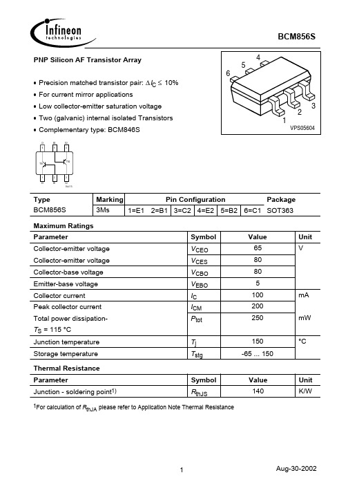
* Technical performance data acc. to IEC 60268-5 Mechanical
Dimensions (L x Dmax)
499 x 490 mm (20 x 19.6 in)
Weight
4.5 kg (9.9 lb)
LBC 3484/00 Electrical*
Maximum power
75 W
Rated power
50 / 25 / 12.5 W
Sound pressure level at 50 W / 1 W (1 kHz, 1 m)
127 dB / 110 dB (SPL)
Effective frequency range (-10 dB)
Color
Light gray (RAL 7035)
Cable diameter Environmental
6 mm to 12 mm (0.24 in to 0.47 in)
Operating temperature
-25 ºC to +55 ºC (-13 ºF to +131 ºF)
Storage and transport temperature
CE-label LBC3482/00
CE-label LBC3483/00
Bosch Security Systems B.V.
Installation note
2016.5 | V1.01 |
Bosch Security Systems B.V. Torenallee 49 5617 BA Eindhoven Netherlands © Bosch Security Systems B.V., 2016
PCA8565TS1,118;PCA8565BS1,118;中文规格书,Datasheet资料

1.General descriptionThe PCA8565 is a CMOS 1 real time clock and calendar optimized for low powerconsumption.A programmable clock output,interrupt output and voltage-low detector are also provided. All address and data are transferred serially via a two-line bidirectional I 2C-bus. Maximum bus speed is 400kbit/s. The built-in word address register is incremented automatically after each written or read data byte.AEC-Q100 compliant (PCA8565TS) for automotive applications.2.FeaturesI Provides year, month, day, weekday, hours, minutes and seconds based on a 32.768kHz quartz crystal I Century flagI Clock operating voltage: 1.8V to 5.5VI Extended operating temperature range:−40°C to +125°CI Low backup current; typical 0.65µA at V DD =3.0V and T amb =25°C I 400kHz two-wire I 2C-bus interface (at V DD =1.8V to 5.5V)I Programmable clock output for peripheral devices (32.768kHz,1.024kHz,32Hz and 1Hz)I Alarm and timer functions I Internal power-on resetI I 2C-bus slave address: read A3h and write A2h I Open-drain interrupt pinI One integrated oscillator capacitor3.ApplicationsI Automotive I IndustrialI Other applications that require a wide operating temperature rangePCA8565Real time clock/calendarRev. 02 — 16 June 2009Product data sheet1.The definition of the abbreviations and acronyms used in this data sheet can be found in Section 16.4.Ordering information5.Marking Table 1.Ordering informationType number PackageName Description Version PCA8565TS TSSOP8plastic thin shrink small outline package; 8 leads;body width 3 mmSOT505-1PCA8565BS HVSON10plastic thermal enhanced very thin small outlinepackage; no leads; 10 terminals;body 3×3× 0.85mmSOT650-1Table 2.Marking codesType number Marking codePCA8565TS8565PCA8565BS8565S6.Block diagramFig 1.Block diagram of PCA8565001aah661PCA8565OSCILLATOR 32.768 kHzDIVIDERCLOCK OUTINTERRUPTCLKOUTMONITORPOWER-ON RESETWATCH DOGI 2CINTERFACEOSCISCLSDA OSCOV DD V SSTIMER FUNCTIONTimer_control 0Eh Timer0FhCONTROL Control_100h Control_201h CLKOUT_control0DhTIMESeconds 02h Minutes 03hHours 04h Days 05h ALARM FUNCTIONMinute_alarm 09h Hour_alarm 0AhDay_alarm 0Bh Weekday_alarm0ChWeekdays 06h Months_century 07hYears 08hINT7.Pinning information7.1Pinning7.2Pin description[1]The die paddle (exposed pad) is wired to V SS but should not be electrically connected.Top view. For mechanical details see Figure 28.For mechanical details see Figure 29.Fig 2.Pin configuration of PCA8565TS (TSSOP8)Fig 3.Pin configuration of PCA8565BS (HVSON10)PCA8565TSOSCI V DD OSCO CLKOUT INT SCL V SSSDA001aaj75412346587001aaj753PCA8565BS SDAINT V SSSCL n.c.CLKOUT OSCO V DD OSCI n.c.Transparent top view56473829110terminal 1index areaTable 3.Pin descriptionSymbol Pin DescriptionTSSOP8HVSON10OSCI 11oscillator input OSCO 22oscillator outputn.c.-3, 10do not connect and do not use as feed through;connect to V DD if floating pins are not allowed INT 34interrupt output (open-drain; active LOW)V SS 45[1]ground SDA 56serial data I/O SCL 67serial clock input CLKOUT 78clock output, open-drain V DD89positive supply voltage8.Device protection diagram9.Functional descriptionThe PCA8565contains sixteen 8-bit registers with an auto-incrementing address register,an on-chip 32.768kHz oscillator with one integrated capacitor, a frequency divider which provides the source clock for the Real Time Clock (RTC),a programmable clock output,a timer, an alarm, a voltage-low detector and a 400kHz I 2C-bus interface.All 16registers are designed as addressable 8-bit registers although not all bits are implemented:•The first two registers (memory address 00h and 01h)are used as control and statusregisters•The registers at memory addresses 02h through 08h are used as counters for theclock function (seconds up to years counters)•Address locations 09h through 0Ch contain alarm registers which define theconditions for an alarm•The register at address 0Dh controls the CLKOUT output frequency•At address 0Eh is the timer control register and address 0Fh contains the timer valueThe arrays SECONDS, MINUTES, HOURS, DAYS, WEEKDAYS, MONTHS, YEARS as well as the bit fields MINUTE_ALARM, HOUR_ALARM, DAY_ALARM and WEEKDAY_ALARM are all coded in Binary Coded Decimal (BCD) format.When one of the RTC registers is read the contents of all time counters are frozen. This prevents faulty reading of the clock or calendar during a carry condition (see Section 10.5.3).Fig 4.Device diode protection diagram of PCA8565mce169SDAV SS SCLINTCLKOUTOSCO V DDOSCIPCA85659.1Register overviewTable 4.Register overview and control bits default valuesBit positions labeled as- are not implemented. Bit positions labeled as N should always be written with logic0. Reset values are shown in Table7.Address Register name Bit76543210 Control registers00h Control_1TEST1N STOP N TESTC N N N01h Control_2N N N TI_TP AF TF AIE TIE Time and date registers02h Seconds VL SECONDS (0 to 59)03h Minutes-MINUTES (0 to 59)04h Hours--HOURS (0 to 23)05h Days--DAYS (1 to 31)06h Weekdays-----WEEKDAYS (0 to 6)07h Months_century C--MONTHS (1 to 12)08h Y ears YEARS (0 to 99)Alarm registers09h Minute_alarm AE_M MINUTE_ALARM (0 to 59)0Ah Hour_alarm AE_H-HOUR_ALARM (0 to 23)0Bh Day_alarm AE_D-DAY_ALARM (1 to 31)0Ch Weekday_alarm AE_W----WEEKDAY_ALARM (0 to 6) CLKOUT control register0Dh CLKOUT_control FE-----FDTimer registers0Eh Timer_control TE-----TD0Fh Timer COUNTDOWN_TIMER9.2Control registers9.2.1Register Control_1Table 5.Register Control_1 (address00h) bits descriptionBit Symbol Value Description7TEST10[1]normal mode1EXT_CLK test mode6N0[2]default value5STOP0[1]RTC source clock runs1all RTC divider chainflip-flops are asynchronously set tologic0;the RTC clock is stopped(CLKOUT at32.768kHz is stillavailable)4N0[2]default value3TESTC0power-on reset override facility is disabled;set to logic0 for normal operation1[1]power-on reset override may be enabled2to0N000[2]default value[1]Default value.[2]Bits labeled as N should always be written with logic 0.9.2.2Register Control_2Table 6.Register Control_2 (address01h) bits descriptionBit Symbol Value Description7to5N000[1]default value4TI_TP0[2]INT is active when TF is active (subject to the status ofTIE)1INT pulses active according to T able26 (subject to thestatus of TIE);Remark:note that if AF and AIE are active then INT willbe permanently active3AF0[2]alarm flag inactive1alarm flag active2TF0[2]timer flag inactive1timer flag active1AIE0[2]alarm interrupt disabled1alarm interrupt enabled0TIE0[2]timer interrupt disabled1timer interrupt enabled[1]Bits labeled as N should always be written with logic 0.[2]Default value.9.3ResetThe PCA8565 includes an internal reset circuit which is active whenever the oscillator is stopped.In the reset state the I2C-bus logic is initialized including the address pointer.All other registers are set according to Table7.Table 7.Register reset values[1]Address Register name Bit76543210 00h Control_10000100001h Control_2x x00000002h Seconds1x x x x x x x03h Minutes1x x x x x x x04h Hours x x x x x x x x05h Days x x x x x x x x06h Weekdays x x x x x x x x07h Months_century x x x x x x x x08h Y ears x x x x x x x x09h Minute_alarm1x x x x x x x0Ah Hour_alarm1x x x x x x x0Bh Day_alarm1x x x x x x x0Ch Weekday_alarm1x x x x x x x0Dh CLKOUT_control1x x x x x000Eh Timer_control0x x x x x110Fh Timer x x x x x x x x[1]Registers labeled ‘x’ are undefined at power-on and unchanged by subsequent resets.9.4Time and date registersThe majority of the registers are coded in the BCD format to simplify application use.Table 8.Register Seconds (address02h) bits descriptionBit Symbol Value Place value Description7VL0-clock integrity is guaranteed1[1]-integrity of the clock information is not guaranteed 6to4SECONDS0to5[2]ten’s place actual seconds coded in BCD format3 to 00 to 9[2]unit place[1]Start-up value.[2]Values shown in decimal.[1]Values shown in decimal.[1]Values shown in decimal.[1]The PCA8565 compensates for leap years by adding a 29th day to February if the year counter contains a value which is exactly divisible by 4, including the year 00.[2]Values shown in decimal.[1]Values shown in decimal.Table 9.Seconds coded in BCD formatSeconds value in decimal Upper-digit (ten’s place)Digit (unit place)Bit 6Bit 5Bit 4Bit 3Bit 2Bit 1Bit 0000000000010000001020000010:090001001100010000:581011000591111Table 10.Register Minutes (address 03h) bits descriptionBit Symbol Value Place value Description 7---unused6to 4MINUTES0to 5[1]ten’s place actual minutes coded in BCD format3 to 00 to 9[1]unit placeTable 11.Register Hours (address 04h) bits descriptionBit SymbolValue Place value Description 7 to 6---unused5to 4HOURS 0to 2[1]ten’s place actual hours coded in BCD format3 to 00 to 9[1]unit placeTable 12.Register Days (address 05h) bits descriptionBit SymbolValue Place value Description 7 to 6---unused5to 4DAYS [1]0to 3[2]ten’s place actual day coded in BCD format3 to 00 to 9[2]unit placeTable 13.Register Weekdays (address 06h) bits descriptionBit SymbolValue Description 7 to 3--unused2to 0WEEKDAYS0to 6[1]actual weekday values, see Table 14[1]Definition may be re-assigned by the user.[1]This bit may be re-assigned by the user.[2]This bit is toggled when the years register overflows from 99 to 00.[3]Values shown in decimal.Table 14.Weekday assignmentsDay [1]Bit 210Sunday 000Monday 001T uesday010Wednesday 011Thursday 100Friday 101Saturday11Table 15.Register Months_century (address 07h) bits descriptionBit SymbolValue Place value Description 7C [1]0[2]-indicates the century is x 1-indicates the century is x +16 to 5---unused4MONTHS0to 1[3]ten’s place actual month coded in BCD format, see Table 163 to 00 to 9[3]unit placeTable 16.Month assignments coded in BCD formatMonthUpper-digit (ten’s place)Digit (unit place)Bit 4Bit 3Bit 2Bit 1Bit 0January 00001February 00010March 00011April 00100May 00101June 00110July 00111August 01000September 01001October 10000November 10001December11分销商库存信息:NXPPCA8565TS/1,118PCA8565BS/1,118。
851-566 Rev. B Multi Tier Stands产品说明书
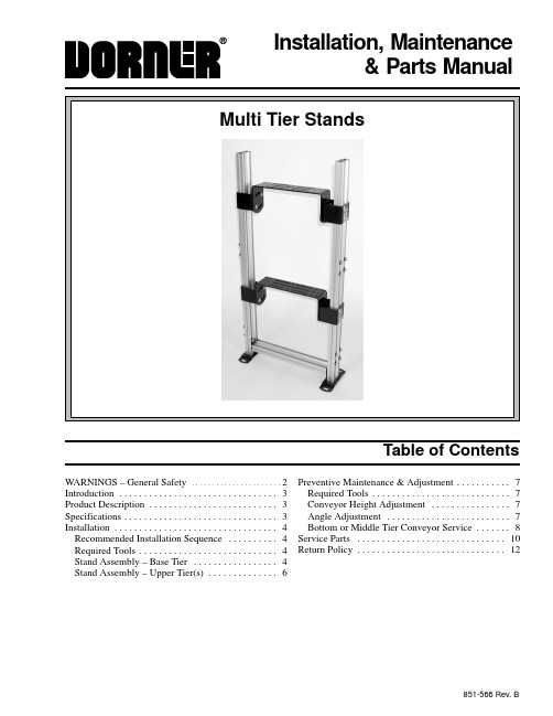
Installation, Maintenance& Parts ManualTable of ContentsWARNINGS – General Safety2. . . . . . . . . . . . . . . . . . . . . . Introduction3 . . . . . . . . . . . . . . . . . . . . . . . . . . . . . . . .Product Description3. . . . . . . . . . . . . . . . . . . . . . . . . .Specifications3. . . . . . . . . . . . . . . . . . . . . . . . . . . . . . .Installation4 . . . . . . . . . . . . . . . . . . . . . . . . . . . . . . . . . Recommended Installation Sequence4. . . . . . . . . . Required Tools4. . . . . . . . . . . . . . . . . . . . . . . . . . . . Stand Assembly – Base Tier4. . . . . . . . . . . . . . . . . Stand Assembly – Upper Tier(s)6. . . . . . . . . . . . . . Preventive Maintenance & Adjustment7. . . . . . . . . . . Required Tools7. . . . . . . . . . . . . . . . . . . . . . . . . . . . Conveyor Height Adjustment7. . . . . . . . . . . . . . . . Angle Adjustment7. . . . . . . . . . . . . . . . . . . . . . . . . Bottom or Middle Tier Conveyor Service8. . . . . . . Service Parts10. . . . . . . . . . . . . . . . . . . . . . . . . . . . . . Return Policy12. . . . . . . . . . . . . . . . . . . . . . . . . . . . . .851-566 Rev. BMulti Tier Aluminum Support Stands Installation, Mantenance & Parts Manual851-566 Rev. B2Dorner Mfg. Corp.Warnings - General SafetyMulti Tier Aluminum Support Stands Installation, Mantenance & Parts ManualDorner Mfg. Corp.3851-566 Rev. BIMPORTANT : Some illustrations may show guardsremoved. Do NOT operate equipment without guards.Upon receipt of shipment:D Compare shipment with packing slip. Contact factory regarding discrepancies.D Inspect packages for shipping damage. Contact carrier regarding damage.D Accessories may be shipped loose. See accessory in-structions for installation.Dorner’s Limited Warranty applies.Dorner reserves the right to make changes at any time without notice or obligation.Product DescriptionRefer to Figure 1 for typical stand components.A Tube End CoversB Tier LegsC Leg Support BracketsD Stand LegsE Base AssemblyFConveyor Mounting BracketsTypical ComponentsFigure 1SpecificationsMulti Tier Support Stand ModelsStand Leg Length – 12” (305mm) (Base Tier)Tier Leg Length – 6” (152mm) (Upper Tier)From Floor to Top of Stand Leg* (Base Tier)From Joint to Top of Tier Leg* (Upper Tier)Example: 39MT112–1260Base Tier of Multi Tier, H style stand for a 12” (305mm) wide conveyor with a lower height of 12” (305mm) and an upper height of 60” (1524mm). The base tier comes partially assembled and has U.S. English documentation.WWLHUpper TierWW* When raised to its maximum height, top of conveyor mounting bracket (F of Figure 1) is at the same height as top of stand leg (D) (base tier) or tier leg (B)(upper tier).IntroductionMulti Tier Aluminum Support Stands Installation, Mantenance & Parts Manual851-566 Rev. B4Dorner Mfg. Corp.Recommended Installation Sequence (see Table of Contents for page number)D Assemble base tierD Install bottom conveyor on base tier D Assemble middle tierD Attach middle tier to base tier Install middle conveyor Assemble top tierAttach top tier to middle tier Install top conveyorAdjust stand height and angle (see Preventative Figure 2J orOpen tier hardware pack (M of Figure 2). Install twohard washers (O of Figure 3) and M8 x 12mm socket head screws (P) on tube joining bar (N). Do not tighten screws.OPFigure 3OPNRepeat step 2 for three remaining tube joining bars.Failure to secure tier joint screws (P of Figures 4 and 6)may cause tube joining bar and conveyor sections to drop down, causing severe injury.TIGHTEN ALL TIER JOINT SCREWS (P) AFTER INSTALLATION.InstallationMulti Tier Aluminum Support Stands Installation, Mantenance & Parts ManualDorner Mfg. Corp.5851-566 Rev. B4.Install tube joining bar assembly (O of Figure 4) attop of leg on base assembly (J). Half of tube joining bar assembly must extend above leg, as shown.Tighten screw (P) to 130 in–lbs (15 Nm).Figure 45.Repeat step 4 for three remaining tube joining barassemblies.6.Slide stand leg (I of Figure 5) over both tube joiningbars (N) until it is resting on leg of base assembly (J).Figure 57.Tighten screws (P of Figure 6) to 130 in–lbs (15Nm).Figure 6P8.Repeat steps 6 and 7 for other stand leg.NOTE: Leg support bracket (H of Figure 7) must beinstalled on stand/conveyor mounting bracket(s) (G)with warning label (Q) facing out. When installed,round end of stand/conveyor mounting bracket will be down and warning label will be upright, as shown.9.Attach leg support bracket (H of Figure 7) tostand/conveyor mounting bracket (G) with two flange socket head screws (R). Do not tightenscrews.Figure 710.Repeat step 9 for opposite leg support bracket (H ofFigure 7). To ensure proper attachment of stand/con-veyor mounting bracket to conveyor, install flange socket head screws (R) in opposite holes on opposite leg support bracket, as shown.11.Install two M10 x 16mm button head screws (S ofFigure 8) and hex nuts (T) on leg support bracket(H). Do not tighten screws.Figure 812.Repeat step 11 for other leg support bracket.InstallationMulti Tier Aluminum Support Stands Installation, Mantenance & Parts Manual851-566 Rev. B6Dorner Mfg. Corp.13.Align two hex nuts (T of Figure 9) on each legsupport bracket (H) to t–slots at top, outside of stand legs (I). Slide leg support brackets down stand legs until top of stand/conveyor mounting bracket (G) is approximately the same height as the bottom of conveyor. Tighten four button head screws (S) justenough to keep leg support brackets in position.Figure 914.Installconveyor on base tier. See Conveyor Installa-tion, Maintenance and Parts Manual for installation instructions.15.Tighten four flange socket head screws (R of Figure10) to 24 ft–lb (33 N–m).16.Tighten four button head screws (S of Figure 10) to17 ft–lb (22.5 N–m).Figure 10RS17.Make height and angle adjustments as required . See“Conveyor Height Adjustment” section on page 7.See “Angle Adjustment” section on page 7.Stand Assembly – Upper Tier(s)1.For assembly of upper tier(s) on multi tier stand,repeat steps 2 through 17 for “Stand Assembly –Base Tier” starting on page 4.2.Attach tube end cover (K of Figure 11) on stand leg(I) with two plastic tree rivets (L).Figure 11KLI3.Repeat step 2 for opposite stand leg.InstallationMulti Tier Aluminum Support Stands Installation, Mantenance & Parts ManualDorner Mfg. Corp.7851-566 Rev. BRequired ToolsD 6 mm Hex Key Wrench D LevelConveyor Height Adjustment1.Install a support (Uof Figure 12) below conveyor (V)that will be adjusted.Figure 12IUVRSW2.Loosen two flange socket head screws (R of Figure 12)on each side of conveyor (V).3.Loosen two button head screws (S) on each side ofconveyor (V).4.Adjust conveyor to desired height. Using a level(W), ensure conveyor is level from side to side.5.Tighten two flange socket head screws (R of Figure12) on each side of conveyor (V) to 24 ft-lb (33 N–m).6.Tighten twobutton head screws (S) on each side ofconveyor (V) to 17 ft-lb (22.5 N–m).Angle AdjustmentNOTE: T o rotate conveyor mounting bracket (G of Fig-ure 13), it may need necessary to relocated screws (R)to holes (X).1.Loosen angle adjustment screws (R of Figure 13) onboth sides of conveyor.Figure 13RXGPreventive Maintenance and AdjustmentMulti Tier Aluminum Support Stands Installation, Mantenance & Parts Manual851-566 Rev. B8Dorner Mfg. Corp.2.Adjust conveyor to desired angle. Using a level (Wof Figure 12), ensure conveyor is level from side toside.3.Tighten angle adjustment screws (R) to 24 ft-lb (33N–m).Bottom or Middle Tier Conveyor Service1.Near the multi teir stand, support the conveyor to beserviced AND the conveyor directly above.2.Remove two flange socket head screws (R of Figure14) from the conveyor to be serviced.Figure 143.Loosen eight screws (P of Figure 15).Figure 15PP4.Slide four tube joining bar assemblies (O of Figure16) out of the way. Remove stand section (Y) and leg support bracket (H) from multi tier stand.Figure 16YOOH5.Perform maintenance as required on conveyor.6.Reverse steps to reinstall stand section (Y) and legsupport bracket (H) on multi tier stand when service is complete.7.Tighten eight screws (P of Figure 15) to 130 in–lbs(15 N–m) and two flange socket head screws (R of Figure 14) to 24 ft-lb (33 N–m).Preventive Maintenance and AdjustmentNotes Multi Tier Aluminum Support Stands Installation, Mantenance & Parts ManualDorner Mfg. Corp.9851-566 Rev. BMulti Tier Aluminum Support Stands Installation, Mantenance & Parts Manual851-566 Rev. B10Dorner Mfg. Corp.NOTE: For replacement parts other than those shown on this page, contact an authorized Dorner Service Center or the factory.Multi Tier Stand61821110973541213141511or181716918Item Part Number Description1202148Brkt, Mtg., Conv 12” (305mm) Wide 200697Brkt, Mtg., Conv 14”–48” (356 –1219mm) Wide (2x)2807–1289Rivet, Tree, 0.22 Dia. x 0.75 Long 3710003Cover, Tube End, Stand 4710016Bracket, Leg Support5See Stand LegTable Leg, Multi Tier Stand6710041Bar, Joining, Tubes 7710004Foot, Stand, Floor Mtg.8708180PScr, Sock, Metric M6–1.00x25MM9991001M Nut, Hex, Full M10–1.5010710006Plate, End, Crossmember 11911016M Scr, Bttn, Metric M10–1.50x16MM 12See Cross-member Table Crossmember13710213–00554Leg, Base, Multi Tier Stand14605280P Washer, Hard, .361X.750X.12015920812M Scr, Sock, Metric M8–1.25x12MM 16920883M Scr, Flange, Socket M8–1.25x16MM 17300324PLabel, Warning, Overhead Hazard18See Stand TierLeg TableLeg, Tier, Multi Tier StandService PartsMulti Tier Aluminum Support Stands Installation, Mantenance & Parts ManualDorner Mfg. Corp.11851-566 Rev. BItem 5: Stand Leg Base Upper Height Part Number 12” (305mm)710211–0060014” (356mm)710211–0080016” (406mm)710211–0100018” (457mm)710211–0120020” (508mm)710211–0180022” (559mm)710211–0200024” (610mm)710211–0220026” (660mm)710211–0240028” (711mm)710211–0260030” (762mm)710211–0280032” (813mm)710211–0300034” (864mm)710211–0320036” (914mm)710211–0340038” (965mm)710211–0360040” (1016mm)710211–0380042” (1067mm)710211–0400044” (1118mm)710211–0420046” (1168mm)710211–0440048” (1219mm)710211–0460050” (1270mm)710211–0480052” (1321mm)710211–0500054” (1372mm)710211–0520056” (1422mm)710211–0540058” (1473mm)710211–0560060” (1524mm)710211–05800Item 12: Crossmember Conveyor Width Part Number 2–12”(51–305mm)710210–0169114” (356mm)710210–0189116” (406mm)710210–0209118” (457mm)710210–0229120” (508mm)710210–0249122” (559mm)710210–0269124” (610mm)710210–0289126” (660mm)710210–0309128” (711mm)710210–0329130” (762mm)710210–0349132” (813mm)710210–0369134” (864mm)710210–0389136” (914mm)710210–0409138” (965mm)710210–0429140” (1016mm)710210–0449142” (1067mm)710210–0469144” (1118mm)710210–0489146” (1168mm)710210–0509148” (1219mm)710210–05291Item 18: Tier Leg Tier Upper Height Part Number 12” (305mm)710211–0120013” (330mm)710211–0130014” (356mm)710211–0140015” (381mm)710211–0150016” (406mm)710211–0160017” (432mm)710211–0170018” (457mm)710211–0180019” (483mm)710211–0190020” (508mm)710211–0200021” (533mm)710211–0210022” (559mm)710211–0220023” (584mm)710211–0230024” (610mm)710211–0240025” (635mm)710211–0250026” (660mm)710211–0260027” (686mm)710211–0270028” (711mm)710211–0280029” (737mm)710211–0290030” (762mm)710211–0300031” (787mm)710211–0310032” (813mm)710211–0320033” (838mm)710211–0330034” (864mm)710211–0340035” (889mm)710211–0350036” (914mm)710211–03600Service PartsReturn PolicyFor replacement parts, contact an authorizedDorner Service Center or the factory.851-566 Rev. B Printed in U.S.A.。
DS1688S;DS1691;DS1688;DS1688S+;中文规格书,Datasheet资料
+ Denotes a lead(Pb)-free/RoHS-compliant device. + A “+” anywhere on the top mark denotes a lead(Pb)-free/RoHS-compliant device.
1 of 3
REV: 112205
/
PIN-PACKAGE 28 SO (0.330) 28 SO (0.330) 28 EDIP (0.740) TOP MARK* DS1688S DS1688S DS1691
N CONFIGURATIONS
TOP VIEW
ORDERING INFORMATION
PART DS1688S DS1688S+ DS1691 TEMP RANGE 0C to +70C 0C to +70C 0C to +70C VOLTAGE (V) 3 to 5 3 to 5 3 to 5
DS1688/DS1691
DETAILED DESCRIPTION
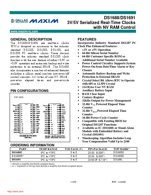
Each DS1688/DS1691 is individually manufactured with a unique 64-bit serial number as well as an additional 64-bit customer-specific ROM or serial number. The serial number is programmed and tested at Dallas to ensure that no two devices are alike. The serial number can be used to electronically identify a system for purposes such as establishment of a network node address or for maintenance tracking. Customers can reserve blocks of available numbers from Dallas Semiconductor. The serialized RTCs also incorporate power-control circuitry, which allows the system to be powered on via an external stimulus, such as a keyboard or by a time and date (wake up) alarm. The PWR output pin can be triggered by one or either of these events, and can be used to turn on an external power supply. The PWR pin is under software control, so that when a task is complete, the system power can then be shut down. The DS1688/DS1691 incorporate a power-on elapsed time counter, a power-on cycle counter, and a battery powered continuous counter. These three counters provide valuable information for maintenance and warranty requirements. Automatic backup and write protection for an external SRAM is provided through the VCCO and CEO pins. The lithium energy source used to permanently power the RTC is also used to retain RAM data in the absence of VCC power through the VCCO pin. The chip enable output to RAM (CEO) is controlled during power transients to prevent data corruption. The DS1688 is a clock/calendar chip with the features described above. An external crystal and battery are the only components required to maintain time-of-day and memory status in the absence of power. The DS1691 incorporates the DS1688 chip, a 32.768kHz crystal, and a lithium battery in a complete, selfcontained timekeeping module. The entire unit is fully tested at Dallas Semiconductor such that a minimum of 10 years of timekeeping and data retention in the absence of VCC is guaranteed. For a complete description of operating conditions, electrical characteristics, bus timing, and pin descriptions other than the SQW output, refer to the DS1689/DS1693 data sheet, available online at /DS1689.
BCM856S中文资料
10 1
0.5
0.2
0.1
0.05
0.02
10 0
0.01
0.005
D=0
Ptotmax/PtotDC
00
20 40 60 80 100 120 °C 150
TS
Permissible Pulse Load
Ptotmax/PtotDC = (tp)
10 3 -
D=0
10 2
0.005
0.01
h12e h21e
-
2
-
-
330
-
Open-circuit output admittance IC = 2 mA, VCE = 5 V, f = 1 kHz Noise figure
h22e
-
30
-
F
-
-
10
IC = 200 µA, VCE = 5 V, f = 1 kHz,
f = 200 Hz, RS = 2 k
1
VBE
5
Aug-30-2002
元器件交易网
BCM856S
DC current gain hFE = (IC)
VCE = 5V
Output characteristics IC = (VCE),
IB = parameter
10 3 h FE 5 100 C
25 C 102 -50C
5
EHP00382
10 1 5
10 0 10 -2
5 10 -1 5 10 0
5 101 mA 10 2 ΙC
Collector cutoff current ICBO = (TA)
VCBO = 30 V
超高速同步采集卡说明书PCIE8511H
PCIE8511 同步采集卡硬件使用说明书阿尔泰科技发展有限公司产品研发部修订阿尔泰科技发展有限公司目录目录 (1)第一章概述 (2)第一节、产品应用 (2)第二节、AD模拟量输入功能 (2)第三节、产品安装核对表 (3)第四节、安装指导 (3)第二章元件布局图及简要说明 (4)第一节、主要元件布局图 (4)第二节、主要元件功能说明 (4)第三章信号输入输出连接器 (5)第四章各种信号的连接方法 (7)第一节、AD模拟量输入的信号连接方法 (7)第二节、时钟输入输出和触发信号连接方法 (7)第三节、多卡同步的实现方法 (7)第五章数据格式、排放顺序及换算关系 (10)第一节、AD模拟量输入数据格式及码值换算 (10)第二节、AD多通道采集时的数据排放顺序 (10)第六章各种功能的使用方法 (12)第一节、AD触发功能的使用方法 (12)第二节、AD内时钟与外时钟功能的使用方法 (15)第三节、软件自动校准 (16)第七章产品的应用注意事项、校准、保修 (17)第一节、注意事项 (17)第二节、AD模拟量输入的校准 (17)第三节、保修 (17)PCIE8511同步采集卡硬件使用说明书版本:V6.00.00第一章概述信息社会的发展,在很大程度上取决于信息与信号处理技术的先进性。
数字信号处理技术的出现改变了信息与信号处理技术的整个面貌,而数据采集作为数字信号处理的必不可少的前期工作在整个数字系统中起到关键性、乃至决定性的作用,其应用已经深入到信号处理的各个领域中。
实时信号处理、数字图像处理等领域对高速度、高精度数据采集卡的需求越来越大。
ISA总线由于其传输速度的限制而逐渐被淘汰。
我公司推出的PCIE8511数据采集卡综合了国内外众多同类产品的优点,以其使用的便捷、稳定的性能、极高的性价比,获得多家试用客户的一致好评,是一款真正具有可比性的产品,也是您理想的选择。
第一节、产品应用PCIE8511卡是一种基于USB总线的数据采集卡,可直接和计算机的USB接口相连,构成实验室、产品质量检测中心等各种领域的数据采集、波形分析和处理系统。
BlueBird Turf Products SC550A 968999351 配件手册说明书
Parts ManualModelsSC550A/968999351Please read the operator’s manual carefully and make sure you understand the instructions before using the machine.©2017 BlueBird Turf Products All rights reserved.CONTENTSNOTE: ALL FASTENERS ARE GRADE 5 UNLESS OTHERWISE SPECIFIED.FRAME ........................................................................4HANDLE .....................................................................6DRIVE .........................................................................8BLADE DRIVE ...........................................................10DEPTH CONTROL . (12)GEARS ......................................................................14TRUNNION ...............................................................16AXLE .........................................................................18DECALS .. (20)4FRAME134578910111262101010ITEM PART QTY.NO. DESCRIPTION ITEM PART NO. QTY. DESCRIPTIONFRAME1.. 576228001.....1...CHASSIS3..539112861.....2...NUT PLATE4..539112899.....4...NUT5/16-18 FLG NYLOC5..539112836.....1...FRONT WEIGHT6. 576227801.....1...COVER, TOP7 ..576228301.....1...COVER, SHIFT8.. 576227901.....1...BELLY PAN9.. 576228201.....1...END BRACKET10..539990362...17...SCREW ¼-20 x5/8SELF TAP11..539990563.....4...HCS3/8-16 x 112..539976979.....4...NUT3/8-16 HEX NYLOCNOT SHOWN505155501 1 SWITCH TOGGLEGROUNDING56HANDLE123457891011121314151617186ITEM PART QTY.NO. DESCRIPTION ITEM PART NO. QTY. DESCRIPTIONHANDLE1..539030452.....2.. MOUNT2..539030468.....2...BUSHING, POLYURETHANE3..539990669.....4...HCS5/16-18 x 1¾4..539990717.....4...NUT5/16-18 HEX NYLOC5..539108519.....6...HCS M8-1.25 x 22, GR 8.86..539112870.....2...CLIP, CABLE7..539109867.....1...TUBE CLAMP, DOUBLE8..576228101.....1...HANDLE9..539113222.....1...ROLL PIN5/16DIA x 1½10..539113220.....1...LEVER, THROTTLE, BLK11..539113223.....1...PIN CLEVIS12..539113221.....1...CABLE, PULL13..539990037.....1...PIN COTTER3/32x ¾14..539990585.....2...NUT5/16-18 WHIZLK15..539990209.....1...HCS5/16-18 x 116..539000090.....2...GRIP, HANDLE17..539101050.....1...GRIP, VINYL18..539113454.....2...STAND OFF7DRIVE8ITEM PART QTY.NO. DESCRIPTION ITEM PART NO. QTY. DESCRIPTIONDRIVE1..539112855.....1...IDLER,PIVOT2..539112869.....1... IDLER,ARM,BELT3..539112868.....1...ARM, IDLER, CHAIN4..539112854.....1...TRANSMISSION, 4 SPEED5..539112463.....1...PULLEY, 5.25 A6..539112825.....1...SPACER, PTO SHAFT7..539112464.....1...PULLEY, 3.75 A8..539000343.....1...PULLEY IDLER9..539030440.....1...SPROCKET, ENGINE10..539030456.....1...SPROCKET #40 CHAIN11..539030429.....1...SPROCKET,TRANS12..539003133.....1...CHAIN TENSIONER13..539030430.....1...SPROCKET14..539109216.....1...PIN CLEVIS ½ x 315..539108619.....2...BUSHING16..539101151.....1...RETAINING RING17..539990730.....1...HCS3/8-18 x 1¾18..539200282.....1...NUT3/8-16 HAM NYLOC19..539109159.....1...KEY 7mm SQ x 33mm20..539112826.....1...WASHER, STEPPED21..539112859.....1...HCS M8-1.25 x 55 GR 8.822..539990717.....1...NUT5/16-18 NYLOC23..539109246.....1...PIN COTTER1/8x 124..539910008.....1...KEY WOODRUFF #625..539977748.....1...HCS3/8-24 x ¾26..539113455.....1...SPRING ANCHOR27..539109984.....1...RING9/16RETAINING, EXT28..539101971.....1...RETAINING RING 29..539910211.....1...KEY, WOODRUFF #930..539112833.....1...SPROCKET, TENSIONER 3531..539976979.....1...NUT3/8-16 NYLOC32..539990250.....1...WASHER ½ SAE33..539990187.....8...WASHER5/16SLW34..539976934.....5...HCS5/16-18 x ¾35..539990188.....4...WASHER5/16SAE36..539030445.....1...SPRING, THROTTLE37..539030449.....1...CLAMP, THROTTLE CABLE38..539030451.....1...E-RING CLIP, THROTTLE39..539108520.....1...HCS M5-0.8 x 16 GR 8.840..539109154.....1...NUT 5mm-841..539030439.....1...V-BELT42..539108583.....1...SCREW #8-32 x ¼43..539990118.....3...WASHER3/8SPLT LOCK44..539990546.....1...NUT3/8-16 CNTRLK45..539108735.....2...NUT ¼-20 FLANGE LK46..539100266.....1...HCS ¼-20 x 1¼47..539100567.....2...HCS M8-1.25 x 30 GR 8.848..539990669.....4...HCS5/16-18 x 1¾49..539112483.....1...WASHER3/8SPRING50..539100145.....1...RHSNB3/8-16 x 251..539007203.....2...PLATE, ENGINE52..539010195.....1...SPRING53..539113180.....1...KEEPER, CHAINNOT SHOWN539030443....1...CHAIN, TRANSMISSION #35539112875....1...CHAIN, WHEELS #409BLADE DRIVE10ITEM PART QTY.NO. DESCRIPTION ITEM PART NO. QTY. DESCRIPTIONBLADE DRIVE1..539030455.....1...GEAR BOX2..539102677.....4...BEARING3..539112465.....2...LINK, CONNECTING4..539113449.....1...BLADE KIT, 18"5..539112471.....1...SHAFT, BLADE ARM6..539112879.....2...SPRIAL PIN ¼ x 1¼7..539112484.....4...SPRING WASHER ½8..539106776.....2...HCS3/8-16 x ½9..539990646.....2...HCS ½-13 x 110..539976979.....8...NUT3/8-16 NYLOC11..539112483.....2...SPRING WASHER3/812..539112850.....1...STRAP, T BOX 13..539990591.....2...HCS3/8-16 x 4½14..539977670.....2...HCS3/8-24 x 1¾ GR 815..539990155.....2...NUT3/8-24 GR216..539112872.....2...ECCENTRIC17..539910211.....2...KEY, WOODRUFF #918..539112873.....1...BLADE ARM, RH19..539112874.....1...BLADE ARM, LH20..539990289.....2...NUT3/8-24 CTR LK21..539976935.....2...HCS5/16-18 x 1½22..539112482.....4...SNAP RING 52mm23..539130628.....6...HCS3/8-16 x 1¼ GR 824..539990122.....2...WASHER3/8SAE11Bushing is weldedITEM PART QTY.NO. DESCRIPTION ITEM PART NO. QTY. DESCRIPTIONDEPTH CONTROL1..505162702.....1...SHAFT2..539000090.....1...GRIP, HANDLE3..539112895.....2...BEARING, FLANGE4..539112496.....2...SNAP RING ¾5..539976979.....3...NUT3/8-16 NYLOC6..539976980.....1...NUT5/8-187..539976935.....1...HCS5/16-18 x 1½8..539990717.....1...NUT5/16NYLOC9..539102827.....1...SPACER, PULLEY10..539990585.....1...NUT5/16WHIZLK11..539976934.....1...HCS5/16-18 x ¾12..539112843.....1...HANDLE13..539990730.....2...HCS3/8-16 x 1¾14..539990517.....7...WASHER3/815..539990629.....1...HCS3/8-16 x 2¼16..539112894.....1...ADJUSTER17..539113244.....1...ADJUSTER, RH18..539113176.....1...PLATE-ADJUSTER NUT19..539990598.....2...WASHER ¼20..539976978.....2...NUT ¼-20 NYLOC21..539112899...11...NUT5/16-18 FLANGE NYLOC22..539990548.....2...HCS ¼-20 x 124. 522031901.....1...KNOB W HIH TENSILE STUD25..539101050.....1...GRIP, VINYL1314GEARS1234578911121314151617181920212262112511141017ITEM PART QTY.NO. DESCRIPTION ITEM PART NO. QTY. DESCRIPTIONGEARS1..539112852.....1...SHIFT ROD2..539112851.....1...SHIFT LEVER3..539112490.....1...SHAFT, SHIFT PIVOT4..539100526.....1...SPACER5..539030425.....2...ROD END6..539003136.....1... BELL CRANK7..539102590.....1...BALL END, RH8..539030423.....1...ROD END5/16MALE9..539003135.....1...SHIFT ARM10..539112877.....1...KNOB, SHIFT11..539990692.....2...WASHER5/1612..539976941.....2...HCS3/8-16 x 1¼13..539976979.....1...NUT3/8-16 NYLOC14..539990155.....2...NUT3/8-24 GR215..539102754.....1...HCS3/8-16 x 3½ GR 816..539990546.....1...NUT3/8-16 CNTRLK17..539976934.....2...HCS5/16-18 x ¾18..539000407.....1...WASHER ¼ INT TOOTH LK19..539990055.....1...WASHER ¼ SAE20..539990100.....1...HCS ¼-28 x5/821..539109758.....2...NUT5/16-24 TOP LK GRC22..539109332.....1...NUT3/8-16 JAM15TRUNNION12345 7891011121314151617181920216861039 205471212A16ITEM PART QTY.NO. DESCRIPTION ITEM PART NO. QTY.TRUNNION1..539112834.....1...TRUNNION2..539130624.....1...PIN, CABLE PIVOT3..539112478.....2...BEARING ¾ 2 BOLT4..539109333.....4...WASHER ¾ SAE5..539108438.....2...HCS ¾-16 x 2½6..539110800.....2...NUT ¾-16 TOP LK7..539990209.....4...HCS5/16-18 x 18..539990717.....4...NUT5/16-18 NYLOC9..539976941.....4...HCS3/8-16 x 1¼10..539976979.....4...NUT3/8-16 NYLOC11..539109246.....1...PIN COTTER1/8x 112..539000316.....4...FLANGE ¾12A. 539000315......2....BEARING13..539113377.....1...SPRING EXTENSION14..539100032.....1...BUSHING, FLANGED15..539130625.....1...CABLE, PULL16..539976978.....1...NUT ¼-20 NYLOC17..539030464.....1...PULLEY BRACKET18..539112896.....1...J-BOLT19..539976982.....1...WASHER5/8SAE20..539990585.....2...NUT5/16-18 WHIZLK21..539113185.....2...SPRING, EXTENSIONDESCRIPTION17AXLE1234578967B18ITEM PART QTY.NO. DESCRIPTION ITEM PART NO. QTY. DESCRIPTIONAXLE1..539112823.....2...AXLE2..540030426.....4...WHEEL3..539000303.....2...SPROCKET w KEY4..539105308.....2...KEY ¼ SQ x 15..539976956.....8...KPSS5/16-18 x3/86..539990717.....8...NUT5/16-18 NYLOC7..539000318.....8...BEARING FLANGE7B..539000317... 4...BEAR I NG 1 INCH8..539976934.....8...HCS5/16-18 x ¾9..539113453.....4...SPIRAL PIN ¼ x 1½1920DECALS13576ITEM PART QTY.NO. DESCRIPTION ITEM PART NO. QTY. DESCRIPTIONDECALS1..539112881.....1...DECAL, SHIFT2..539101881.....1...DECAL, PROP 653..540200025.....1...DECAL, 3000 MAX RPM4..540200076.....1...DECAL, DANGER FOOT5..539112888.....1...DECAL, DEPTH OF CUT6..539112886.....1...DECAL, OPERATION7..539113238.....1...DECAL, SC550 SOD CUTTER8..539111041.....1...DECAL, BLUEBIRDNOT SHOWN539008340....1...DECAL, STACKED LOGO21P/N 115 370827R M 9/20/17BlueBird Turf Products68 S Squirrel RdAuburn Hills Mi 48326。
斑马技术公司DS8108数字扫描仪产品参考指南说明书
DSEI60-06A;中文规格书,Datasheet资料
166 W
0.8...1.2 Nm
6
g
Symbol
IR
VF
VT0 rT RthJC RthCH trr IRM
Conditions
Characteristic Values typ. max.
VR = VRRM VR = 0.8·VRRM VR = 0.8·VRRM
TVJ = 25°C TVJ = 25°C TVJ = 125°C
IXYS reserves the right to change limits, test conditions and dimensions
© 2007 IXYS All rights reserved
/
0549
2-2
Dimensions TO-247 AD
C
D
t = 8.3 ms (60 Hz), sine
TC = 25°C mounting torque typical
Maximum Ratings
100 A 60 A
550 A 600
480 A 520Biblioteka 1510 A2s 1490
1150 A2s 1120
-55...+150 °C 150 °C
-55...+150 °C
Fast Recovery Epitaxial Diode (FRED)
DSEI60-06A DSEI60-06AT
IFAV = 60 A VRRM = 600 V trr = 35 ms
VRSM V
600 600
VRRM V
600 600
Type
DSEI 60-06A DSEI 60-06AT
A
- 1、下载文档前请自行甄别文档内容的完整性,平台不提供额外的编辑、内容补充、找答案等附加服务。
- 2、"仅部分预览"的文档,不可在线预览部分如存在完整性等问题,可反馈申请退款(可完整预览的文档不适用该条件!)。
- 3、如文档侵犯您的权益,请联系客服反馈,我们会尽快为您处理(人工客服工作时间:9:00-18:30)。
ds8561中文规格书
DS8561中文规格书
DS8561是一款多功能电子设备,本规格书旨在详细描述其各项功能、技术参数以及使用方法,以供用户参考。
一、外观设计
DS8561外观简洁大方,采用黑色金属材质打造,手感舒适,具有较高的耐磨性。
前面板中央配备了一块6英寸高清显示屏,便于用户进行数据查看和操作。
背面设计了一块指纹识别区域,保证设备的安全性。
二、功能特点
1. 数据存储与传输:DS8561内置大容量存储空间,支持快速数据传输。
用户可通过USB接口将数据传输至计算机或其他设备,并可通过Wi-Fi功能实现数据的无线传输,方便快捷。
2. 智能化操作:DS8561配备了智能操作系统,支持多点触控,用户可通过手指滑动、捏合等操作实现快速切换和操作。
同时,设备还支持语音控制功能,用户可以通过语音指令实现设备的操作,提高工作效率。
3. 多功能测量:DS8561具备多项测量功能,包括温度、湿度、压力、电流、电压等。
设备内置了高精度传感器,能够准确测量各项参数,并通过显示屏直观地展示给用户。
4. 数据分析与处理:DS8561内置了强大的数据分析与处理模块,能够对采集到的数据进行实时分析和处理。
用户可以通过设备自带的数据处理软件,进行数据的图表展示、趋势分析、报表生成等操作,方便用户进行数据分析与决策。
5. 多种工作模式:DS8561支持多种工作模式,包括手动模式、自动模式和定时模式。
用户可根据实际需求选择不同的工作模式,实现设备的自动化控制和定时测量,提高工作效率。
三、技术参数
1. 显示屏:6英寸高清显示屏
2. 存储空间:内置大容量存储空间
3. 接口:USB接口、Wi-Fi功能
4. 传感器:温度传感器、湿度传感器、压力传感器、电流传感器、电压传感器
5. 操作系统:智能操作系统
6. 功能模式:手动模式、自动模式、定时模式
四、使用方法
1. 数据传输:通过USB接口将设备连接至计算机,将数据传输至计算机中。
同时,用户可以通过Wi-Fi功能将数据无线传输至其他设备。
2. 操作方式:用户可以通过触摸屏进行操作,也可以通过语音指令
进行操作。
3. 数据分析与处理:用户可通过设备自带的数据处理软件,对采集到的数据进行分析和处理,生成图表、报表等。
总结:
DS8561是一款功能强大的多功能电子设备,具有数据存储与传输、智能化操作、多功能测量、数据分析与处理等多项功能。
通过简洁大方的外观设计和高精度的测量传感器,能够满足用户在各个领域的需求。
同时,用户可以通过USB接口和Wi-Fi功能实现数据的传输,通过智能操作系统和语音控制功能实现设备的便捷操作。
使用DS8561,用户能够更加方便、快捷地进行数据采集、处理和分析,提高工作效率。