VR虚拟现实-基于虚拟现实的虚拟实验室外文翻译 精品
2019年虚拟现实与汽车自动驾驶外文翻译中英文
使用虚拟现实进行汽车自动驾驶中英文2019英文Get ready for automated driving using Virtual RealityDaniele Sportillo, Alexis Paljic, Luciano OjedaAbstractIn conditionally automated vehicles, drivers can engage in secondary activities while traveling to their destination. However, drivers are required to appropriately respond, in a limited amount of time, to a take-over request when the system reaches its functional boundaries. Interacting with the car in the proper way from the first ride is crucial for car and road safety in general. For this reason, it is necessary to train drivers in a risk-free environment by providing them the best practice to use these complex systems. In this context, Virtual Reality (VR) systems represent a promising training and learning tool to properly familiarize drivers with the automated vehicle and allow them to interact with the novel equipment involved. In addition, Head-Mounted Display (HMD)-based VR (light VR) would allow for the easy deployment of such training systems in driving schools or car dealerships. In this study, the effectiveness of a light Virtual Reality training program for acquiring interaction skills in automated cars was investigated. The effectiveness of this training was compared to a user manual and a fixed-base simulator with respect to both objective and self-reported measures. Sixty subjects were randomly assigned to one of the systems in which they went through a training phase followed by a test drive in a high-end driving simulator. Results show that the training system affects the take-over performances. Moreover, self-reported measures indicate that the light VR training is preferred with respect to the other systems. Finally, another important outcome of this research is the evidence that VR plays a strategic role in the definition of the set of metrics for profiling proper driver interaction with the automated vehicle.Keywords: Conditionally automated vehicles, Virtual Reality, Head-Mounted Display, Take-over request, Training1. IntroductionImagine you are reading this article in your car as you drive on the highway. Suddenly, your car asks you to “take-over”. What would you do? At the time of writing, this scenario breaksnumerous laws and is potentially very dangerous. In the future, it would not only be legal and safe, but you would likely know how to react to your car's demands to hand over control, keeping yourself, passengers, and other vehicles out of harm's way.In future automated vehicles the above situation would be fairly common. In particular, conditionally automated vehicles (SAE Level-3 S. International (2017)) do not require drivers to constantly monitor their driving environment; they can, therefore, engage in secondary activities such as reading, writing emails and watching videos. However, when the automated system encounters unexpected situations, it will assume that drivers who are sufficiently warned will adequately respond to a take-over request.The reestablishment of the driving context (i.e. rapid onboarding) is one challenge of conditionally automated vehicles (Casner et al., 2016) for the car industry. The revolution of the driving activity, the complexity of these new systems and the variety of situations that the driver can face requires that drivers must have already acquired the core skills necessary to securely interact with the automated car before their first ride. Establishing drivers’ role and avoiding confusion (Noy et al., 2018) is crucial for the safety of both the drivers themselves and other road users.At present, a vehicle's functionalities are demonstrated to customers via an informal presentation by the car dealer during the hand-over process; for further information, customers are required to read the car owner's manual. For an automated vehicle, these traditional procedures would not be feasible to familiarize the new car owner with the automated system, primarily because the acquisition of skills by the customer is not ensured. In addition, car dealers themselves must be trained and kept up to date of each new version of the system.In this context, Virtual Reality (VR) constitutes a potentially valuable learning and skill assessment tool which would allow drivers to familiarize themselves with the automated vehicle and interact with the novel equipment involved in a free-risk environment. VR allows for the possibility of encountering dangerous driving conditions without putting the driver at physical risk and enable the controllabilityand reproducibility of the scenario conditions (De Winter et al., 2012).VR has usually been associated with high costs and huge computational power. For these reasons immersive training based on CA VEs or Head-Mounted Displays has until now beenprohibitive in mainstream settings. However, in recent years, technological progress and the involvement of dominant technology companies has allowed the development of affordable VR devices.The objective of this research is to explore the potential of the role of light Virtual Reality systems, in particular, for the acquisition of skills for the Transfer of Control (ToC) in highly automated cars. By using the adjective light, we want to mark the difference between VR systems that are portable and/or easy to set up (HMDs, mobile VR) and systems that are cumbersome and require dedicated space to operate (CA VE systems). The idea is that thanks to the portability and the cost-effectiveness, light VR systems could be easily deployed in car dealerships to train a large amount of people in an immersive environment in a safe and reliable way.The light VR system proposed in this paper consists of a consumer HMD and a racing wheel. This paper aims to compare the effectiveness of a training program based on this system with a user manual and with a fixed-base driving simulator. To validate the light VR system, user performances are evaluated during a test drive in a high-end driving simulator and self-reported measures are collected via questionnaires.1.1. Related workVirtual Reality has been extensively used to train professionals and non-professionals in various domains. The unique characteristics of learning in the 3D environment provided by immersive VR systems such as CA VEs or HMDs, can enable learning tasks that are not possible or not as effective in 2D environments provided by traditional desktop monitors. Dalgarno and Lee (2010) highlighted the benefits of this kind of 3D Virtual Learning Environments (3D VLEs) by proposing a model based on their distinctive features such as the representational fidelity and the learner interaction.More in detail, HMD-based VR turns out to be more effective when compared to other training systems, for a wide range of applications such as surgery (Hamilton et al., 2002) (HMD compared to video trainer), aircraft visual inspection (V ora et al., 2002) (HMD compared to PC-based training tool), power production (Avveduto et al., 2017) (HMD compared to traditional training), mining industry (Zhang, 2017) (HMD compared to screen-based and projector-base training).When it comes to driving simulation (DS), VR is used to study several aspects of the drivingtask. In this context, moving-base simulators (Lee et al., 1998) are preferable to fixed-base simulators (Milleville-Pennel and Charron, 2015, Fisher et al., 2002) for their closer approach to real-world driving (Klüver et al., 2016).By investigating the physical, behavioral and cognitive validity of these kind of simulators with respect to the real driving task (Milleville-Pennel and Charron, 2015), it has been also shown that DS can be a useful tool for the initial resumptionof driving, because it helps to avoid stress that may lead to task failure or deterioration in performance.Although most of the studies in DS uses static screens as the display system, recent studies prove that HMD-based DS leads to similar physiological response and driving performance when compared to stereoscopic 3D or 2D screens (Weidner et al., 2017). Taheri et al. (2017) presented a VR DS system composed of HMD, steering wheel and pedals to analyze drivers’ characteristics; Goedicke et al. (2018) instead proposed an implementation of an HMD in a real car to simulate automated driving as the vehicle travels on a road. Even if the steering wheel is the most used driving interface, novel HMD systems usually come with wireless 6-DoF controllers which can be used to control a virtual car. In a pilot study, Sportillo et al. (2017)compare steering wheel and controller-based interaction in HMD-based driving simulators. The authors conclude that even though objective measures do not provide decisive parameters for determining the most adequate interaction modality, self-report indicators show a significant difference in favor of the steering wheel.Among other things, DS provides the opportunity to implement, in a forgiving environment, critical scenarios and hazardous situations which are ethically not possible to evaluate on real roads (Ihemedu-Steinke et al., 2017b). For this reason and to overcome the limited availability of physical prototypes for research purposes, DS is extensively used for studies on automated vehicles to design future automotive HMI (Melcher et al., 2015) for Take-Over Requests (TORs) and to investigate the behavioral responses during the transition from automated to manual control (Merat et al., 2014).A research area that is gaining interest in the automated driving community concerns the impact of non-driving activities on take-over performance. To study driver's distraction during automated driving, researchers generally use standardized and naturalistic tasks. Standardized tasks (such as the cognitive n-back task (Happee et al., 2017), the SuRT task (Happee et al.,2017, Gold et al., 2013), the Twenty Questions Task (TQT) (Körber et al., 2016)) provide experimental control, but they do not usually correspond to what the driver will do in the vehicle. Naturalistic tasks, instead, provide ecological validity, but they could introduce experimental bias. Important findings were found by Zeeb et al. (2016) who studied how visual-cognitive load impacts take-over performance by examining the engagement in three different naturalistic secondary tasks (writing an email, reading a news text, and watching a video clip). The authors found that the drivers’ engagement in secondary tasks only slightly affected the time required to regain the control of the vehicle, but non-distracted drivers performed better in the lane-keeping task.Most of the studies in this domain implement safety-critical take-over scenarios caused by an obstacle (usually a broken down vehicle) on the current lane (Zeeb et al., 2016, Sportillo et al., 2017, Happee et al., 2017, Navarro et al., 2016, Körber et al., 2016) and non-critical scenarios caused by the absence of lane markings (Zeeb et al., 2016, Payre et al., 2017). To ensure security and to succeed in the take-over process, it is important to understand how much time before a system boundary a driver who is out of the loop should be warned. Gold et al. (2013) indicate that shorter TOR-time leads to a faster but worse reaction. However, assessing the quality of the take-over performance remains an open problem. Reaction times (such as gaze reaction time, hands on wheel time, and intervention time) are analyzed (Happee et al., 2017). Time To Collision, lateral accelerations and minimum clearance towards are objective metrics used in obstacle avoidance scenarios (Happee et al., 2017). Concerning subjective measures, drivers are usually asked to reply to questionnaires: the Driver Skill Inventory (DSI) (Spolander, 1983) and Driver Behaviour Questionnaire (DBQ) (Reason et al., 1990) have been largely used to evaluate the self-assessment of driving skills (Roy and Liersch, 2013) in the last decades. In recent studies, questionnaires have been used to investigate the importance of initial skilling and to predict the deskilling in automated vehicles (Trösterer et al., 2016). In the same field, surveys have also been used to evaluate usefulness and satisfaction of take-over requests (Bazilinskyy et al., 2013).In the above studies it is not always clear how participants were taught to use the automated system. Zeeb et al. (2016) used a traditional approach that provided the participants with a description of the system, the functional boundaries and the alert notifications. In the vehicle,participants were also instructed to activate and deactivate the automated driving system. This approach could not be adapted to the real case because it does not ensure the correct acquisition of knowledge; thus, the drivers would not be sufficiently skilled to safely respond to a take-over request. In other studies participants could freely practice in the high-end driving simulator before the actual test drive (Gold et al., 2013). This solution would not be feasible in terms of costs, space and maintenance because it would require every car dealership to be equipped with a simulator. A lighter VR system, such as the one proposed in this paper, could instead be more easily deployed and used for training purposes at a much lower cost.Payre et al. (2017) addressed the problem of drivers’ training in an auto mated car by comparing two types of training: a simple training based only on practice in a driving simulator and an elaborated training which included a text, a tutorial video and a more elaborated practice in the simulator. They found that participants in the elaborated training group trusted more the automated driving and were able to take-over faster than those in the simple training group.Automated car research also has relevance in the field of aviation (Stanton and Marsden, 1996), and in particular in studies concerning flight simulation for pilot training (Vince, 1993). Although this kind of training is targeted towards professionals, important findings from this research include the occurrence of positive transfer and the fact that abstracted rendering simulators allow people to learn better than with the real thing (Stappers et al., 2003). Pilots trained on a simulator are thus able to co-pilot a craft immediately after their simulation training (Vince, 1993). However, it is crucial that the training practices allow for the generalization of the skills acquired in the virtual environment and not only for an application of the rote-memorized skills specific to the training situation (Casner et al., 2013).The considerable findings from aviation and the intense scientific production in recent years suggest that the transition of control in automated cars is a valuable research topic worth investigating from the design stage to the final implementation of the new systems. Moreover, the compelling need and interest of the car industry to train a large amount of people in a reliable and cost-effective way, without compromising security, make light Virtual Reality system tools a promising solution for this purpose.2. MethodsThis study contained two parts: training and test drive. The aim of the training was tointroduce the principles of the Level-3 Automated Driving System (ADS)-equipped vehicle, present the novel Human–Machine Interface (HMI), help the drivers to localize the HMI in the vehicle, and describe the actions to perform in order to appropriately respond to unplanned requests to intervene. The between-subject study with 60 participants was designed in order to compare a light Virtual Reality system to a user manual and a fixed-base driving simulator in terms of training effectiveness evaluated through a test drive. The test drive required the application of knowledge and skills acquired during the training.2.1. The target vehicleThis study takes into account Level-3 (Conditional Driving Automation) automated vehicles. In this level of automation the ADS performs the Dynamic Driving Task (DDT) with the expectation that the human driver is receptive to a Take-Over Request (TOR), also known as request to intervene, and will respond appropriately. The DDT includes (S. International, 2017) lateral vehicle motion control via steering; longitudinal vehicle motion control via acceleration and deceleration; monitoring the driving environment via object and event detection, recognition, classification, and response preparation; object and event response execution; maneuver planning; enhancing conspicuity via lighting, signaling and gesturing, etc.For a more detailed taxonomy and description please refer to the Recommended Practice by SAE (S. International, 2017). A TOR is a notification by the ADS to a human driver that s/he should promptly begin or resume performance of the DDT. Unplanned TORs are prompted by the ADS when it reaches system boundaries because of unpredictable and potentially hazardous situations that it cannot handle. These situations could be represented by an obstacle on the road, missing road markings or system failure. The target vehicle provided two driving modes on highways: Manual Driving and Conditionally Automated Driving. The vehicle was not expected to execute automatic lane changes.In the implementation the vehicle had 5 possible states:(a)Manual driving: the human driver is in charge of all the aspects of the dynamic driving task (execution of steering and acceleration/deceleration).(b)ADS available: the human driver can transfer control to the ADS, by operating the HMI.(c)ADS enabled: the ADS performs all the aspects of the dynamic driving task, namely the control of the longitudinal and the lateral guidance.(d)Take-over request: the ADS reaches a system boundary and thus is no longer able to perform the dynamic driving task. The human driver is notified with a visual–auditory alert indicating the time budget s/he has to take-over.(e)Emergency brake: the human driver does not take over in the allotted amount of time and the vehicle performs an emergency brake on the lane. The alert continues until the control is transferred back to the human driver.When the ADS was activated, the car kept a constant longitudinal speed of 90 km/h, accelerating or decelerating if the speed at the activation was respectively lower or higher.2.1.1. Human–Machine InterfaceThe Human–Machine Interface in the target vehicle consisted of a head-up display(HUD) and a button on the steering wheel. The HUD showed information about current speed, speed limit, distance traveled and current state of the vehicle. In Fig, the different symbols representing the states of the system are illustrated; the arrows indicate the possible transition between states. The symbols are taken from previous studies (Bueno et al., 2016). The background color of the HUD also changed according to the current state of the vehicle.Take-over requests were notified to the human driver with a visual–auditory alert. The visual alert consisted of the symbol in with a countdown indicating the budget of time available to take over. The auditory alert was a 0.7 s beep looped every second.In the implementation of the automated driving system, the human driver could activate the ADS (if available) by pushing a button on the steering wheel. When the ADS was enabled, at any time the human driver could deactivate it and immediately take back control. This could be done in three ways: (i) pushing the same button on the steering wheel, (ii) using the brake pedal, or (iii) using the accelerator pedal and the steering wheel.Since all the participants were French speakers, all the text in the HMI was displayed in French to avoid language comprehension problems.2.2. The trainingThe aim of the training was to teach drivers how to interact with automated cars in three situations: the manual mode, automated mode and the take-over request. To do so, the training introduced the participants to the HMI for each situation, the actions they were free to perform during the automated driving and the best practice to respond to a take-over request. For all theparticipants, the training program started with an introduction video that briefly presented the main functionalities of a Level-3 ADS-equipped car. The video was displayed onto a different support according to the display system used during the training.In the study three different training systems were compared• User Manual (UM) displayed on a laptop;• Fixed-Base driving simulator (FB) with real cockpit and controls (pedals and steering wheel);• Light Virtual Reality (LVR) system consisting of a Head-Mounted Display (HMD) and a game racing wheel.These systems differed in terms of level of immersion and interaction they provided. “Immersion” refers to the technological capabilities a system is able to deliver from an objective point of view (Slater, 2003). “Interaction” refers to the modality through which the user can perform actions in the virtual environment. Immersion and interaction do not apply to the user manual group. The fixed-base driving simulator and the LVR system shared the same interaction modalities, but the level of immersion was different. In what follows, the three systems are described.2.2.1. User manual trainingThe user manual (UM) consisted of a slide presentation displayed on a 13.3″ screen of a laptop computer. First, the introduction video was played. Then, the participants were asked to carefully read each of the 8 slides and to go to the next one when they felt ready. They did not have any time limit. The slides used text and images to present the actions to be performed during the manual driving, the automated driving and the take-over requests. For each situation the correspondent icons were also presented. An animated slide was included to show how to activate the automated driving.This system represented the non-immersive and non-interacting training environment. The participants could only browse forward and backward the slides, with no time limit; however, they were not involved in a driving situation and they could not practice the action required with the real equipment.2.2.2. Fixed-base simulatorThe fixed-base simulator (FB) consisted of an actual car cockpit including a driving seat, adashboard, a force-feedback steering wheel and a set of pedals. All of these components were real components of a Citroen C3; this allowed participants to have a more natural interaction with the driving controls. A 9. 7″ tablet used by the driver to perform the secondary activity was placed in the center console. To display the virtual environment a 65″ plasma screen was positioned behind the cockpit at 1.5 m from the driver.This simulator represented the low-immersion training environment. The limited size of the screen did not allow the implementation a 1:1 scale between the virtual and the real world. Also, another implication of the reduced field of view was the lack of isolation for the participant who was surrounded by the experimental room during the training.2.2.3. Light Virtual Reality systemThe light VR system (LVR) included an HMD as a display system, and a Logitech G25 Racing Wheel as driving system. The HMD was an HTC Vive which provides stereoscopic vision at 90 FPS, 2160 × 1200 (1080 × 1200 per eye) resolution, a field of view of 110 degrees and low-latency positional tracking. Spatial sound was presented via headphones. Thanks to these features, the LVR system represented the high-immersion training system. The trainee was totally surrounded by the virtual environment, but once wearing the headset s/he lost the possibility to see any part of his/her own body. Although the field of view of the HTC Vive is not comparable with the human vision, the design choices for the training scenario (no traffic, straight lane) helped to reduce the stimuli in the peripheral vision, which is one of the causes of simulator sickness (Stoner et al., 2011).At the beginning, the participants were immersed in a virtual room with white walls. This room represented a transitional environment from the real world to the virtual learning activity. A transparent effect was applied to the car to ease the transition to the virtual world. The introduction video was displayed on the front wall. We hypothesized that, at the beginning of the experiment, a simpler environment with a few visual elements could help participants better accept the system (Sisto et al., 2017). The purpose of this environment was twofold. First, novices of Virtual Reality and participants who were using an HMD for the first time could become familiar with the new system by experiencing the effects of their actions (head rotation, head movement) on the system. Second, since the participants could not see their hands, they could become aware of the car controls, identifying the position of the steering wheel, the button on the steering wheel, and thepedals.2.2.4. The Virtual Learning EnvironmentFor the training using the LVR system and the fixed-base driving simulator, a step-by-step tutorial was developed in the form of a Virtual Learning Environment (VLE). The VLE provided the same information and stimuli to the two groups of participants, except for the differences due to the nature and the limits of the two systems involved.The characteristics of the target vehicle described in Section 2.1 were implemented in the VLE. The task of the participants consisted of interactions with the car following the instruction of a virtual vocal assistant. The messages announced by the assistant were also displayed on a yellow panel in front of the trainee. The panel appeared when the user intervention was required, and disappeared as soon as the trainee performed the required actions. No other actions were possible other than the required one.The driving scenario was a straight 2-lane road delimited by guardrails. No traffic was implemented. Only trees were placed on the roadside. A simple environment was specifically chosen to focus participants on the training task without any distractions, and to reduce the peripheral optical flow which can contribute to simulation sickness (Hettinger and Riccio, 1992). The training steps are described in Table.Before the driving scenario, an acclimatization virtual environment was proposed to the participants to help them locate and identify the controls of the car.Secondary activity. This training also included a secondary activity that required the use of a tablet (a real one in the case of the fixed-base simulator, a virtual one in the case of LVR system). The tablet was used to distract the human driver from the driving task during the automated driving. The distraction task was the same for all the participants and consisted of a video of a TEDx Talk in French. The participants were asked, but not forced, to look at the tablet. The video was automatically played when the automated system was enabled and paused during the manual driving and the take-over requests.2.3. The test driveAfter the training, the participant performed a test drive designed to evaluate their performance in a more realistic driving scenario. The system used for this purpose was a high-end driving simulator consisting of the front part of a real car surrounded by a panoramic display. Thedisplay was placed 2.5 m from the driver and covered a field of view of 170°. Three three-chip DLP projectors displayed the scene. The rear part of the car was substituted with a monitor that displayed the virtual environment from the rear window. The lateral mirrors consisted of two LCD displays as well. The cockpit was also equipped with a microphone to communicate with the experimenter and 4 cameras to record the scene inside the car. Data including position, speed and acceleration of the car, and current driving mode were recorded.中文使用虚拟现实进行汽车自动驾驶摘要在有条件的自动驾驶汽车中,驾驶员可以在前往目的地的同时进行辅助活动。
虚拟现实精品PPT课件

虚拟现实技术的应用
危险环境 中作业
• 可以使用VR技术在有放射性、有毒的 危险环境中或者在宇宙进行监控和遥控
作业,处理危险的材料,而不会有危险。
科学研究 •Leabharlann 给研究者的计算过程提供及时的图形化 反馈,可观察到方案的整个过程。
医疗实验 与教学
• 直至目前,医疗研究和教学以实践为主, 由计算机生产的3D人体模型是进行研 究和教学的新方法
用户只能按照设计师预先固定好的 一条路线去看某些场景,是被动的 接受信息。
虚拟现实技术源于人们对三维动画技术自由交互的渴望,虽然它 形式上和三维动画技术有些相似之处,将来虚拟现实它可能将是 三维动画技术的替代品。
为更好满足学习和使用需求,课件在下载后 可以自由编辑,请根据实际情况进行调整
In order to better meet the needs of learning and using, the courseware is freely edited after downloading
分布式虚拟现实
多个用户通过网络连接在一 起,同时参加一个虚拟空间,
共同体验虚拟现实。
三、虚拟现实的基本特征
多感知性(Multi-Sensory):指除了一般计 算机技术所具有的视觉之外,还有听觉、力 觉、触觉、运动感,甚至包括味觉、嗅觉等。
沉浸感(Immersion):又称临场感,指用户 感到作为主角存在于模拟环境中的真实程度。
虚拟现实的应用------教育应 用
教育与培训:最普遍的实例是战争模拟, 可以凸显出训练环境,还可以进行现实中 无法展开的危险战争。
VR在教育中的应用,一教育环境不同, 可划分为:虚拟校园、虚拟教室、虚拟实 验室、虚拟图书馆。
外文翻译---基于虚拟现实技术的机器人运动仿真研究

With the rapid developmБайду номын сангаасnt of computer technology and network technology, virtual manufacturing (VM) becomes an emerging technology that summarizes the computerized manufacturing activities with models, simulations and artificial intelligence instead of objects and their operations in the real word. It realizes optimization products in manufacture process with prediction manufacture circle and promptly modification design[1][2].Virtual reality technology is a very important support technology for virtual manufacture because it is an important way of virtual design production. With the appearance of Java and VRML technology, robot motion simulation on WEB browser turns into realization[3][6]. Robot motion simulation is a necessary research direction in robot research field. Guo[4]adopted ADAMS software for 3-RPC robot motion simulation, but the method isn’t suitable for motion simulation on internet. Yang[3]and Zhao[5]researched the motion simulation of robot by VRML, and they didn’t optimize VRML file. Bo[8]provided environmental simulation within a virtual environment by Java and VRML interaction through the External Authoring Interface. Qin[9]researched a novel 3D simulation modeling system for distributed manufacturing. In this paper, theCINCINNATIrobot is researched and analysed by VRML and Java and VRML file is optimized fortransmission on internet. The 3D visualization model of the motion simulation for robot is realized by VRML and Java based on virtual reality. Therefore the research about motion simulation of robot based on internet is significant and application value.
VR与全景视频PPT课件

Part
03
未来展望
虚拟星球
V
R
计算机视觉
人工智能
计算机网络
人机交互
科学计算可视化
输入/输出设备
自动化控制
生理学、心理学等
计算机图形学
模式识别
数字图像处理
昔者庄周梦为蝴蝶,栩栩然蝴蝶也,自喻适志与!不知周也。俄然觉,则蘧蘧然周也。不知周之梦为蝴蝶与,蝴蝶之梦为周与? ——《庄子·齐物论》
VR视频自由的观看视角,让人们在视频场景中任意位置的360度自由观看;视频必须是3D;必须带上头显观看;具有强烈的视觉沉静感;
如果VR视频看成是“3D全景视频+自由移动”那么,一部VR电影将由观众来决定镜头位置,这样可能会取代传统的“镜头运动、场景切换。
1.连接线和空间要求是最大阻力因为庞大数据传输和供电,暂时必须使用有线方式,这样导致一个问题,在移动的时候不能肆无忌惮,还要时刻顾及粗粗的连接线,这与场景内的体验是完全不同的,这种异样感将让用户很不爽。同样的,还有空间感。要想使用VR进行运动类游戏或者有良好的伸展空间,就必须有非常大的空间,卧室是不行的,有太多障碍和人员通过的空间也不行,空间如果太大,也难保证不发生危险;2.现有存储和硬件价格较高由于VR时代的场景是360度的,所以对存储空间的占用几乎是呈现几何性增长的,对显示、处理器等硬件的要求也非常高。到了VR时代,一部完整庞大的内容恐怕消耗的是上百GB甚至TB为单位空间占用的。如何解决数据问题、如何让存储空间庞大的同时降低资源消耗是需要解决的硬件的要求进一步提升主机的花费,在加上空间的费用、VR头盔本身的费用,并不是普通消费者可以接受的。3.VR视频不清晰如果一个Vr视频是2K分辨率,但是实际上我们视觉效果看到的也是2K,而不应该是屏幕真实分辨率,即便如此,屏幕并不是集中在手机这样一个很小的区域内,而是到了整个视觉范围当中,即便是单眼4K也达不到细腻的效果。另外还有画面刷新率的问题,低刷新率将会影响人体感受,甚至会造成眩晕等不良反应。
vr简介中英文版对照怎么写
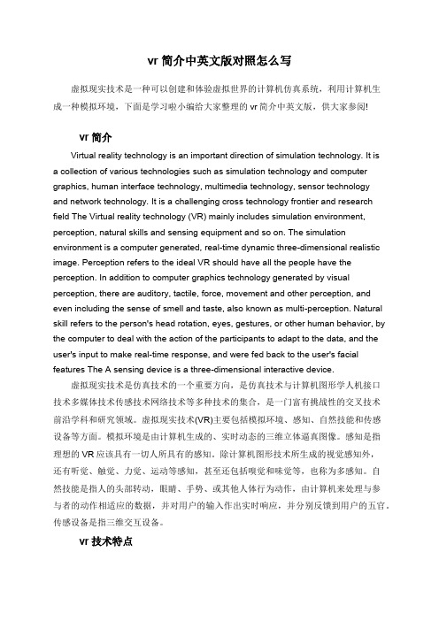
vr简介中英文版对照怎么写虚拟现实技术是一种可以创建和体验虚拟世界的计算机仿真系统,利用计算机生成一种模拟环境,下面是学习啦小编给大家整理的vr简介中英文版,供大家参阅!vr简介Virtual reality technology is an important direction of simulation technology. It isa collection of various technologies such as simulation technology and computer graphics, human interface technology, multimedia technology, sensor technologyand network technology. It is a challenging cross technology frontier and research field The Virtual reality technology (VR) mainly includes simulation environment, perception, natural skills and sensing equipment and so on. The simulation environment is a computer generated, real-time dynamic three-dimensional realistic image. Perception refers to the ideal VR should have all the people have the perception. In addition to computer graphics technology generated by visual perception, there are auditory, tactile, force, movement and other perception, and even including the sense of smell and taste, also known as multi-perception. Natural skill refers to the person's head rotation, eyes, gestures, or other human behavior, by the computer to deal with the action of the participants to adapt to the data, and the user's input to make real-time response, and were fed back to the user's facial features The A sensing device is a three-dimensional interactive device.虚拟现实技术是仿真技术的一个重要方向,是仿真技术与计算机图形学人机接口技术多媒体技术传感技术网络技术等多种技术的集合,是一门富有挑战性的交叉技术前沿学科和研究领域。
虚拟现实与设施管理外文翻译中英文2018

虚拟现实与设施管理中英文2018英文Virtual reality as integration environments for facilities management AbstractPurpose –The purpose of this paper is to explore the use of virtual reality environments (VRE) for maintenance activities by augmenting a virtual facility representation and integrating relevant information regarding the status of systems and the space itself, while providing simple ways to control them.Design/methodology/approach – The research focuses in the implementation of a VRE prototype of a building management system using game engine technologies. To evaluate the prototype, a usability study has been conducted that contrasts the virtual reality interface with a corresponding legacy application showing the users perception in terms of productivity improvement of facilities management (FM) tasks.Findings – The usability tests conducted indicated that VREs have the potential to increase the productivity in maintenance tasks. Users without training demonstrated a high degree of engagement and performance operating a VRE interface, when compared with that of a legacy application. The potential drop in user time and increase in engagement with a VRE will eventually translate into lower cost and to an increase in quality.Originality/value – To date no commonly accepted data model has been proposed to serve as the integrated data model to support facility operation. Although BIM models have gained increased acceptance in architecture engineering and construction activities they are not fully adequate to support data exchange in the post-handover (operation) phase. The presented research developed and tested a prototype able to handle and integrate data in a flexible and dynamic way, which is essential in management activities underlying FM.Keywords Information systems, Simulation, Integration, Decision support systems, Information and communication technology (ICT) application IntroductionFacilities management (FM) aims at creating and maintaining an effective builtenvironment in order to support the successful business operation of an organization (Cotts et al., 2010). The complexity and professionalism underlying modern FM compels practitioners to adopt distinct computerized tools, helpful in automating routine tasks, managing information, monitoring th e building’s performance and assisting in decision-making processes (Abel and Lennerts). Currently, it is amply recognized that Information technology (IT) plays a critical role in the efficiency, both managerial and operational, of FM (Madritsch et al.2008; Elmualim and Pelumi-Johnson, 2009; Lewis and Riley, 2010; Svensson, 1998; Love et al., 2014; Wetzel and Thabet, 2015).In its essence, FM is a multidisciplinary subject that requires the collaboration of actors with expertise from different fields (Cotts et al., 2010; Lewis and Riley, 2010). Within their specific areas of responsibility, they have to interact with distinct IT tools. Managerial roles are likely to interact with computer-aided facility management systems (CAFM) and computerized maintenance management systems (CMMS), employed to manage the characteristics of space and equipment while operational roles are more likely to interact with building managements systems (BMSs) and energy management systems (EMS) used to manage live, i.e., real-time information regarding the space and equipment (Lewis and Riley, 2010). Issues in FM also have to be analyzed from different perspectives. Therefore, this arrangement requires that information from different tools to be brought together to enable a systematic and thorough analysis through data visualization and dashboard (Chong et al., 2014). It has been observed that the costs inherent to lack of communication and data integration for existing buildings portfolio (for information verification costs, delay, and operation and maintenance staff productivity loss) are very significant for an organization (Shi et al., 2016). A better support of IT for integrating information translates to faster effective and just-in-time FM (Svensson, 1998).The subject of integration in IT for FM is not new (IAI, 1996; Howard and Björk, 2008) and has been historically difficult (IAI, 1996; Elmualim and Pelumi-Johnson, 2008). Research and industry practice have developed standards for information exchange to address the interoperability of IT tools in FM (IAI, 1996) and suggestedmaintaining integrated databases of facility-related information (Yu et al., 2000), thus creating a framework where different IT tools become components of the same information system –a facilities management information system (FMIS) (Dennis, 2003; Mozaffari et al., 2005). Moreover, it has been acknowledged that data required to perform certain actions is not up to date and it is delivered in different formats (Migilinskas et al., 2013; Nicał and Wodyński, 2016).More recently, advanced interfaces such as virtual reality environments (VREs) are emerging as a sophisticated and effective ways of rendering spatial information. Such has been the case of the tools used in architecture, engineering and construction (AEC) (Campbell, 2007), and in other specific activities like manufacturing planning (Doil et al., 2003) and industrial maintenance (Sampaio et al., 2009; Fumarola and Poelman, 2011; Siltanen et al., 2007). However, user interfaces of IT tools for FM are not yet taking advantage of the recent advances in VRE. As we will discuss, the typical user interface of CAFM, CMMS and BMS lacks the spatial dynamism and natural interaction offered by a VRE, with noticeable impacts on user productivity.In this paper we argue that VREs, due to their characteristics, could improve both the visualization and interaction with integrated information within an FMIS and, therefore, beneficial for performing FM tasks. To validate this argument, we developed a prototype implementation of a VRE for assisting maintenance activities in the building automation and energy domains. The FM3D prototype augments a virtual facility with information regarding the space characteristics as well as the location, status and energy consumption of equipment, while providing simple ways to control them. Unlike previous applications of VR to FM that rely on CAD (Coomans and Timmermans, 1997) or VRML (Sampaio et al., 2009; Fu et al., 2006) for scene generation, we take advantage of recent game engine technologies for fast and real-time rendering of feature rich representations of the facility, along with space information, equipment conditions and statuses of devices. A user evaluation study was conducted to determine the adequacy of a VRE approach to visualize and interact with integrated FM information toward a responsive intervention. This study compares a VRE interface applied to a building management system with acorresponding legacy application.The remainder of our text is organized as follows. In Section 2 discusses the advanced visualization for FM data integration challenges and emphasizes the opportunities for VREs and new IT tools for FM. In Section 3 describes the research methodology. In Sections 4 and 5 we describe prototype development and evaluation procedures. Section 6 presents the results of the paper. Finally, Section 7 presents the conclusions.Advanced visualization for FM data integrationIntegrated rendering of spatial information is crucial to perceive complex aspects that arise from combining data from multiple sources, and for creating new insights. For example, combining cost data with occupancy information and energy consumption. In FM, integrating information is crucial to create a more complete and faithful model of reality toward an accurate diagnosis and effective response. Integration of spatial information should not be left the ability of the users to integrate mentally different models so that decisions are not hindered by the users inability. However, integrated visualization is quite limited in FM. As mentioned before, integration between tools is limited and the few that support it do not offer effective means to manage overlaying of information. Presently, tools from different vendors display information using different visual elements and layouts causing users acquainted with one tool to find it difficult to interpret data on another.The problem of creating an advanced data visualization solution for FM data integration is twofold. It is necessary first to correctly integrate data from multiple sources into a unified model and second to create and generate an environment that envisages 3D data visualization and real-time interaction with the built environment.Limitations of data integration in FMFM requires integrating large quantities of data. It has been argued that CAFM systems greatly benefit from integrating data of CMMS, BMS and EMS systems both at a data level and at a graphical level (May and Williams, 2012). Yet, despite a few localized integration possibilities (Malinowsky and Kastner, 2010), the current BMS and EMS do not adequately integrate data regarding space characteristics. Notably,some tools support space layout concepts of floor and room in 2D static plans (Lowry, 2002), or even details regarding equipment, but these data live isolated on each tool’s database without any relationship (i.e. integration) with the CAFM system. Such connection is important to explore further characteristics of the space such as, for example, which areas are technical areas or circulation areas. On the other hand, CAFM systems would greatly benefit from real-time information regarding energy utilization, status of environment variables and equipment status enabling understanding how space and equipment is being used.To date no commonly accepted data model has been proposed that is comprehensively enough to serve as the integrated data model to support facility operation. Indeed, it has been noted that interoperability among tools from different vendors is still very ad hoc (Yu et al., 2000). Although BIM models have gained increased acceptance in AEC they are not adequate to support data exchange in the post-handover (operation) phase. For example, BIM models offer no provision to handle trend data, which is essential in management activities underlying FM. Moreover, BIM standards do not handle well data models used by BMS and EMS tools (Yu et al., 2000; Gursel et al., 2007). Another aspect is that querying data for these models is often quite complex for the average user given the large number of entities that must be taken into account (Weise et al., 2009). Therefore querying must be mapped into seamless graphics operations to be performed using different metaphors (e.g. for aggregation, filtering and ranking operations).Advanced facility management interfacesThe idea of extending the functionality of a standard management tool capable of handling facility management and building control networks, is essential in practice and can be achieved by integrating CAFM systems with BMS to obtain a unified control software utility (Malinowsky and Kastner, 2010; Himanen, 2003). This integration grants the ability to automatically monitor and visualize all building areas by illumination, occupation or other spatially located variables and manage them accordingly. For instance one could visualize electrical power consumption of the different building areas and improve efficiency consequentially reducing power costs.Also from an interaction perspective such software should also be complemented with CAD representations. In fact, CAFM systems that were integrated with CAD have been proven most effective (Elmualim and Pelumi-Johnson, 2009). Autodesk has recently announced the Dasher project that aims at using 3D to explore energy data (Autodesk, 2013). The project proposes to be based on Revit BIM to integrate energy data. Energy data must be stored somewhere else. It must be a proprietary BIM model.3D interfaces for facility managementActivities such as inspecting the space for the location of an asset, inspecting the status of equipment or analyzing the energy consumption profile of the space along with its cost and occupancy information are examples of queries that have an underlying spatial dimension. Overall, most IT tools for FM have to manage spatial information, which can be visualized more effectively when rendered in a graphical representation (Karan and Irizarry, 2014; Zhou et al., 2015). Graphical rendering accomplishes instantaneous identification of the space reality along with the relationships of the elements therein to encourage a fast response. Historically, planimetric CAD drawings and geographical information systems (GIS) have been used as an effective way to display and manage spatial information related to facilities (Schürle and Boy, 1998; Rich and Davis, 2010).GIS systems are especially effective at presenting visual representation of spatial data, aiming at a more efficient analysis (Rivest et al., 2005). In building control, a GIS application can be used to better manage a building by improving information access and providing clearness of planning to the decision-making process (Alesheikh et al., 2002). There are some well-known cases of successful GIS implementations in large facilities, such as university campuses[1]. One advantage of a GIS with 3D modeling for building control is enabling 3D information query, spatial analysis, dynamic interaction and spatial management of a building (Keke and Xiaojun).Problem definitionThe Problem definition stage encompasses a literature review and theexploratory study toward the definition of the problem to be solved and the scenarios to be tested. Since dealing with the full complexity of FM is infeasible in practice, this stage was particularly relevant to support the definition of a conceptual model of the prototype tool to develop to validate our hypothesis.Prototype developmentIn the Prototype development stage attention must be given to the data integration architecture, the user interface and the interaction layer, which are implemented using a modular approach that allows easy adaptation to different technologies has been developed. The approach, depicted in Figure 1, uses a web-based interface, thus providing access to FM information in a multitude of platforms, from mobile devices to desktop computers. Since interaction can be performed online, visualization and interaction can be achieved using different platforms. This interface is supplied through a 3D visualization engine developed in Unity 3D that relies on data visualization and integration micro-services supplied by the FM3D application components.EvaluationThe Evaluation stage compares existing legacy system with the VRE approach embodied in the prototype. The evaluation process consists of a comparative study that contrasts the 3D interface applied to the centralized control of a building automation system with a corresponding legacy application. The main goal of the evaluation is to investigate the reliability and possible benefits of 3D virtual environments for automated building by performing a quantitative as well as a qualitative analysis on both systems through user interaction test sessions.In this sense, several tests are run, with distinct types of participants comparing the prototype and an existing legacy application for centralized control and monitoring is executed, featuring a traditional 2D window-icon-menu-pointer interface. To this aim, a legacy application interface depicted in Figure 3 is used, which is already installed and working at the test pilot building. The comparison proceeded along two testing stages, the early prototype stage and the final prototype stage. With the early prototype stage we intended to get a first perspective of howusers would react to our 3D interface. At this time, all main functionalities were already implemented and, therefore, the feedback gathered from this phase did not only contribute to infer possible adjustments to our final prototype, but also provided good preliminary qua ntitative and qualitative results of the prototype’s main functionalities. Both stages of evaluation are structured by the following steps: a pre-test questionnaire to establish user profile; a briefing about test purposes and task description, preceded by a short training session where users freely explored each application for three minutes; and a post-test questionnaire after completing a set of pre-determined tasks in each application. This structure is meant to ensure an even test distribution of the applications. It should be mentioned that in the second phase two more tasks were included to be tested only with the FM3D prototype. These new tasks intend to evaluate functionalities not currently available on the legacy application.During task execution we measure the time that each user takes to complete each task on each application. If a task is not completed after three minutes, the task is considered incomplete. From these data we are able to perform a quantitative comparison between the two applications. The post-test questionnaire, contains direct questions related to the user experience, with special emphasis on the difficulties users faced during task execution to enable a qualitative analysis.User interfaceWhile the lower layers are generally important, in this paper, our main concern is the system’s user interface (Figure 4). Therefore, we will focus our attention on the upper layer of the architecture. As a consequence of using a VRE over a web browser, our solution offers a powerful, yet easy, way to supervise and control small, medium and large facilities. The user interface was developed in Unity 3D Game Engine that enables users to interact with a VRE from within an internet browser.Using simple controls the user can explore the building, inspecting and commanding several devices. To assist the user in navigating through the 3D model, our interface offer two distinct views of the building simultaneously: the main view and the mini-map view. The main view is where most interaction will occur. Thisview allows the user to navigate in the building, from a global viewpoint to detailed local exploration. The navigation in the scene is controlled by the navigation widget, located in the rightmost part of the view. This widget offers rotate, pan and zoom functionalities. The left hand side of the main view presents the control area, which consists on a set of controls offering important functionalities for filtering. Through these controls, the user is able to select which type of device and sensors should be shown or hidden in the visualization, as well as enable or disable navigation aids, such as the orientation guidelines. Additionally, through a text box the user is able to search for a given room, just by typing its name.The mini-map consists of a small view of the complete building, located at the bottom left corner of the screen. It allows users to have a complete view of the building and perceive which part is displayed in the main view. Most important, it offers additional navigation control. Dragging the mouse over the mini-map rotates the miniature view of the building around the vertical axis. If the user chooses to lock this with the main view, changes in any of them will reflect on both. The mini-map view offers also a fast and easy way to change the active floor.Interaction detailsTo minimize the visual complexity, only one floor at a time is rendered in the main view, the so-called active floor. The user selects which floor should be activated through the mini-map or from a specific control in the navigation widget. The selected floor is initially rendered on the main view only with the walls and no devices or sensors shown. The user can then select which categories of sensors and devices should be displayed. In the current version of our prototype the available categories are the lightning, HV AC, temperature and doors.Using the navigation widget, the user can navigate to the desired space in the building to inspect it. When the view gets closer to a room, additional information is depicted, ensuring that the user will not be overloaded with unnecessary information. When possible, the information is shown pictorially, such as the HV AC information represented as gas clouds whose color, size and speed convey information regarding the current status of the device, as illustrated in Figure 5. When the user clicks on adevice a pop-up appears to show additional information and allow the user to control the device.The content of the pop-up window that appears when the user clicks on a device depends on category of the device itself. Obviously, information and controls associated with a HV AC device are distinct than those associated with a lightning system. Figure 6 shows the information window for a light. In this case, besides the on/off state of the light, which can be changed by clicking the corresponding button, additional information is shown. At a glance the user will grasp relevant information such as the lamp type, its power, the number of starts, the total operating hours and its estimated lifetime. If necessary, the user can mark the lamp for replacement or consult informative notes associated with the lamp.The FM3D interface was designed to be easy to use while offering a complete set of functionalities, thus allowing even inexperienced users to operate it to perform maintenance activities. To verify this assumption we organized a formal evaluation of the FM3D system, involving real users.DiscussionRegarding building operators’ perception of the FM3D prototype, results show that users found that a 3D representation of the built environment facilitates both navigation and relating information with the location to which it is pertained. Although this is an encouraging result, it should be taken into account the familiarity of the participants with the built environment. 3D representations of very large built environments may not have these advantages. In this case, it might be necessary to take into account other design considerations to assist users in clearly identifying areas/spaces. An example of a design consideration is overlapping the 3D representation with a photo-realistic (following the same analogy of the well-known Google maps street view perspective).In terms of easiness of use, although users find the FM3D easier to use than the legacy application, they have some difficulties locating some of the information. Specifically, because information is shown according to the aggregation level, it was not always easy to understand where to find a particular piece of information. Thiscan be an obstacle when considering buildings that have many layers and/or integrated spaces that require users to perform a high number of zoom in and out to access the information. Regarding the learnability component, users found the FM3D interface was easier to learn regarding navigation, command and information retrieval functionality – this is highlighted further by the quantitative results, especially those of the advanced participant. In terms of satisfaction it was observed that participants found the FM3D prototype superior both in usefulness and its ability to improve task performance comparing to the legacy application.Through the usability tests that we have conducted we have reasons to believe that 3D interactive environments have the potential to significantly increase the productivity in maintenance tasks. In these tests, users without training demonstrated a high degree of engagement and performance operating our 3D interface prototype, especially when compared with the legacy application. The potential decrease in user time and increase in engagement with a 3D environment could eventually translate into lower cost and increase in quality, potentially turning 3D-based interface the option of choice in future IT tools for BMS.ConclusionsFM activities are increasingly supported by IT tools and their effective usage ultimately determines the performance of the FM practitioner. In this paper, we argued the usability of IT tools for FM suffers from a number of limitations mostly related to the lack of a true integration at the interface level and an inadequate handling of spatial information. Moreover, their steep learning curve makes them unsuited for inexperienced or non-technical users. We then propose VREs as a solution for the problem and validate our hypothesis by implementing FM3D, a prototype VRE for monitoring and control of buildings and centered around the requirements of FM activities with respect to integration, visualization and interaction with spatial information.This work validates literature reports pointing to an increase in performance of VREs over traditional interfaces and shows that new approaches to interact with spatial information not only feasible but also desirable. The usability tests we haveconducted indicate that VREs have the potential to greatly increase the productivity in maintenance tasks. Users without training demonstrated a high degree of engagement and performance while operating a VRE interface, when compared with that of a legacy application. The potential drop in user time and increase in engagement with a VRE will eventually translate into lower cost and to an increase in quality, potentially turning VRE-based interface the option of choice in future IT tools for FM. The major contribution of this paper was to demonstrate that VREs have low barrier to entry and have the potential to replace existing legacy BMS user interfaces. Additionally, it showed that all users regard VREs as a natural next step with respect to the interaction with FM systems.In our approach it remains unclear to what extent the integration at the interface level is contributing to increase the user productivity. Presumably, not all maintenance activities benefit, in the same way, from an approach such as the one we propose. Therefore, as future developments, additional studies should aim at gaining insight on which aspects of a VRE interface contribute to which other maintenance activities considering different interfaces (web-based interfaces and from mobile devices). These studies should begin by mapping the information needs for each activity and, thereafter, assessing existing FM tool interfaces and the VRE prototype against them. Moreover, since the evaluation is based on a narrow mix of FM tasks, further studies are required to establish the causal relationship between the employment of VREs in FM and increases in productivity, especially those involving multiple tools.中文虚拟现实作为设施管理的集成环境摘要研究目的–本研究目的是通过增加虚拟设施整合有关系统状态和空间本身的相关信息,同时提供控制它们的简单方法,探索将虚拟现实环境(VRE)用于设备维护活动。
外文文献翻译-设计一个沉浸式的虚拟现实界面布局规划
设计一个沉浸式的虚拟现实界面布局规划摘要这篇论文论述了生产布局规划被认为是虚拟现实运用的一个合适全新领域的原因;开发了一个用于虚拟布局规划工具的框架和做一份使用沉浸式虚拟现实系统来检测布局设计问题的研究报告,汇报了对比沉浸式虚拟现实系统与基于监控式式系统,以此来检测布局设计局限的研究。
所提议的框架评估已经被引用在一项研究上,这份研究还没有对于一个交互式的变更的空间布局的规范。
研究的主要目的是比较一个沉浸式系统和一个基于监控式虚拟现实系统在工厂布局分析上的应用。
研究组成员调查了车间的环境,其中包括三个主要的车间布局的问题(设备布置,空间利用率?,和设备位置),给出了可行性改进的评估,2000艾斯维尔科技B.V版权所有。
关键字:虚拟现实,NMD,布局设计,制造单元1.介绍虚拟现实(VR),不像其他的新技术,从来没有被大肆宣传。
自从BBC在1993年1月19号的9点当新闻里面简短得表达了VR,其中包括了一台适用HMD的VR 型喷气式发动机,这项技术便引起了巨大的热潮和关注。
目前,然而情况有些化变,虚拟现实的行话不再难以理解。
虚拟现实已经变成一个负面的项目,承诺了太多缺却都没有做到。
部分原因是夸张的期望,以及何处可以运用虚拟现实来实现显著定量的好处的调研,可以计量的好处的深入调查。
目前,虚拟现实的研究主要针对质量的应用。
目前,VR的研究用于寻找质量工程应用,这能体现优越的视觉效果和互动能力,远超于这一技术的缺点。
2.背景车间布局在制造环境中不是一个新的话题。
布局脚本的选择是基于传统用户定义的特征,比如漫游频率,漫游距离,和零件、设备、操作者的物理属性【1】。
正如研究显示,第一阶段的规划、总体规划设计,也就是所谓的模块化布局【2】。
然而,当设备的准确位置和方位在详细的布局中被设定时,这些数据缺乏实用性。
目前工厂设备的方式,比如,制造单元的形成,已经暴露了问题,这就要求一种新的设计工具【3,4】。
制造单元的目的是把流水线(典型的有汽车转配线)的效率和功能布局(车床部件,磨床部件,转配部件等等)的柔性通过单元或模块结合起来。
虚拟现实与医疗教学外文翻译中英文2019
沉浸式虚拟现实与医疗教学中英文2019英文Medical Student Perspectives on the Use of Immersive Virtual Reality forClinical Assessment TrainingMatthew Zackoff, Francis Real,Bradley Cruse,David Davis,Melissa KleinWhat's New?Medical students reported an immersive virtual reality (VR) curriculum on respiratory distress as clinically accurate and likely to impact future patient assessment. VR training was rated as equally or more effective than high-fidelity mannequins and standardized patients but less effective than bedside teaching.Keywords:Clinical assessment,respiratory distress,virtual reality BackgroundThe practice of medicine has traditionally relied on an apprenticeship model for clinical training – an approach in which bedside teaching was the primary source for knowledge transfer. However, the frequency of bedside teaching is declining due to duty hour restrictions, increased patient turnover, and competing demands for physicians' time.Alternatives to bedside teaching have emerged including simulation-based medical education though current approaches arelimited in applicability to and functionality for pediatric training. For instance, standardized patients are not available for many pediatric conditions especially for diseases that predominantly affect infants. Moreover, patient simulators often cannot display critical physical exam findings for discriminating between sick and healthy patients (eg mental status, work of breathing, perfusion changes).An emerging educational modality, immersive virtual reality (VR), could potentially fill this gap. Immersive VR utilizes a three-dimensional, computer generated environment in which users interact with graphical characters (avatars). While screen-based simulation training has been demonstrated to enhance learning outcomes, immersive VR has the potential to have a broader impact through increased learner engagement, and improved spatial representation and learning contextualization. To date, this technology has demonstrated effectiveness in communication skills training; however, it has not been investigated for clinical assessment training. To evaluate the role of immersive VR in medical student clinical assessment training, we created a VR curriculum focused on respiratory distress in infants. Our pilot study explored medical student attitudes toward VR and perceptions of VR compared to other common medical educational methods.Educational Approach and InnovationSetting and Study PopulationAn IRB approved prospective pilot study was conducted at Cincinnati Children's Hospital Medical Center, a large academic children's hospital, during the 2017 to 2018 academic year. A randomized sample of third-year medical students, based upon predetermined clinical team assignment during their pediatric rotation, was invited to participate in a VR curriculum.Curriculum DesignThe curricular goal, to improve third year medical students' ability to appropriately categorize a pediatric patient's respiratory status, aligns with an Association of American Medical Colleges Core Entrustable Professional Activity for entering residency, the ability to recognize a patient that requires an urgent or emergent escalation of care.To address this goal, an immersive VR curriculum using the clinical scenario of an admitted infant with bronchiolitis was developed collaboratively between clinicians, educators, and simulation developers.A virtual Cincinnati Children's Hospital Medical Center inpatient hospital room was created using the Unity development platform and was experienced through an Oculus Rift headset. The environment included a vital signs monitor, virtual stethoscope, and avatars for the patient and preceptor. The patient avatar could demonstrate key exam findings (ie mental status, work of breathing, and breath sounds) that correlated with three clinical scenarios: 1) no distress, 2) respiratory distress, and 3)impending respiratory failure. The displayed vital signs and auscultatory findings matched the clinical status of the patient. Learners received feedback on their performance immediately following each simulated case. The preceptor avatar, controlled by a physician facilitator (M.Z., F.R.), guided the student through the VR simulation. Learners were expected to recognize and interpret the vital signs, physical exam, and auscultatory findings and come to an overall assessment of the patient's respiratory status. Detailed algorithms correlating learner input to avatar responses allowed for standardization of the avatar preceptor prompts. For example, if a student did not comment on the patient's lung sounds, the facilitator is guided to select the avatar prompt, “What do you think of his lung sounds?” Facilitator-provided feedback for each scenario was standardized to ensure consistent learner experiences.Scenarios were piloted on four critical care attending physicians, two hospitalists, two general pediatricians, four critical care fellows, four senior pediatric residents, and four medical students to assess the accuracy of the findings portrayed in the clinical scenarios as well as the feasibility of the planned facilitation. Iterative changes were made to the VR simulation based upon feedback.Survey Design and ImplementationImmediately following the VR curriculum, students completed a survey to assess immersion within the VR environment using questionsderived from a validated instrument.15 Demographic data and attitudes toward the VR curriculum including its perceived effectiveness compared to other education methods were assessed on a 5-point Likert scale via a survey created de novo with piloting prior to use. Survey results were analyzed with binomial testing.ResultsAll eligible students consented to participate in the research study (n = 78). Ages ranged from 20 to 39 with an equal distribution between male and female. Students self-identified as White (51.3%), Asian (28.2%), Black (7.7%), Hispanic/Latino (3.9%), or other (9.0%). Most students reported a strong sense of presence in the VR environment (85%) and the vast majority noted that the scenarios captured their attention and senses (96% and 91%, respectively).A majority of students agreed or strongly agreed that that the simulations were clinically accurate (97.4%), reinforced key learning objectives (100%), and would impact future care provision (98.7%). In addition, students reported VR training as more effective (P < .001) than reading, didactic teaching, online learning, and low fidelity mannequins. VR training was rated as equally or more effective (P < .001) than high fidelity mannequins and standardized patients. The only modality that VR was rated less effective than was bedside teaching.Figure. Binomial testing demonstrates that a statistical majority of students found virtual reality training more effective than reading, didactic teaching, online learning, and low fidelity mannequins, and equally or more effective than high fidelity mannequins and standardized patients.Discussion and Next StepsThis study represents a novel application of immersive VR for medical student training. The majority of student participants reported a sense of presence within the VR environment and identified the modality as equal or superior in perceived effectiveness to other training options such as standardized patients and high-fidelity mannequin simulations while rated less effective than bedside teaching. These findings are consistent with the findings of Real et al13 that learners perceived VR as equally effective to standardized patients for communication training. Our learners expressed similar perceptions regarding the use of VR forclinical assessment training –expanding the potential applications forVR-based education.The assessment of a patient's respiratory status, and importantly the recognition of need for emergent escalation of care is a core clinical competency that directly relates to patient safety. The ability of immersive VR to convey specific critical exam findings could aid in accelerating junior learners' competence related to identification of impending respiratory failure and potentially impact future care provision. The learnings from this pilot could be applied to other clinical scenarios (eg sepsis) given immersive VR's ability to accurately simulate key exam findings.This study has several limitations. First, it was conducted at a single site with only third year medical students. Second, the evaluation focused on students' perceptions toward the effectiveness of VR-based education in general rather than specifically focusing on VR-based education on pediatric respiratory distress. Though we could not standardize students' exposure to the comparison education modalities, all students underwent a high-fidelity simulation focused on respiratory distress as part of their pediatric rotation. This high fidelity simulation occurred prior to the VR curriculum, and thus represented a consistent reference for all of the students who completed the study survey.A final significant consideration for this study is the generalizability of the approach. With each passing year and iteration of availableequipment, the cost of VR compatible headsets and computers continue to fall. We utilized the Oculus Rift headset and a VR capable computer, which together cost on the order of $2000. The development platform, Unity, is an open source platform available at no cost. We are fortunate to have VR developers as employees of our simulation center, facilitating the development of new scenarios, and represent a resource that may currently be unavailable at many other institutions.Next steps include establishing response process validity through assessment of learner application of knowledge gained during the VR curriculum. Additional research goals include exploring the effectiveness of immersive VR at additional sites to assess generalizability, directly comparing VR head-to-head with other educational modalities (eg standardized patients, high-fidelity simulations), and evaluating change in actual clinical practice as well as the costs associated with these modalities to explore the feasibility of broader implementation of VR training. The findings from this pilot study suggest that immersive VR may be an effective supplement to bedside teaching due to its ability to accurately represent real-life environments and clinical scenarios in a standardized format that is safe for learners and patients.中文使用沉浸式虚拟现实进行医学临床培训的研究什么是新的?医学院的学生报告说,关于呼吸窘迫的沉浸式虚拟现实(VR)课程在临床上是准确且有效的,并且可能会影响未来的患者救治效果。
虚拟现实(VR)
概述“虚拟现实”是来自英文“Virtual Reality”,简称VR技术。
最早由美国的乔·拉尼尔在20世纪80年代初提出。
虚拟现实技术(Ⅵ)是集计算机技术、传感器技术、人类心理学及生理学于一体的综合技术,其是通过利用计算机仿真系统模拟外界环境,主要模对象有环境、技能、传感设备和感知等,为用户提供多信息、三维动态、交互式的仿真体验。
特点虚拟现实主要有3个特点:沉浸感(Immersive)、交互性(Interactive)、想象性(Imagination)。
沉浸感是指计算机仿真系统模拟的外界环境十分逼真,用户完全投入三维虚拟环境中,对模拟环境难分真假,虚拟环境里面的一切看起来像真的,听起来像真的,甚至闻起来等都像真的,与现实世界感觉一模一样令人沉浸其中。
交互性是指用户可对虚拟世界物体进行操作并得到反馈,如用户可在虚拟世界中用手去抓某物体,眼睛可以感知到物体的形状,手可以感知到物体的重量,物体也能随手的操控而移动。
想象性是指虚拟世界极大地拓宽了人在现实世界的想象力,不仅可想象现实世界真实存在的情景也可以构想客观世界不存在或不可发生的情形。
根据用户沉浸程度和参与方式的不同,虚拟现实可分为4类:非沉浸式虚拟现实、沉浸式虚拟现实、分布虚拟现实系统及增强虚拟现实系统。
应用一、幼儿园教学应用综合应用(1)逼真式的体验教学。
VR虚拟现实技术最大的优势在于开放自由的教学空间,解决了课堂互动,答疑解惑,动手实操等问题。
例如:运用VR职业模拟体验,可以让幼儿体验美食大厨、上班族和便利店店员,幼儿们不仅需要像在真实生活中那样完成工作内容,更重要的是作为一种职业冒险类模拟体验游戏,幼儿们将会在游戏过程中体验到更多置身未来难以适应的困惑感,幼儿们就可以在游戏过程中获得很多人生感悟。
同时,将头盔式VR 装备应用于幼儿课程教学中,教师课前将教程编排好,应用情景式教学内容设置给将给幼儿带来沉浸式的教学体验,学习就像看电影,从一定程度上增加了学习的乐趣,补充了教学素材。
毕业论文外文翻译--虚拟现实技术的发展过程及研究现状(适用于毕业论文外文翻译+中英文对照)
虚拟现实技术的发展过程及研究现状虚拟现实技术是近年来发展最快的技术之一,它与多媒体技术、网络技术并称为三大前景最好的计算机技术。
与其他高新技术一样,客观需求是虚拟现实技术发展的动力。
近年来,在仿真建模、计算机设计、可视化计算、遥控机器人等领域,提出了一个共同的需求,即建立一个比现有计算机系统更为直观的输入输出系统,成为能与各种船感器相联、更为友好的人机界面、人能沉浸其中、超越其上、进出自如、交互作用的多维化信息环境。
VR技术是人工智能、计算机图形学、人机接口技术、多媒体技术、网络技术、并行计算技术等多种技术的集成。
它是一种有效的模拟人在自然环境中视听、动等行为的高级人机交互技术。
虚拟现实(Virtual Reality ):是一种最有效的模拟人在自然环境中视、听、动等行为的高级人机交互技术,是综合计算机图形技术、多媒体技术、并行实时计算技术、人工智能、仿真技术等多种学科而发展起来的20世纪90年代计算机领域的最新技术。
VR以模拟方式为使用者创造一个实时反映实体对象变化与相互作用的三维图像世界,在视、听、触、嗅等感知行为的逼真体验中,使参与者可直接探索虚拟对象在所处环境中的作用和变化;仿佛置身于虚拟的现实世界中,产生沉浸感(immersive)、想象(imaginative和实现交互性interactive) 。
VR技术的每一步都是围绕这三个特征而前进的。
这三个特征为沉浸特征、交互特征和构想特征。
这三个重要特征用以区别相邻近的技术,如多媒体技术、计算机可视化技术沉浸特征,即在VR提供的虚拟世界中,使用户能感觉到是真实的进入了一个客观世界;交互特征,要求用户能用人类熟悉的方式对虚拟环境中的实体进行观察和操纵;构想特征:即“从定性和定量综合集成环境中得到感性和理性的认识:从而化概念和萌发新意”。
1.VR技术发展的三个阶段VR技术的发展大致可分为三个阶段:20世纪50年代至70年代VR技术的准备阶段;80年代初80年代中期,是VR 技术系统化、开始走出实验室进入实际应用的阶段;80年代末至90年代初,是VR技术迅猛发展的阶段。
- 1、下载文档前请自行甄别文档内容的完整性,平台不提供额外的编辑、内容补充、找答案等附加服务。
- 2、"仅部分预览"的文档,不可在线预览部分如存在完整性等问题,可反馈申请退款(可完整预览的文档不适用该条件!)。
- 3、如文档侵犯您的权益,请联系客服反馈,我们会尽快为您处理(人工客服工作时间:9:00-18:30)。
外文翻译设计题目:基于虚拟现实的虚拟实验室的研究原文1:VRML译文1:虚拟现实原文2:VR-LAB译文2:虚拟现实实验室原文1:VRMLDurch die immer bessere Hardware ist es heute nicht mehr nötig,für anspruchsvolle 3D-Grafiken spezielle Grafik-Workstations zu verwenden.Auf modernen PCs kann jeder durch dreidimensionale Welten fliegen.Um solche Welten zu definieren und sie über das Internet zu verbinden,wurde die Sprache VRML entwickelt. In diesem Beitrag geben wir einen Überblick über die grundlegenden Konzepte der Version 2.0 von VRML.●Geschichte von VRMLIm Frühling 1994 diskutierte auf der ersten -Konferenz in Genf eine Arbeitsgruppe über Virtual Reality-Schnittstellen für das .Es stellte sich heraus, daßman eine standardisierte Sprache zur Beschreibung von 3D-Szenen mit Hyperlinks brauchte. Diese Sprache erhielt in Anlehnung an HTML zuerst den Namen Virtual Reality Markup Language.Später wurde sie in Virtual Reality Modeling Language umbenannt. Die VRML-Gemeinde spricht die Abkürzung gerne …Wörml“ aus. Basierend auf der Sprache Open Inventor von Silicon Graphics (SGI) wurde unter der Federführung von Mark Pesce die Version 1.0 von VRML entworfen. Im Laufe des Jahres 1995 entstanden eine Vielzahl von VRML Browsern (u. a.WebSpace von SGI) und Netscape bot schon sehr früh eine hervorragende Erweiterung, ein sogenanntes PlugIn, für seinen Navigator an.Die virtuellen Welten, die man mit VRML 1.0 spezifizieren kann,sind zu statisch.Zwar kann man sich mit einem guten VRML-Browser flott und komfortabel durch diese Welten bewegen,aber die Interaktion ist auf das Anklicken von Hyperlinks beschränkt. Im August ’96,anderthalb Jahre nach der Einführung von VRML 1.0,wurde auf der SIGGraph ’96 die Version VRML 2.0 vorgestellt.Sie basiert auf der Sprache Moving Worlds von Silicon Graphics. Sie ermöglicht Animationen und sich selbständig bewegende Objekte.Dazu mußte die Sprache um Konzepte wie Zeit und Events erweitert werden.Außerdem ist es möglich, Programme sowohl in einer neuen Sprache namens VRMLScript oder in den Sprachen JavaScript oder Java einzubinden.●Was ist VRML?Die Entwickler der Sprache VRML sprechen gerne von virtueller Realität und virtuellen Welten.Diese Begriffe scheinen mir aber zu hoch gegriffen für das, was heute technisch machbar ist: eine grafische Simulation dreidimensionaler Räume und Objekte mit eingeschränktenInteraktionsmöglichkeiten.Die Idee von VRML besteht darin, solche Räume über das zu verbinden und mehreren Benutzern gleichzeitig zu erlauben, in diesen Räumen zu agieren.VRML soll architekturunabhängig und erweiterbar sein. Außerdem soll es auch mit niedrigen Übertragungsraten funktionieren. Dank HTML erscheinen Daten und Dienste des Internets im World Wide Web als ein gigantisches verwobenes Dokument, in dem der Benutzer blättern kann.Mit VRML sollen die Daten und Dienste des Internets als ein riesiger Raum,ein riesiges Universum erscheinen, in dem sich der Benutzer bewegt – als der Cyberspace.●Grundlegende Konzepte von VRML 2.0VRML2.0 ist ein Dateiformat,mit dem man interaktive,dynamische, dreidimensionale Objekte und Szenen speziell fürs World- Wide-Web beschreiben kann.Schauen wir uns nun an,wie die in dieser Definition von VRML erwähnten Eigenschaften in VRML realisiert wurden.●3D ObjekteDreidimensionale Welten bestehen aus dreidimensionalen Objekten die wiederum aus primitiveren Objekten wie Kugeln,Quadern und Kegeln zusammengesetzt wurden.Beim Zusammensetzen von Objekten können diese transformiert,d.h. z.B.vergrößert oder verkleinertwerden.Mathematisch lassen sich solche Transformationen durch Matrizen beschreiben und die Komposition von Transformationen läßt sich dann durch Multiplikation der zugehörigen Matrizen ausdrücken.Dreh-und Angelpunkt einer VRML-Welt ist das Koordinatensystem.Position und Ausdehnung eines Objektes können in einem lokalen Koordinatensystem definiert werden.Das Objekt kann dann in ein anderes Koordinatensystem plaziert werden, indem man die Position, die Ausrichtung und den Maßstab des lokalen Koordinatensystems des Objektes in dem anderen Koordinatensystem festlegt.Dieses Koordinatensystem und die in ihm enthaltenen Objekte können wiederum in ein anderes Koordinatensystem eingebettet werden.Außer dem Plazieren und Transformieren von Objekten im Raum,bietet VRML die Möglichkeit,Eigenschaften dieser Objekte, etwa das Erscheinungsbild ihrer Oberflächen festzulegen.Solche Eigenschaften können Farbe,Glanz und Durchsichtigkeit der Oberfläche oder die Verwendung einer Textur, die z.B.durch eine Grafikdatei gegeben ist, als Oberfläche sein.Es ist sogar möglich MPEG-Animationen als Oberflächen von Körpern zu verwenden,d.h.ein MPEG-Video kann anstatt wie üblich in einem Fenster wie auf einer Kinoleinwand angezeigt zu werden, z.B.auf die Oberfläche einer Kugelprojiziert werden.Abb.1 VRML 2.0 Spezifikation eines Pfeils#VRML V2.0 utf8DEF APP Appearance{marterial Material{ diffuseColor 100}}Shape{appearance USE APP geometry Cylinder{radius 1 height 5}}Anchor{ChildrenTransform{ translation 0 4 0ChildrenShape{ appearance USE APPgeometryCylinder { bottomRadius 2Height 3}}}Url"anotherWorld.wrl"}●VRML undWas VRML von anderen Objektbeschreibungssprachen unterscheidet, ist die Existenz von Hyperlinks, d. h.durch Anklicken von Objekten kann man in andere Welten gelangen oder Dokumente wie HTML-Seiten in den -Browser laden. Es ist auch möglich,Grafikdateien, etwa für Texturen,oder Sounddateien oder andere VRML-Dateien einzubinden, indem man deren URL, d. h. die Adresse der Datei im angibt.●InteraktivitätAußer auf Anklicken von Hyperlinks können VRML-Welten auf eine Reihe weiterer Ereign isse reagieren.Dazu wurden sogenannte Sensoren eingeführt.Sensoren erzeugen Ausgabe-Events a ufgrund externer Ereignisse wie Benutzeraktionen oder nach Ablauf einesZeitintervalls.Events können an andere Objekte geschickt werden,dazu werden die Ausgabe-Event s von Objekten mit den Eingabe-Events anderer Objekte durch sogenannte ROUTES verbunden. Ein Sphere-Sensor zum Beispiel wandelt Bewegungen der Maus in 3D-Rotationswerte um.Ein 3 D-Rotationswert besteht aus drei Zahlenwerten, die die Rotationswinkel in Richtungder drei Koo rdinatenachsen angeben. Ein solcher 3D-Rotationswert kann an ein anderes Objekt geschickt wer den, das daraufhin seine Ausrichtung im Raum entsprechend verändert.Ein anderes Beispiel füreinen Sensor ist der Zeitsensor.Er kann z.B.periodisch einen Event an einen Interpolator schicke n.Ein Interpolator definiert eine abschnittsweise lineare Funktion,d.h. die Funktion ist durch Stüt zstellen gegeben und die dazwischenliegenden Funktionswerte werden linear interpoliert.Der Inter polator erhält also einen Eingabe-Event e vom Zeitsensor,berechnet den Funktionswert f(e) und schickt nun f(e) an einen anderen Knoten weiter.So kann ein Interpolator zum Beispiel die Posi tion eines Objekts im Raum in Abhängigkeit von der Zeit festlegen.Dies ist der grundlegende Mechanismusfür Animationen in VRML.Abb.2 Browserdarstellungen des PfeilsDynamikVorreiter der Kombination von Java und Java Script-Programmen mit VRML-Welten war N etscape’s Live3D,bei dem VRML 1.0 Weltenüber Netscape’s LiveConnect-Schnittstelle von Java -Applets oder JavaScript-Funktionen innerhalb einer HTML-Seite gesteuertwerden können. In VRML 2.0 wurde in die Sprache ein neues Konstrukt, der sogenannteSkriptk noten, aufgenommen.Innerhalb dieses Knotens kann Java und Java Script-Code angegeben werde n,der z.B.Events verarbeitet. Im VRML 2.0 Standard wurdenProgrammierschnittstellen (Application Programming Interface API) festgelegt, die den Zugriff aufVRML-Objekte von Programmierspr achenaus erlauben, nämlich das Java API und das JavaScriptAPI. Das API ermöglicht es, daßP rogramme Routes löschen oder hinzufügen und Objekte und ihre Eigenschaften lessen oder ände rn können.Mit diesen Programmiermöglichkeiten sind der Phantasie nun kaum noch Grenzen ges etzt.●VRML und dann?Eines der ursprünglichen Entwicklungsziele von VRML bleibt auch bei VRML 2.0 ungelöst: Es gibt immer noch keinen Standard für die Interaktion mehrerer Benutzer in einer 3D-Szene.Produkte, die virtue-lle Räume mehreren Benutzern gleichzeitig zugänglich machen,sind al-lerdings schon auf dem Markt (Cybergate von Black Sun,CyberPassage von Sony). Des weiteren fehlt ein Binärformat wie etwa das QuickDra-w 3D-Metafile-Format von Apple,durch das die Menge an Daten reduzie-rt würde, die über das Netz geschickt werden müssen,wenn eine Szene geladen wird.Gerade in Mehrbenutzerwelten spielt der sogenannte Ava-tar eine große Rolle. Eine Avatar ist die virtuelle Darstellung des Benutzers.Er befindet sich am Beobachtungspunkt,von dem aus der Ben-utzer die Szene sieht.Bewegtsich der Benutzer allein durch die Sze-ne,dann dient der Avatar nurdazu,Kollisionen des Benutzers mit Obje-kten der Welt festzustellen.In einer Mehrbenutzerwelt jedoch legt d-er Avatar auch fest,wieein Benutzer von anderen Benutzern gesehen wird.Standards für diese und ähnliche Probleme werden derzeit in Arbe-itsgruppen des Ende 1996 gegründeten VRML-Konsortiums ausgearbeitet.●Literatur1. San Diego Super puting Center: The VRML Repository./vrml/.Enthält Verweise auf Tutorials,Spezifikationen,Tools und Browser im2. Diehl, S.: Java & Co.Addison-Wesley,Bonn, 19973. Hartman, J.;Wernecke, J.: The VRML 2.0 Handbook – BuildingMoving Worlds on the Web.Addison-Wesley, 19964. V AG (VRML Architecture Group): The Virtual Reality ModelingLanguage Specification – Version 2.0, 1996./VRML2.0/FINAL/Eingegangen am 1.09.1997Author :Stephan DiehlNationality :GermanyOriginate from :Informatik-Spektrum 20: 294–295 (1997) © Springer-Verlag 1997译文1:虚拟现实建模语言本文给出了VRML2.0的基本概念●VRML的历史1994年春季第一届万维网在日内瓦举行,会议上就VRML进行了讨论。