单片机-外文翻译-外文文献-英文文献-基于单片机的超声波测距系统的研究与设计
基于单片机超声波测距系统的设计和实现
基于单片机超声波测距系统的设计和实现超声波测距系统是利用超声波传播速度较快的特性,通过发射超声波并接收其回波来测量距离的一种常见的测距方式。
在本文中,我们将介绍基于单片机的超声波测距系统的设计和实现。
一、系统设计原理超声波测距系统主要由超声波发射器、超声波接收器、单片机和显示器组成。
其工作原理如下:1.发送超声波信号:超声波发射器通过单片机控制,向外发射超声波信号。
超声波的发射频率通常在40kHz左右,适合在空气中传播。
2.接收回波信号:超声波接收器接收到回波信号后,将信号经过放大和滤波处理后送入单片机。
3.距离计算:单片机通过测量超声波发射和接收的时间差来计算距离。
以声速343m/s为例,超声波的往返时间与距离之间的关系为:距离=时间差×声速/2、通过单片机上的计时器和计数器来测量时间差。
4.数据显示:单片机将计算得到的距离数据通过显示器显示出来,实时展示被测物体与超声波传感器之间的距离。
二、系统设计步骤1.系统硬件设计:选择合适的超声波模块,其具有超声波发射器和接收器功能,并可通过接口与单片机连接。
设计好电源电路以及超声波传感器与单片机之间的连接方式。
2.系统软件设计:根据单片机的型号和编程语言,编写相应的程序。
包括超声波信号的发射和接收控制,计时和计数功能的编程,距离计算和数据显示的实现。
3.硬件连接和调试:将硬件连接好后,对系统进行调试。
包括超声波模块与单片机的连接是否正确,超声波信号的发射和接收是否正常,计时和计数功能是否准确等。
5.优化和改进:根据实际测试结果,对系统进行优化和改进。
如增加滤波和放大电路以提高信号质量,调整超声波模块的发射频率,改进显示方式等。
三、系统实现效果完成以上设计和实施后,我们可以得到一个基于单片机的超声波测距系统。
该系统使用简单,测距精度高,响应速度快,适用于各种距离测量的应用场景。
同时,该系统还可根据具体需求进行各种改进和扩展,如与其他传感器结合使用,增加报警功能等。
外文文献翻译- 基于单片机的频率计设计本科学位论文
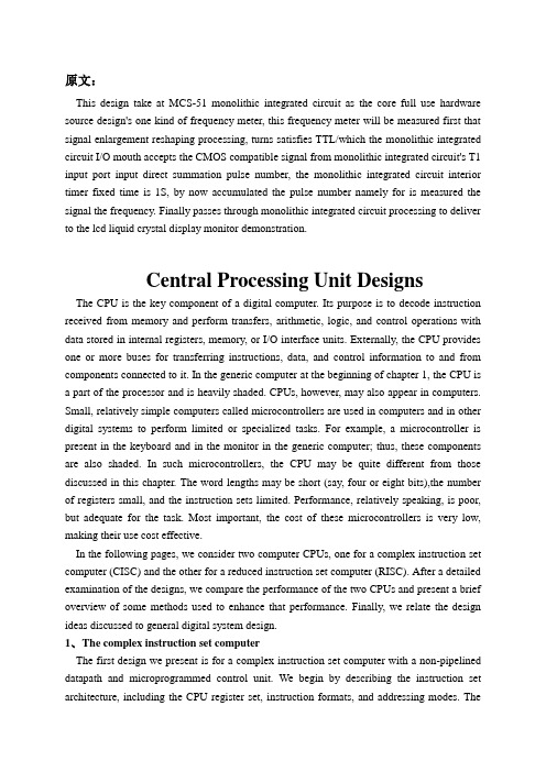
原文:This design take at MCS-51 monolithic integrated circuit as the core full use hardware source design's one kind of frequency meter, this frequency meter will be measured first that signal enlargement reshaping processing, turns satisfies TTL/which the monolithic integrated circuit I/O mouth accepts the CMOS compatible signal from monolithic integrated circuit's T1 input port input direct summation pulse number, the monolithic integrated circuit interior timer fixed time is 1S, by now accumulated the pulse number namely for is measured the signal the frequency. Finally passes through monolithic integrated circuit processing to deliver to the lcd liquid crystal display monitor demonstration.Central Processing Unit DesignsThe CPU is the key component of a digital computer. Its purpose is to decode instruction received from memory and perform transfers, arithmetic, logic, and control operations with data stored in internal registers, memory, or I/O interface units. Externally, the CPU provides one or more buses for transferring instructions, data, and control information to and from components connected to it. In the generic computer at the beginning of chapter 1, the CPU is a part of the processor and is heavily shaded. CPUs, however, may also appear in computers. Small, relatively simple computers called microcontrollers are used in computers and in other digital systems to perform limited or specialized tasks. For example, a microcontroller is present in the keyboard and in the monitor in the generic computer; thus, these components are also shaded. In such microcontrollers, the CPU may be quite different from those discussed in this chapter. The word lengths may be short (say, four or eight bits),the number of registers small, and the instruction sets limited. Performance, relatively speaking, is poor, but adequate for the task. Most important, the cost of these microcontrollers is very low, making their use cost effective.In the following pages, we consider two computer CPUs, one for a complex instruction set computer (CISC) and the other for a reduced instruction set computer (RISC). After a detailed examination of the designs, we compare the performance of the two CPUs and present a brief overview of some methods used to enhance that performance. Finally, we relate the design ideas discussed to general digital system design.1、T he complex instruction set computerThe first design we present is for a complex instruction set computer with a non-pipelined datapath and microprogrammed control unit. We begin by describing the instruction set architecture, including the CPU register set, instruction formats, and addressing modes. TheCISC nature of the instruction set architecture is demonstrated by its memory-to-memory access for data manipulation instructions, eight addressing modes, two instruction format lengths, and instructions that require significant sequences of operations for their execution.We design a datapath for implementing the CISC architecture. The datapath is based on the one initially described in Section 7-9 and incorporated into a CPU in section 8-10. modifications are made to the register file, the function unit, and the buses to support the present instruction set architecture.Once the datapath has been specified, a control unit is designed to complete the implementation of the instruction set architecture. The design of the control unit must involve a coordinated definition of both the hardware organization and the microprogram organization. In particular , dividing the microprogram into microroutines, while at the same time designing the sequencer with which they interact, is a key part of the design. Even the instruction fields and opposed are tied to this coordinated effort. Following the definition of the hardware and microcode organizations, we detail essential parts of the microcode and the microroutines for representative operations.Instruction set architectureFigure 10-1 shows the CISC register set accessible to the programmer. All registers have 16 bits. The register file has eight registers, R0 though R7.R0 is a special register that always supplies the value zero when it is used as a source and discards the result when it is used as a destination.In additional to the register file, there is a program counter PC and stack pointer SP. The presence of a stack pointer indicates that a memory stack is a part of the architecture . the final register is the processor status register PSR, which contains information only in its rightmost the five bits; the remainder of the register is assumed to contain zero. The PSR contains thefour stored status bit values Z,N,C,and V in positions 3 through 0, respectively. In additional, a stored interrupt enable bit EI appears in position 4.Table 10-1 contains the 42 operations performed by the instructions. Each operation has a mnemonic and a carefully selected oppose. The operations are divided into four groups based on the number of explicit operands and whether the operation is branch. In addition, the status bits affected by the operation are listed.Figure 10-2 gives the instruction formats for the CPU. The generic instruction format has five fields. The first, OPCODE, specifies of the operation. The next two, MODE and S , are used to determine the addresses of the operands. The last two fields, SRC and DST, are the 3-bit source register and destination register address fields, respectively. In addition, there is an optional second word W that appears with some instructions as an operand or an address, but not with others.The first two bits of OPCODE, IR(15:14), determine the number of explicit operands and how the fields of the format are used. When these bits are 00,either no operand is required or the location of the operand is implied by OPCODE. Only the OPCODE field is needed, as shown in figure 2(b).the four rightmost OPCODE bits can specify up to 16 operands or with implied operand addresses.If IR(15:14) is 01, the instruction has one operand and is a data transfer or data manipulation instruction. Since there is an operand, the MODE field specifies the addressing mode for obtaining it. The single address may involve the DST register address in its formation, so the DST field is also present. The S field and SRC field relate to the presence of two operands and so are not used for the typical single operand instructions. but, the shift instructions require a shift amount to indicate how many bits to shift. For maximum flexibility,this shift amount is treated just like a source operand. As a consequence, the SHA and S fields is a full 16-bit operand, but only values 0 through 15 are meaningful. There are sufficient OPCODE bits for 16 instructions with a single operand.Table 10-2 gives the addressing modes specified by the MODE field. The first two bits of MODE specify four different types of addressing: register, immediate, indexed, and relative to the PC. The third bit of MODE specifies whether the address generated by these modes is used as an indirect address. The one exception to this is direct addressing, which is obtained by applying indirection to the immediate type. Otherwise, if the third bit equals 0, indirect addressing does not apply whereas, if it equals 1, indirect addressing does apply. For the register type of instruction, MONE(2:1)=00 and the W word is not needed. Since the operand or address comes from a register. The third column of the table provides register transfer statements for each of the addressing modes for the one-operand instructions.If IR(15:14) is equal to 10, then the instruction has two addresses used for true operands. All fields of the generic instruction, including S and SRC, are used for this case for all instructions. one of addresses, either the source or the destination, uses the addressing modes. If S=0, then the source uses the addressing mode specified by MODE, and the source is a register. If S=1, then the destination uses the addressing mode, and the source is a register. Register transfer descriptions of the resulting addresses are given in the fourth and fifth columns of Table 2. Again, depending on the contents of the MODE field, the second instruction word W, which is an address or an immediate operand, may or may not be present.Instructions with IR(15:14)=11 are branches. Aside form the S field and the SHA field for shifts, the format is the same as for IR(15:14)=01. For all instructions of this type, the destination address (not the operand) becomes the new address placed in the program counter PC. As a consequence, the register mode is invalid for branch instructions.Before proceeding to the next step, which defines the datapath to support the instruction set architecture, we will briefly note the characteristics of the architecture that define it as CISC or RISC. Most of the operations given in Chapter 9 are included in the instruction set. A number of operations that do not appear are redundant. The same actions can be achieved by using proper addressing modes with instructions that do appear. For example, LD, ST, IN, and OUT can all be achieved by using MOVE instructions in a memory-mapped structure. By looking at the formats for the instructions, we find that most of the instructions can operate directly on operate directly on operands from memory. There are eight addressing modes and two different lengths of instruction formats. In addition, some of the instructions perform complex operations which can be viewed as operations that are likely to take more than one clo ck cycle for the execution step. These characteristics clearly identify this as a CISC architecture.Datapath organizationRather than beginning from scratch, we will reuse the non-pipelined datapath employed with the microprogrammed control in section 8-10, with modifications. That datapath was shown in section 8-10, and the new, modified datapath based on it is given in Figure 10-6. we treat each modification in turn, beginning with the register file.In section 8-10, register R8 was used as a temporary storage location. In the new microprogrammed architecture, there are complex instructions spanning many clock cycles and performing complicated operations. Thus, more temporary storage is needed for use by the microprograms. To meet this need, we expand the register file from 9 registers to 16. the first 8 registers, R0 through R7, are visible to the computer programmer. The second 8 registers, R8 though R15 , are used as temporary storage for the microprogram operands and are hidden from the programmer. Figure 10-3 provides a map of the expanded register file with the temporary registers shaded. As indicated previously, register R0 supplies the constant 0. registers R1 through R7 are available to the programmer for use, and registers R8 through R15 provide general temporary storage for use by microprograms, the last four registers, R12 though R15, have special uses: to keep the microcode simple, standard locations are essential for storing the operands and addresses used by execution microcode for most instructions. thus ,R12 is the location for the source address(SA), R13 for the source data (SD), R14 for the destination address(DA), and R15 for the destination data(DD).We cannot access the eight temporary registers based on the 3-bit register address available in the instruction. To deal with this problem, we provide, first, 4-bit register address from the microinstruction, and second, a microinstruction bit to choose between these addresses and those from the instruction. In addition, the flexibility to allow the register addressed by DST to be a source and by SRC to be a destination is needed to permit results ofoperations to be placed directly in memory. To accomplish these goals, we modify the register file by adding the logic shown in Figure 10-4(a). the instruction set architecture uses two addresses, one for a source a operand and the other for the other source as well as the destination. The register file uses the B address for a source, and the A and D addresses on the file are connected together, giving the same address for the other source and the destination. Although this reduction from three to two addresses is not essential at the mincroinstruction level, it decrease the number of bits needed for register addresses in the microinstruction and matches the use of the register fields in the instruction formats.A quad 2-to-1 multiplexer is attached to each of the two address inputs to the register file, to select between an address from the microinstruction and an address from the instruction. There is a 5-bit field in the microinstruction for the combined destination and source address DSA, in addition to a 5-bit field for theB address SB. The first bit of each of the these fields selects between the register file address in the microinstruction(0) and the register file address in the instruction(1). If an instruction address is selected, whether it is DST or SRC is determined by an additional quad 2-to-1 multiplexer. This multiplexer is controlled by the second bit of the DSA or SB fields, depending on which of them has 1 in the first bit in any microinstruction, thereby ensuring that the proper second bit is used to determine the register address. A 0 is appended to the left of the 3-bit fields DST and SRC to cause them to address R0 through R7. the addition to the first bit, which selects the address source, the addresses from the microinstruction contain four bits so that all 16 registers can be reached. The final change to the register file is to replace the storage elements for R0 in the file with open circuits on the lines that were their inputs and with constant zero valves on the lines that were their outputs. A symbol for the resulting register file is show in Figure 10-4(b).We find that, based on the eight shift instructions provided, the shifter from section 8-10, needs to be modified. The modifications involve the end bits of the shift logic. For logical shifts, a 0 is inserted, as before. For the right arithmetic shift, she sign bit is the incoming bit, and for the left arithmetic shift, 0 is the incoming bit. Rotates require that the bit from the opposite end of the shifter be fed around. Finally, rotates with carry require that the carry flip-flop output be provide as an input on both ends of the shifter.2.SummaryIn this paper.we examined two CPU designs: the CISC and RISC.The CISC control unit includes a stack pointer in addition to the program counter.Control microprograms reside in ROM.and a combination of a multi.plexer and a ROM provides fast instruction decoding.The control unit also has extensive{ump andconditional branching capabilities,including one level of microsubroutines.The microprogram for the control is modularized to permit many microsubroutines to be shared in implementing the microprogram for the instructions.The RISC control unit is pipelined and has special hardware added to deal with branches. Pipelined CPUs have both data and control hazard problems.We examined one of each type of hazard,as well as software and hardware solutions for each.After discussing CISC and RISC performance,we touched on some advanced concepts, including parallel execution units, a combination of microprogrammed control with a pipeline,superpipelined CPUs, superscalar CPUs,and predictive and speculative techniques for high-performance.Finally, we related the design techniques in this paper to more general digital system design.原文翻译:本设计以MCS-51单片机为核心充分利用硬件资源设计的一种频率计,该频率计首先将被测信号放大整形处理,变成满足单片机I/O口接受的TTL/ CMOS 兼容信号从单片机的T1输入口输入直接累加脉冲数,将单片机内部定时器定时为1S,这时累加的脉冲数即为被测信号的频率。
基于单片机控制的超声波测距系统设计

基于单片机控制的超声波测距系统设计超声波技术是一种非常常用的测距技术,利用超声波在空气中的传播速度和回声原理来实现物体距离的测量。
超声波测距系统是基于这一原理设计的一种系统,可以广泛应用于物体距离的检测和控制领域。
本文将介绍基于单片机控制的超声波测距系统的设计原理、硬件和软件结构,以及系统的性能评估和实际应用。
首先,设计一个基于单片机控制的超声波测距系统需要考虑到硬件的搭建。
该系统主要由超声波发射模块、超声波接收模块、控制单元和显示单元组成。
超声波发射模块用于发送超声波脉冲,超声波接收模块用于接收回波信号。
控制单元则是通过单片机实现对超声波发射和接收模块的控制,同时处理回波信号并计算物体距离。
最后,显示单元用于将测量到的距离值以数字或者图形的形式显示出来。
在硬件搭建的基础上,还需要设计适合的软件算法来实现距离的测量和显示。
首先需要编程单片机实现对超声波发射和接收模块的控制,包括超声波信号的发送和接收,以及回波信号的处理和距离的计算。
在距离的计算方面,需要考虑到超声波在空气中的传播速度,同时考虑到超声波发射和接收模块之间的时间差,从而计算出物体到超声波发射模块的距离。
除了硬件和软件的设计,还需要对系统的性能进行评估。
主要包括系统的精度、测量范围、响应时间和稳定性等方面的评估。
可以通过实验测量不同距离下系统的测量误差,以及系统在不同环境条件下的表现,从而评估系统的性能是否符合实际应用的需求。
在实际应用方面,基于单片机控制的超声波测距系统可以应用于智能家居控制、无人驾驶汽车、智能仓储管理等方面。
例如,可以将该系统应用于智能家居中,通过测量门口到来访者的距离来实现自动开关门的控制;或者可以将该系统应用于无人驾驶汽车中,实现对周围物体距离的检测和避障控制。
梳理一下本文的重点,我们可以发现,在实际应用中具有很大的潜力和广泛的应用前景。
通过合理的硬件和软件设计,以及系统性能评估和实际应用探索,可以更好地发挥该系统在物体距离测量和控制领域的作用。
自动化专业 单片机相关 外文文献 英文文献 外文翻译中英对照
本科生毕业论文(外文翻译) 译文名称:MCS -51 系列单片机的功能和结构专业:自动化班次:学员:指导教员:评阅人:完成时间:2022 年11 月30 日Structure and function of the MCS-51 series Structure and function of the MCS-51 series one-chip computer is a name ofa piece of one-chip computer series which Intel Company produces. This company introduced 8 top-grade one-chip computers of MCS-51 series in 1980 after introducing 8 one-chip computers of MCS-48 series in 1976. It belong to alot of kinds this line of one-chip computer the chips have,such as 8051, 8031, 8751, 80C51BH, 80C31BH,etc., their basic composition, basic performance and instruction system are all the same. 8051 daily representatives- 51 serial one-chip computers .An one-chip computer system is made up of several following parts: ( 1) One microprocessor of 8 (CPU). ( 2) At slice data memory RAM (128B/256B),it use not depositting not can reading /data that write, such as result not middle of operation, final result and data wanted to show, etc. ( 3) Procedure memory ROM/EPROM (4KB/8KB ), is used to preserve the procedure , some initial data and form in slice. But does not take ROM/EPROM within some one-chip computers, such as 8031 , 8032, 80C ,etc.. ( 4) Four 8 run side by side I/O interface P0 four P3, each mouth can use as introduction , may use as exporting too. ( 5) Two timer / counter, each timer / counter may set up and count in the way, used to count to the external incident, can set up into a timing way too, and can according to count or result of timing realize the control of the computer. ( 6) Five cut off cutting off the control system of the source . ( 7) One all duplexing serial I/O mouth of UART (universal asynchronous receiver/transmitter (UART) ), is it realize one-chip computer or one-chip computer and serial communication of computer to use for. ( 8) Stretch oscillator and clock produce circuit, quartz crystal finely tune electric capacity need outer. Allow oscillation frequency as 12 megahertas now at most. Every the above-mentioned part was joined through the inside data bus .Among them, CPU is a core of the one-chip computer, it is the control of the computer and command centre, made up of such parts as arithmetic unit and controller , etc.. The arithmetic unit can carryon 8 persons of arithmetic operation and unit ALU of logic operation while including one, the 1 storing device temporarilies of 8, storing device 2 temporarily, 8's accumulation device ACC, register B and procedure state register PSW, etc. Person who accumulate ACC count by 2 input ends entered of checking etc. temporarily as one operation often, come from person who store 1 operation is it is it make operation to go on to count temporarily , operation result and loopback ACC with another one. In addition, ACC is often regarded as the transfer station of data transmission on 8051 inside . The same as general microprocessor, it is the busiest register. Help remembering that agreeing with A expresses in the order. The controller includes the procedure counter , the order is depositted, the order decipher, the oscillator and timing circuit, etc. The procedure counter is made up of counter of 8 for two, amounts to 16. It is a byte address counter of the procedure in fact, the content is the next IA that will carried out in PC. The content which changes it can change the direction that the procedure carries out . Shake the circuit in 8051 one-chip computers, only need outer quartz crystal and frequency to finely tune the electric capacity, its frequency range is its 12MHZ of 1.2MHZ. This pulse signal, as 8051 basic beats of working, namely the minimum unit of time. 8051 is the same as other computers, the work in harmony under the control of the basic beat, just like an orchestra according to the beat play that is commanded.There are ROM (procedure memory , can only read ) and RAM in 8051 slices (data memory, can is it can write ) two to read, they have each independent memory address space, dispose way to be the same with general memory of computer. Procedure 8051 memory and 8751 slice procedure memory capacity 4KB, address begin from 0000H, used for preserving the procedure and form constant. Data 8051- 8751 8031 of memory data memory 128B, address false 00FH, use for middle result to deposit operation, the data are stored temporarily and the data are buffered etc.. In RAM of this 128B, there is unit of 32 byteses that can be appointed as the job register, this and generalmicroprocessor is different, 8051 slice RAM and job register rank one formation the same to arrange the location. It is not very the same that the memory of MCS-51 series one-chip computer and general computer disposes the way in addition. General computer for first address space, ROM and RAM can arrangein different space within the range of this address at will, namely the addressesof ROM and RAM, with distributing different address space in a formation. While visiting the memory, corresponding and only an address Memory unit, can ROM, it can be RAM too, and by visiting the order similarly. This kind of memory structure is called the structure of Princeton. 8051 memories are divided into procedure memory space and data memory space on the physics structure, there are four memory spaces in all: The procedure stores in one and data memory space outside data memory and one in procedure memory space and one outside one, the structure forms of this kind of procedure device and data memory separated form data memory, called Harvard structure. But use the angle from users, 8051 memory address space is divided into three kinds: (1) In the slice, arrange blocks of FFFFH , 0000H of location , in unison outside the slice (use 16 addresses). (2) The data memory address space outside one of 64KB, the address is arranged from 0000H 64KB FFFFH (with 16 addresses ) too to the location. (3) Data memory address space of 256B (use 8 addresses). Three above-mentioned memory space addresses overlap, for distinguishing and designing the order symbol of different data transmission in the instruction system of 8051: CPU visit slice, ROM order spend MOVC , visit block RAM order uses MOVX outside the slice, RAM order uses MOV to visit in slice.8051 one-chip computer have four 8 walk abreast I/O port, call P0, P1, P2 and P3. Each port is 8 accurate two-way mouths, accounts for 32 pins altogether. Every one I/O line can be used as introduction and exported independently. Each port includes a latch (namely special function register ), one exports the driver and a introduction buffer . Make data can latch when outputting, data can buffer when making introduction , but four function of passway these self-same.Expand among the system of memory outside having slice, four port these may serve as accurate two-way mouth of I/O in common use. Expand among the system of memory outside having slice, P2 mouth see high 8 address off; P0 mouth is a two-way bus, send the introduction of 8 low addresses and data / export in timesharingThe circuit of 8051 one-chip computers and four I/O ports is very ingenious in design. Familiar with I/O port logical circuit, not only help to use ports correctly and rationally, and will inspire to designing the peripheral logical circuit of one-chip computer to some extent. Load ability and interface of port have certain requirement, because output grade, P0 of mouth and P1 end output, P3 of mouth grade different at structure, so, the load ability and interface of its door demand to have nothing in common with each other. P0 mouth is different from other mouths, its output grade draws the resistance supremly. When using it as the mouth in common use to use, output grade is it leak circuit to turn on, is it is it urge NMOS draw the resistance on taking to be outer with it while inputting toEvery one with P0 mouth can drive 8 Model LS TTL load to export. P1 mouth is an accurate two-way mouth too, used as I/O in common use. Different from P0 mouth output of circuit its, draw load resistance link with power on inside have. In fact, the resistance is that two effects are in charge of FET and together: One FET is in charge of load, its resistance is regular. Another one can is it lead to work with close at two state, make its President resistance value change approximate 0 or group value heavy two situation very. When it is 0 that the resistance is approximate , can draw the pin to the high level fast ; When resistance value is very large, P1 mouth, in order to hinder the introduction state high. Output as P1 mouth high electricity at ordinary times, can is it draw electric current load to offer outwards, draw the resistance on needn't answer and thenning. Here when the port is used as introduction, must write into 1 to the corresponding latch first too, make FET end. Relatively about 20,000 ohmsbecause of the load resistance in scene and because 40,000 ohms, will not exert an influence on the data that are input. The structure of P2 some mouth is similar to P0 mouth, there are MUX switches. Is it similar to mouth partly to urge, but mouth large a conversion controls some than P1. P3 mouth one multi-functionalthese, make her besides accurate two-way function with P1 mouth just, can alsodetermines to be to output data of latch to output second signal of function. Act as W =At 1 o'clock, output Q end signal; Act as Q =At 1 o'clock, can output W line signal . At the time of programming, it is that the first function is still the second function but needn't have software that set up P3 mouth in advance . It hardware not inside is the automatic to have two function outputted when CPU carries on SFR and seeks the location (the location or the byte ) to visit to P3 mouth /at not lasting lining, there are inside hardware latch Qs =1.The operation principle of P3 mouth is similar to P1 mouth.Output grade , P3 of mouth , P1 of P1 , connect with inside have load resistance of drawing , every one of they can drive 4 Model LS TTL load to output. As while inputting the mouth, any TTL or NMOS circuit can drive P1 of 8051 one-chip computers as P3 mouth in a normal way . Because draw resistance on output grade of them have, can open a way collector too or drain-source resistance is it urge to open a way, do not need to have the resistance of drawing outerly . Mouths are all accurate two-way mouths too. When the conduct is input, must write the corresponding port latch with 1 first . As to 80C51 one-chip computer, port can only offer milliampere of output electric currents, is it output mouth go when urging one ordinary basing of transistor to regard as, should contact a resistance among the port and transistor base , in order to the electricity while restraining the high level from exporting P1~P3 Being restored to the throne is the operation of initializing of an one-chip computer. Its main function is to turn PC into 0000H initially , make theone-chip computer begin to hold the conduct procedure from unit 0000H. Except that the ones that enter the system are initialized normally,as because procedure operate it make mistakes or operate there aren't mistake, in order to extricate oneself from a predicament , need to be pressed and restored to the throne the key restarting too. It is an input end which is restored to the throne the signal in 8051 China RST pin. Restore to the throne signal high level effective , should sustain 24 shake cycle (namely 2 machine cycles ) the above its effective times. If 6 of frequency of utilization brilliant to shake, restore to the throne signal duration should exceed 4 delicate to finish restoring to the throne and operating. Produce the logic picture of circuit which is restored to the throne the signal:Restore to the throne the circuit and include two parts outside in the chip entirely. Outside that circuit produce to restore to the throne signal (RST ) hand over to Schmitt's trigger, restore to the throne circuit sample to output , Schmitt of trigger constantly in each S5P2 , machine of cycle in having one more , then just got and restored to the throne and operated the necessary signal insidly. Restore to the throne resistance of circuit generally, electric capacity parameter suitable for 6 brilliant to shake, can is it restore to the throne signal high level duration greater than 2 machine cycles to guarantee. Being restored to the throne in the circuit is simple, its function is very important. Pieces of one-chip computer system could normal running,should first check it can restore to the throne not succeeding. Checking and can pop one's head and monitor the pin with the oscillograph tentatively, push and is restored to the throne the key, the wave form that observes and has enough range is exported (instantaneous), can also through is it restore to the throne circuit group holding value carry on the experiment to change.MCS -51 系列单片机的功能和结构MCS - 51 系列单片机具有一个单芯片电脑的结构和功能,它是英特尔公司生产的系列产品的名称。
基于单片机的超声波测距系统的设计

基于单片机的超声波测距系统的设计引言超声波测距技术是一种常用的非接触式测距方法,广泛应用于工业自动化、无人驾驶、智能家居等领域。
本文将介绍基于单片机的超声波测距系统的设计原理和实现方法,以及其在实际应用中的优势和局限性。
一、设计原理基于单片机的超声波测距系统主要由超声波发射器、接收器、单片机和显示装置组成。
其工作原理如下:1.1 超声波发射器发射超声波信号,信号经过空气传播后,被目标物体反射返回。
1.2 超声波接收器接收到反射的超声波信号,并将信号转化为电信号。
1.3 单片机通过IO口控制超声波发射器的工作频率和接收器的工作模式,实现信号的发射和接收。
1.4 单片机通过计算超声波信号的往返时间,即可得到目标物体与传感器之间的距离。
1.5 显示装置将测得的距离信息显示出来,供用户参考和使用。
二、系统设计与实现2.1 硬件设计超声波发射器和接收器的选型是系统设计的关键。
通常情况下,超声波发射器和接收器的工作频率应匹配,常用的频率有40kHz和50kHz。
此外,还需选择合适的单片机和显示装置。
2.2 软件设计软件设计主要包括超声波信号的发射和接收控制以及距离计算等功能。
通过编程,可以实现以下功能:2.2.1 控制超声波发射器的工作频率和接收器的工作模式。
2.2.2 通过IO口读取接收器接收到的信号,并将其转化为数字信号。
2.2.3 使用定时器测量超声波信号的往返时间。
2.2.4 根据往返时间计算目标物体与传感器之间的距离。
2.2.5 将测得的距离信息显示在显示装置上。
三、系统优势基于单片机的超声波测距系统具有以下优势:3.1 非接触式测距:超声波测距系统可以实现对目标物体的非接触式测距,无需直接接触目标物体,避免了传感器与目标物体之间的摩擦和磨损。
3.2 高精度:超声波测距系统通过测量超声波信号的往返时间,可以实现较高的测距精度,通常可达到毫米级别。
3.3 快速响应:超声波测距系统的测量速度快,响应时间短,适用于需要快速测量的应用场景。
「基于单片机的超声波测距系统的研究与设计」

第1章绪论1.1课题背景目的及重要意义随着科学技术的快速发展,超声波将在传感器中的应用越来越广。
在人类文明的历次产业革命中,传感技术一直扮演着先行官的重要角色,它是贯穿各个技术和应用领域的关键技术,在人们可以想象的所有领域中,它几乎无所不在[M]。
传感器是世界各国发展最快的产业之一,在各国有关研究、生产、应用部门的共同努力下,传感器技术得到了飞速的发展和进步。
但就目前技术水平来说,人们可以具体利用的传感技术还十分有限,因此,这是一个正在蓬勃发展而又有无限前景的技术及产业领域。
超声波测距与其它非接触式的检测方式方法相比,如电磁的或光学的方法它不受光线,被测对象颜色,电磁干扰等影响。
超声波对于被测物体处于黑暗,有灰尘,烟雾,电磁干扰,有毒等恶劣的环境有一定的适应能力。
因此在液位测量,机械手控制,车辆自动导航,物体识别等方面有广泛应用。
特别是应用于空气测距,由于空气中波速较慢,其回波信号中包含的沿传播方向上的结构信息很容易检测出来,具有很高的分辩力,因而其准确度也较其它方法高,而且超声波传感器具有结构简单,体积小,信号处理可靠等特点。
超声波是一种指向性强,能量消耗慢的波。
它在介质中传播的距离较远。
因而超声波经常用于距离的测量,可解决超长度的测量。
超声波作为一种特殊的声波,同样具有声波传输的基本物理特性,反射,折射,干涉,衍射,散射。
与物理紧密联系,应用灵活。
并且更适合与高温,高粉尘,高湿度和高强电磁干扰等恶劣环境下工作。
超声波可用于非接触测量,具有不受光、电磁波以及粉尘等外界因素的干扰的优点,是利用计算超声波在被测物体和超声波探头之间的传输来测量距离的,对被测目标无损害。
而且超声波传播速度在相当大范围内与频率无关[J]。
超声波的这些独特优点越来越受到人们的重视。
在新的世纪里,面貌一新的传感器将发挥更大的作用课程设计目的是单片机原理与接口技术课程设计是在教学及实验基础上,对课程所学理论知识的深化和提高。
基于单片机的超声波测距系统设计毕业论文

目录
第一章 绪论
超声波是指频率在 20kHz 以上的声波,它属于机械波的范畴。超声波也遵循一般机械 波在弹性介质中的传播规律,如在介质的分界面处发生反射和折射现象,在进入介质后被介 质吸收而发生衰减。它也有自已的特性,如它的频率可以非常高,达到兆赫级,因此,它在 介质中传播时能量可以集中在很小的范围内,具有良好的成束性,也就是方向性好。
器人的研究上得到了广泛的应用。同时由于超声波测距系统具有以上的这些优 点,因此在汽车倒车雷达的研制方面也得到了广泛的应用。
1.3 国内外相关研究情况 国内的超声波测[3]量主要集中在对 0~10 m 固体和液体的测量,一般测量精度 高,回波稳定[4]。近年来随着超声波技术研究的不断深入已广泛应用于各种工业 领域,如工业自动控制,建筑工程测量和机器人视觉识别等方面。此外在材料科 学、医学、生物科学等领域中也占据重要地位。 国外在提高超声波测距方面做了大量的研究,国内的一些学者也作了大量相 关的研究。 南昌航空工业学院的江泽涛[5]在《温度对液体中超声波速度的影响》一文中, 洋细地分析了温度对超声波在液体中传播速度的影响,导出了超声波速度同液体 压缩系数及密度的关系,研究了压缩系数及密度同温度的关系,进而研究了温度 对声速及声时的影响, 用实验测量了不同的液体成分下的声时同温度的关系。 Figneroa J.F.,Lamancusa J.S.[6]在《A method for accurate detection of time of arrival:AnalysiS and design of ultrasonic ranging system} 一文中,提出一种新的计时方法,该方法的原理是回波时延由峰值时延和相位时 延相加而得,分别用不同的检测方法得到峰值时延和相位时延,相加后即得回波 的传播时间。
基于单片机控制的超声波传感器的系统设计论文(含中英文翻译资料)

基于单片机控制的超声波传感器的系统设计论文(含中英文翻译资料)摘要化石能源是不可再生能源,随着人类工业化进程的发展,对能源的消耗量与日俱增。
人类已经面临着能源枯竭的危险,且在短期内难以改变对化石能源的依赖。
但是我们可以做一些努力,减少对能源的浪费。
目前的餐饮业,厨房均使用带鼓风机的燃气、燃油炒菜炉灶。
这些炉灶烹饪菜的过程中每炒一道菜约有50%-60% 的累积时间是空烧的,这是一种浪费。
此研究就是为了减少这种浪费。
在这里我们主要研究饭店里大量使用的燃油灶,在燃油灶上加装一个控制系统,以达到不改变厨师的操作习惯而由控制系统自动达到节能的目的。
本文主要研究了基于超声波的单片机节能控制电路,由单片机发出40KHZ的脉冲信号经由功放以驱动超声波探头。
再由探头接收回波,经过一系列的处理形成中断信号已达到测距的目的。
由测得的距离值来判断是否执行节能操作,以达到节能控制的目的。
关键词节能;单片机;超声波;自动化AbstractFossil fuel is can not renewable sources of energy,with the development of industrialisation progress along with the human being,Increasing wastage of the fuel with each passing day 。
The human being have already faced dried up risk of fuel,And in the short run it is hard alteration to lean of fossil fuel。
But we can commit some effort,Cuting the waste to the fuel。
Current dining industry,Kitchen all employ that burnting gas, burnting oil cooking range with blower。
- 1、下载文档前请自行甄别文档内容的完整性,平台不提供额外的编辑、内容补充、找答案等附加服务。
- 2、"仅部分预览"的文档,不可在线预览部分如存在完整性等问题,可反馈申请退款(可完整预览的文档不适用该条件!)。
- 3、如文档侵犯您的权益,请联系客服反馈,我们会尽快为您处理(人工客服工作时间:9:00-18:30)。
附录附录A外文翻译the equivalent dc value. In the analysis of electronic circuits to be considered in a later course, both dc and ac sources of voltage will be applied to the same network. It will then be necessary to know or determine the dc (or average value) and ac components of the voltage or current in various parts of the system.EXAMPLE13.13Determine the average value of the waveforms of Fig.13.37.FIG.13.37Example 13.13.Solutions:a. By inspection, the area above the axis equals the area below over one cycle, resulting in an average value of zero volts.b. Using Eq.(13.26):as shown in Fig. 13.38.In reality, the waveform of Fig. 13.37(b) is simply the square wave of Fig. 13.37(a) with a dc shift of 4 V;that is v2 v1+4 VEXAMPLE 13.14 Find the average values of the following waveforms over one full cycle:a.Fig.13.39.b. Fig.13.40.Solutions:We found the areas under the curves in the preceding example by using a simple geometric formula. If we should encounter a sine wave or any other unusual shape, however, we must find the area by some other means. We can obtain a good approximation of the area by attempting to reproduce the original wave shape using a number of small rectangles or other familiar shapes, the area of which we already know through simple geometric formulas.For example,the area of the positive(or negative)pulse of a sine wave is 2Am.Approximating this waveform by two triangles (Fig. 13.43), we obtain(using area1/2 base height for the area of a triangle)a rough idea of the actual area:A closer approximation might be a rectangle with two similar triangles(Fig.13.44):which is certainly close to the actual area. If an infinite number of forms were used, an exact answer of 2Am could be obtained. For irregular waveforms,this method can be especially useful if data such as the average value are desired. The procedure of calculus that gives the exact solution 2Am is known as integration. Integration is presented here only to make the method recognizable to the reader; it is not necessary to be proficient in its use to continue with this text. It is a useful mathematical tool, however,and should be learned. Finding the area under the positive pulse of a sine wave using integration,we havewhere ∫ is the sign of integration, 0 and p are the limits of integration, Am sin a is the function to be integrated, and d a indicates that we are integrating with respect to a. Integrating,we obtainSince we know the area under the positive (or negative) pulse, we can easily determine the average value of the positive (or negative) region of a sine wave pulse by applying Eq.(13.26):For the waveform of Fig.13.45,EXAMPLE 13.15 Determine the average value of the sinusoidal waveform of Fig.13.46.Solution:By inspection it is fairly obvious thatthe average value of a pure sinusoidal waveform over one full cycle iszero.EXAMPLE13.16Determine the average value of the waveform of Fig. 13.47.Solution:The peak-to-peak value of the sinusoidal function is16 mV +2 mVmV. The peak amplitude of the sinusoidal waveform is, therefore, 18 mV/2 mV. Counting down 9 mV from 2 mV(or 9 mV up from -16 mV) results in an average or dc level of-7 mV,as noted by the dashed line of Fig.13.47.EXAMPLE13.17Determine the average value of the waveform of Fig. 13.48.Solution:EXAMPLE 13.18 For the waveform of Fig. 13.49, determine whether the average value is positive or negative,and determine its approximate value.S olution: From the appearance of the waveform, the average value is positive and in the vicinity of 2mV.Occasionally,judgments of this type will have to be made. InstrumentationThe dc level or average value of any waveform can be found using a digital multimeter (DMM) or an oscilloscope. For purely dc circuits,simply set the DMM on dc, and read the voltage or current levels.Oscilloscopes are limited to voltage levels using the sequence of steps listed below:1. First choose GND from the DC-GND-AC option list associated with each vertical channel. The GND option blocks any signal to which the oscilloscope probe may be connected from entering the oscilloscope and responds with just a horizontal line. Set the resulting line in the middle of the vertical axis on the horizontal axis, as shown in Fig.13.50(a).2. Apply the oscilloscope probe to the voltage to be measured(if not already connected), and switch to the DC option. If a dc voltage is present, the horizontal line will shift up or down, as demonstrated in Fig. 13.50(b). Multiplying the shift by the vertical sensitivity will result in the dc voltage. An upward shift is a positive voltage (higher potential at the red or positive lead of the oscilloscope), while a downward shift is a negative voltage (lower potential at the red or positive lead of the oscilloscope).In general,ing the GND option,reset the horizontal line to the middle of the screen.2.Switch to AC (all dc components of the signal to which the probe is connected will be blocked from entering the oscilloscope—only the alternating, or changing, components will be displayed).Note the location of some definitive point on the waveform, such as the bottom of the half-wave rectified waveform of Fig. 13.51(a); that is, note its position on the vertical scale.For the future, whenever you use the AC option,keep in mind that the computer will distribute the waveform above and below the horizontal axis such that the average value is zero;that is, the area above the axis will equal the area below.3. Then switch to DC (to permit both the dc and the ac components of the waveform to enter the oscilloscope), and note the shift in the chosen level of part 2, as shown in Fig.13.51(b).Equation(13.29) can then be used to determine the dc or average value of the waveform. For the waveform of Fig. 13.51(b),the average value is aboutThe procedure outlined above can be applied to any alternating waveform such as the one in Fig. 13.49. In some cases the average value may require moving the starting position of the waveform under the AC option to a different region of the screen or choosing a higher voltage scale. DMMs can read the average or dc level of any waveform by simply choosing the appropriate scale.13.7 EFFECTIVE(rms) VALUESThis section will begin to relate dc and ac quantities with respect to the power delivered to a load. It will help us determine the amplitude of a sinusoidal ac current required to deliver the same power as a particular dc current. The question frequently arises, How is it possible for a sinusoidal ac quantity to deliver a net power if, over a full cycle, the net current in any one direction is zero(average value It would almost appear that the power delivered during the positive portion of the sinusoidal waveform is withdrawn during the negative portion, and since the two are equal in magnitude, the net power delivered is zero. However,understand that irrespective of direction, current of any magnitude through a resistor will deliver power to that resistor. In other words, during the positive or negative portions of a sinusoidal ac current, power is being delivered at eachinstant of time to the resistor. The power delivered at each instant will, of course, vary with the magnitude of the sinusoidal ac current, but there will be a net flow during either the positive or the negative pulses with a net flow over the full cycle. The net power flow will equal twice that delivered by either the positive or the negative regions of sinusoidal quantity. A fixed relationship between ac and dc voltages and currents can be derived from the experimental setup shown in Fig. 13.52. A resistor in a water bath is connected by switches to a dc and an ac supply. If switch 1 is closed, a dc current I, determined by the resistance R and battery voltage E, will be established through the resistor R. The temperature reached by the water is determined by the dc power dissipated in the form of heat by the resistor.If switch 2 is closed and switch1 left open, the ac current through the resistor will have a peak value of Im. The temperature reached by the water is now determined by the ac power dissipated in the form of heat by the resistor. The ac input is varied until the temperature is the same as that reached with the dc input. When this is accomplished, the average electrical power delivered to the resistor R by the ac source is the same as that delivered by the dc source. The power delivered by the ac supply at any instant of time isThe average power delivered by the ac source is just the first term, since the average value of a cosine wave is zero even though the wave may have twice the frequency of the original input current waveform.Equating the average power delivered by the ac generator to that delivered by the dc source,which,in words, states thatthe equivalent dc value of a sinusoidal current or voltage is 1/2 or 0.707 of its maximum value.The equivalent dc value is called the effective value of the sinusoidal quantity.In summary,As a simple numerical example, it would require an ac current with a peak value of14.14 A to deliver the same power to the resistor in Fig. 13.52 as a dc current of 10 A. The effective value of any quantity plotted as a function of time can be found by using the following equation derived from the experiment just described:which, in words, states that to find the effective value, the function i(t) must first be squared. After i(t) is squared,the area under the curve isfound by integration. It is then divided by T, the length of the cycle or the period of the waveform, to obtain the average or mean value of thesquared waveform. The final step is to take the square root of the meanvalue.This procedure gives us another designation for the effectivevalue, the root-mean-square(rms) value. In fact, since the rms term isthe most commonly used in the educational and industrial communities,it will used throughout this text.EXAMPLE13.19 Find the rms values of the sinusoidal waveform in each part of Fig.13.53.Solution:For part (a), I rms 0.707(1210 3 A) 8.484 mA.For part (b), again I rms 8.484 mA. Note that frequency did notchange the effective value in (b) above compared to (a).For part(c),V rms 0.707(169.73V) 120 V,the same as available from a home outlet. EXAMPLE 13.20 The 120-V dc source of Fig. 13.54(a) delivers 3.6 W to the load. Determine the peak value of the applied voltage (Em) and the current (Im) if the ac source[Fig.13.54(b)]is to deliver the same power to the load.Solution:EXAMPLE13.21Find the effective or rms value of the waveform of Fig. 13.55.Solution:EXAMPLE13.22Calculate the rms value of the voltage of Fig.13.57. Solution:EXAMPLE 13.23 Determine the average and rms values of the square wave of Fig.13.59.Solution:By inspection,the average value is zero.The waveforms appearing in these examples are the same as thoseused in theexamples on the average value. It might prove interesting tocompare the rms and average values of these waveforms.The rms values of sinusoidal quantities such as voltage or currentwill be represented by E and I. These symbols are the same as thoseused for dc voltages and currents. To avoid confusion,the peak valueof a waveform will always have a subscript m associated with it: Im sin q t. Caution: When finding the rms value of the positive pulse of asine wave, note that the squared area is not simply (2Am)24A2m; itmust be found by a completely new integration. This will always bethe case for any waveform that is not rectangular.A unique situation arises if a waveform has both a dc and an ac componentthat may be due to a source such as the one in Fig. 13.61. Thecombination appears frequently in the analysis of electronic networkswhere both dc and ac levels are present in the same system.The question arises, What is the rms value of the voltage vT? Onemight be tempted to simply assume that it is the sum of the rms valuesof each component of the waveform; that is, VT rms 0.7071(1.5 V) 6 V 1.06 V 6 V 7.06 V. However,the rms value is actuallydetermined bywhich for the above example is直流值相等。