怎样写testbench(内有一个实例分析)
Verilog仿真文件testbench编写样例
Verilog 仿真文件testbench编写样例`timescale 1ns/100psmodule testbench;localparam DATA_WIDTH = 32;localparam CLK_100_PERIOD = 5;localparam CLK_200_PERIOD = 2.5;localparam SIM_TIME = 150000;localparam ;localparam ;reg clk_100, clk_200;wire clk;assign clk = clk_100;alwaysbeginclk_100 = 0;forever #CLK_100_PERIOD clk_100 = ~clk_100;endalwaysbeginclk_200 = 0;forever #CLK_200_PERIOD clk_200 = ~clk_200;endreg rstn;integer fp_testin;integer fp_matlab_out;integer fp_sim_out;integer fp_outdiff;reg signed [DATA_WIDTH/2-1:0] matlab_in_re, matlab_in_im;reg signed [DATA_WIDTH/2-1:0] matlab_out_re, matlab_out_im;reg signed [DATA_WIDTH/2-1:0] matlab_diff_re, matlab_diff_im;reg signed [DATA_WIDTH/2-1:0] matlab_diff_re2, matlab_diff_im2;reg signed [DATA_WIDTH/2-1:0] max_diff_re, max_diff_im;initial beginmax_diff_re = 0;max_diff_im = 0;rstn = 0;#500rstn = 1;#SIM_TIMEsim_finish();$stop();endtask sim_finish;beginif(fp_testin!=0)$fclose(fp_testin);if(fp_matlab_out!=0)$fclose(fp_matlab_out);if(fp_sim_out)$fclose(fp_sim_out);if(fp_outdiff!=0)$fclose(fp_outdiff);endendtaskinitialbeginfp_testin = 0;fp_testin=$fopen("txt_file/input_data.txt"," r");if(fp_testin==0)begin$display("input_data.txt open failed!"); sim_finish();$stop();endelse begin$fscanf(fp_testin,"%d, %d\n",matlab_in_re,matlab_in_im); endfp_matlab_out = 0;fp_matlab_out =$fopen("txt_file/matlab_out.txt"," r");if(fp_matlab_out==0)begin$display("fp_matlab_out.txt openfailed!");sim_finish();$stop();endelse begin$fscanf(fp_matlab_out,"%d, %d\n",matlab _out_re,matlab_out_im);endfp_sim_out = 0;fp_sim_out =$fopen("txt_file/modelsim_out.txt",&quo t;w");if(fp_sim_out == 0)begin$display("modelsim_out_re.txt openfailed!");sim_finish();$stop();endfp_outdiff = 0;fp_outdiff =$fopen("text_file/outdiff.txt","w& quot;);if(fp_outdiff==0)begin$display("outdiff.txt open failed!"); sim_finish();$stop();endendalways @(posedge clk)beginif(stest_wvalid && stest_wready) //ready to changebeginif(~$feof(fp_testin))$fscanf(fp_testin,"%d, %d\n",matlab_in_re,matlab_in_im); endelsebeginmatlab_in_re <= matlab_in_re;matlab_in_im <= matlab_in_im;endendalways @(posedge clk_100)beginif(mfc_wready && mfc_wvalid)beginmatlab_diff_re <= mfc_wdata_re - matlab_out_re; matlab_diff_im <= mfc_wdata_im - matlab_out_im; matlab_diff_re2 <= matlab_out_re - mfc_wdata_re ; matlab_diff_im2 <= matlab_out_im - mfc_wdata_im ; if(max_diff_re < matlab_diff_re)beginmax_diff_re <= matlab_diff_re;$display("max_diff_re:%dmax_diff_im:%d\n",max_diff_re,max_diff_im); endelse if(max_diff_re < matlab_diff_re2)beginmax_diff_re <= matlab_diff_re2;$display("max_diff_re:%dmax_diff_im:%d\n",max_diff_re,max_diff_im); endif(max_diff_im < matlab_diff_im)beginmax_diff_im <= matlab_diff_im;$display("max_diff_re:%dmax_diff_im:%d\n",max_diff_re,max_diff_im); endelse if(max_diff_im < matlab_diff_im2)beginmax_diff_im <= matlab_diff_im2;$display("max_diff_re:%dmax_diff_im:%d\n",max_diff_re,max_diff_im); end$fscanf(fp_matlab_out,"%d, %d\n",matlab _out_re,matlab_out_im);$fwrite(fp_sim_out, "%d, %d\n",mfc_wdata_re,mfc_wdata_im);$fwrite(fp_outdiff,"%d, %d\n",matlab_diff_re,matlab_diff_i m);endendendmodule。
VHDL——如何写简单的testbench
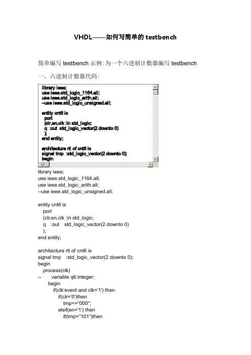
use ieee.std_logic_1164.all;use ieee.std_logic_arith.all;--use ieee.std_logic_unsigned.all;entity cnt6 isport(clr,en,clk :in std_logic;q :out std_logic_vector(2 downto 0) );end entity;architecture rtl of cnt6 issignal tmp :std_logic_vector(2 downto 0); beginprocess(clk)-- variable q6:integer;beginif(clk'event and clk='1') thenif(clr='0')thentmp<="000";elsif(en='1') thenif(tmp="101")thentmp<="000";elsetmp<=unsigned(tmp)+'1';end if;end if;end if;q<=tmp;-- qa<=q(0);-- qb<=q(1);-- qc<=q(2);end process;end rtl;二、六进制计数器testbench的代码signal en :std_logic:='0';signal clk :std_logic:='0';signal q :std_logic_vector(2 downto 0);constant clk_period :time :=20 ns;begininstant:cnt6 port map(clk=>clk,en=>en,clr=>clr,q=>q);clk_gen:processbeginwait for clk_period/2;clk<='1';wait for clk_period/2;clk<='0';end process;clr_gen:processbeginclr<='0';wait for 30 ns;clr<='1';wait;end process;en_gen:processbeginen<='0';wait for 50ns;en<='1';wait;end process;end rtl;--测试平台文件(testbench)的基本结构library ieee;use ieee.std_logic_1164.all;entity test_bench is --测试平台文件的空实体(不需要端口定义) end test_bench;architecture tb_behavior of test_bench iscomponent entity_under_test --被测试元件的声明port(list-of-ports-theri-types-and-modes);end component;begininstantiation:entity_under_test port map(port-associations);process() --产生时钟信号……end process;process() --产生激励源……end process;end tb_behavior;------------------------------------------------------------------- --简单计数程序源码library ieee;use ieee.std_logic_1164.all;use ieee.std_logic_unsigned.all;use ieee.std_logic_unsigned.all;entity sim_counter isport(clk :in std_logic;reset :in std_logic;count :out std_logic_vector(3 downto 0));end entity;architecture behavioral of sim_counter issignal temp :std_logic_vector(3 downto 0);beginprocess(clk,reset)beginif reset='1' thentemp<="0000";elsif clk'event and clk='1' thentemp<=temp+1;end if;end process;count<=temp;end behavioral;------------------------------------------------------------------- --简单计数程序,测试文件代码(testbench)library ieee;use ieee.std_logic_1164.all;use ieee.std_logic_unsigned.all;use ieee.numeric_std.all;entity counter_tb_vhd is --测试平台实体end counter_tb_vhd;architecture behavior of counter_tb_vhd is--被测试元件(DUT)的声明component sim_counterport(clk :in std_logic;reset :in std_logic;count :out std_logic_vector(3 downto 0));end component;--输入信号signal clk:std_logic:='0';signal reset :std_logic:='0';--输出信号signal count :std_logic_vector(3 downto 0);constant clk_period :time :=20 ns; --时钟周期的定义begindut:sim_counter port map(clk=>clk,reset=>reset,counter=>counter);clk_gen:processbeginclk='1';wait for clk_period/2;clk='0';wait for clk_period/2;end process;tb:process --激励信号beginwait for 20 ns;reset<='1';wait for 20 ns;reset<='0';wait for 200 ns;wait; --will wait forever;end process;end;--激励信号的产生方式--1.以一定的离散时间间隔产生激励信号的波形--2.基于实体的状态产生激励信号,也就是说基于实体的输出响应产生激励信号--两种常用的复位信号--1.周期性的激励信号,如时钟--2.时序变化的激励型号,如复位--eg.产生不对称时钟信号w_clk<='0' after period/4 when w_clk='1' else'1' after 3*period/4 when w_clk='0' else'0';--eg.产生堆成时钟信号,process语句clk_gen1:processconstan clk_period := 40 ns;beginclk='1';wait for clk_period/2;clk='0';wait for clk_period/2;end process;四、如果自己不想写这些testbench的这些固定格式,可以在quartus 里自动生成testbench文件的模板,然后往里面写信号就行了步骤:processing->start->start test bench template write这里需要注意的是要在仿真选项里选择一个仿真工具,然后才会生成testbench自动生成的testbench模板格式如下:-- Copyright (C) 1991-2008 Altera Corporation-- Your use of Altera Corporation's design tools, logic functions-- and other software and tools, and its AMPP partner logic-- functions, and any output files from any of the foregoing-- (including device programming or simulation files), and any-- associated documentation or information are expressly subject-- to the terms and conditions of the Altera Program License-- Subscription Agreement, Altera MegaCore Function License-- Agreement, or other applicable license agreement, including,-- without limitation, that your use is for the sole purpose of-- programming logic devices manufactured by Altera and sold by-- Altera or its authorized distributors. Please refer to the-- applicable agreement for further details.-- ***************************************************************************-- This file contains a Vhdl test bench template that is freely editable to-- suit user's needs .Comments are provided in each section to help the user -- fill out necessary details.-- ***************************************************************************-- Generated on "03/13/2011 20:05:04"-- Vhdl Test Bench template for design : cnt6---- Simulation tool : ModelSim (VHDL)--LIBRARY ieee;USE ieee.std_logic_1164.all;ENTITY cnt6_vhd_tst ISEND cnt6_vhd_tst;ARCHITECTURE cnt6_arch OF cnt6_vhd_tst IS-- constants-- signalsSIGNAL clk : STD_LOGIC;SIGNAL clr : STD_LOGIC;SIGNAL en : STD_LOGIC;SIGNAL q : STD_LOGIC_VECTOR(2 DOWNTO 0);COMPONENT cnt6PORT (clk : IN STD_LOGIC;clr : IN STD_LOGIC;en : IN STD_LOGIC;q : OUT STD_LOGIC_VECTOR(2 DOWNTO 0));END COMPONENT;BEGINi1 : cnt6PORT MAP (-- list connections between master ports and signalsclk => clk,clr => clr,en => en,q => q);init : PROCESS-- variable declarationsBEGIN-- code that executes only onceWAIT;END PROCESS init;always : PROCESS-- optional sensitivity list-- ( )-- variable declarationsBEGIN-- code executes for every event on sensitivity list WAIT;END PROCESS always;END cnt6_arch;。
VHDL——如何写简单的testbench
use ieee.std_logic_1164.all;use ieee.std_logic_arith.all;--use ieee.std_logic_unsigned.all;entity cnt6 isport(clr,en,clk :in std_logic;q :out std_logic_vector(2 downto 0) );end entity;architecture rtl of cnt6 issignal tmp :std_logic_vector(2 downto 0); beginprocess(clk)-- variable q6:integer;beginif(clk'event and clk='1') thenif(clr='0')thentmp<="000";elsif(en='1') thenif(tmp="101")thentmp<="000";elsetmp<=unsigned(tmp)+'1';end if;end if;end if;q<=tmp;-- qa<=q(0);-- qb<=q(1);-- qc<=q(2);end process;end rtl;二、六进制计数器testbench的代码signal en :std_logic:='0';signal clk :std_logic:='0';signal q :std_logic_vector(2 downto 0);constant clk_period :time :=20 ns;begininstant:cnt6 port map(clk=>clk,en=>en,clr=>clr,q=>q);clk_gen:processbeginwait for clk_period/2;clk<='1';wait for clk_period/2;clk<='0';end process;clr_gen:processbeginclr<='0';wait for 30 ns;clr<='1';wait;end process;en_gen:processbeginen<='0';wait for 50ns;en<='1';wait;end process;end rtl;--测试平台文件(testbench)的基本结构library ieee;use ieee.std_logic_1164.all;entity test_bench is --测试平台文件的空实体(不需要端口定义) end test_bench;architecture tb_behavior of test_bench iscomponent entity_under_test --被测试元件的声明port(list-of-ports-theri-types-and-modes);end component;begininstantiation:entity_under_test port map(port-associations);process() --产生时钟信号……end process;process() --产生激励源……end process;end tb_behavior;------------------------------------------------------------------- --简单计数程序源码library ieee;use ieee.std_logic_1164.all;use ieee.std_logic_unsigned.all;use ieee.std_logic_unsigned.all;entity sim_counter isport(clk :in std_logic;reset :in std_logic;count :out std_logic_vector(3 downto 0));end entity;architecture behavioral of sim_counter issignal temp :std_logic_vector(3 downto 0);beginprocess(clk,reset)beginif reset='1' thentemp<="0000";elsif clk'event and clk='1' thentemp<=temp+1;end if;end process;count<=temp;end behavioral;------------------------------------------------------------------- --简单计数程序,测试文件代码(testbench)library ieee;use ieee.std_logic_1164.all;use ieee.std_logic_unsigned.all;use ieee.numeric_std.all;entity counter_tb_vhd is --测试平台实体end counter_tb_vhd;architecture behavior of counter_tb_vhd is--被测试元件(DUT)的声明component sim_counterport(clk :in std_logic;reset :in std_logic;count :out std_logic_vector(3 downto 0));end component;--输入信号signal clk:std_logic:='0';signal reset :std_logic:='0';--输出信号signal count :std_logic_vector(3 downto 0);constant clk_period :time :=20 ns; --时钟周期的定义begindut:sim_counter port map(clk=>clk,reset=>reset,counter=>counter);clk_gen:processbeginclk='1';wait for clk_period/2;clk='0';wait for clk_period/2;end process;tb:process --激励信号beginwait for 20 ns;reset<='1';wait for 20 ns;reset<='0';wait for 200 ns;wait; --will wait forever;end process;end;--激励信号的产生方式--1.以一定的离散时间间隔产生激励信号的波形--2.基于实体的状态产生激励信号,也就是说基于实体的输出响应产生激励信号--两种常用的复位信号--1.周期性的激励信号,如时钟--2.时序变化的激励型号,如复位--eg.产生不对称时钟信号w_clk<='0' after period/4 when w_clk='1' else'1' after 3*period/4 when w_clk='0' else'0';--eg.产生堆成时钟信号,process语句clk_gen1:processconstan clk_period := 40 ns;beginclk='1';wait for clk_period/2;clk='0';wait for clk_period/2;end process;四、如果自己不想写这些testbench的这些固定格式,可以在quartus 里自动生成testbench文件的模板,然后往里面写信号就行了步骤:processing->start->start test bench template write这里需要注意的是要在仿真选项里选择一个仿真工具,然后才会生成testbench自动生成的testbench模板格式如下:-- Copyright (C) 1991-2008 Altera Corporation-- Your use of Altera Corporation's design tools, logic functions-- and other software and tools, and its AMPP partner logic-- functions, and any output files from any of the foregoing-- (including device programming or simulation files), and any-- associated documentation or information are expressly subject-- to the terms and conditions of the Altera Program License-- Subscription Agreement, Altera MegaCore Function License-- Agreement, or other applicable license agreement, including,-- without limitation, that your use is for the sole purpose of-- programming logic devices manufactured by Altera and sold by-- Altera or its authorized distributors. Please refer to the-- applicable agreement for further details.-- ***************************************************************************-- This file contains a Vhdl test bench template that is freely editable to-- suit user's needs .Comments are provided in each section to help the user -- fill out necessary details.-- ***************************************************************************-- Generated on "03/13/2011 20:05:04"-- Vhdl Test Bench template for design : cnt6---- Simulation tool : ModelSim (VHDL)--LIBRARY ieee;USE ieee.std_logic_1164.all;ENTITY cnt6_vhd_tst ISEND cnt6_vhd_tst;ARCHITECTURE cnt6_arch OF cnt6_vhd_tst IS-- constants-- signalsSIGNAL clk : STD_LOGIC;SIGNAL clr : STD_LOGIC;SIGNAL en : STD_LOGIC;SIGNAL q : STD_LOGIC_VECTOR(2 DOWNTO 0);COMPONENT cnt6PORT (clk : IN STD_LOGIC;clr : IN STD_LOGIC;en : IN STD_LOGIC;q : OUT STD_LOGIC_VECTOR(2 DOWNTO 0));END COMPONENT;BEGINi1 : cnt6PORT MAP (-- list connections between master ports and signalsclk => clk,clr => clr,en => en,q => q);init : PROCESS-- variable declarationsBEGIN-- code that executes only onceWAIT;END PROCESS init;always : PROCESS-- optional sensitivity list-- ( )-- variable declarationsBEGIN-- code executes for every event on sensitivity list WAIT;END PROCESS always;END cnt6_arch;。
Testbench写法总结
outer_port_tb_wire,inner_port_tb_wire);
end
else
begin
$display("\n **** time=%t ****",$time);
$display("ERROR! out_en=%d",out_en_tb);
$display("ERROR! outer_port_tb_wire != inner_port_tb_wire" );
$display("ERROR! outer_port_tb_wire=%d, inner_port_tb_wire=%d",
outer_port_tb_wire,inner_port_tb_wire);
end
end
endmodule
验证该双向端口的testbench结构如图2所示。
这是一个self-checking testbench,可以自动检查仿真结果是否正确,并在Modelsim控制台上打印出提示信息。图中Monitor完成信号采样、结果自动比较的功能。
testbench的工作过程为
1)out_en=1时,双向端口处于输出状态,testbench给inner_port_tb_reg信号赋值,然后读取outer_port_tb_wire的值,如果两者一致,双向端口工作正常。
module tb();
reg[7:0] inner_port_tb_reg;
wire[7:0] inner_port_tb_wire;
reg[7:0] outer_port_tb_reg;
wire[7:0] outer_port_tb_wire;
简单的Testbench设计

//被测设计的输入信号,对应测试脚本的输出信号(注意要定义成 reg) reg clk; reg rst_n; //被测设计的输出信号,对应测试脚本的输入信号(注意要定义成 wire) wire led; //例化待测模块 Led led_test
简单的 Testbench nch 是一种验证的手段。首先,任何设计都是会有输入输出的。 但是在软环境中没有激励输入,也不会对你设计的输出正确性进行评估。那 幺此时便有一种,模拟实际环境的输入激励和输出校验的一种“虚拟平台”的 产生。在这个平台上你可以对你的设计从软件层面上进行分析和校验,这个 就是 testbench 的含义。 简单的 Testbench 设计 //timescale 仿真时间单位/时间精度(时间精度不能比时间单位还要 大) timescale 1ns/1ps //定义一个无输入无输出的 Moudle module Led_clg_tst();
( .clk(clk), .rst_n(rst_n), .led(led) ); //使用 Initail 生成 rst_n 激励 initial begin //监控 Led 信号变化
monitor(monitor(time,”led value= %b\n”,led); end //使用 alwasys 模拟产生 25M 的时钟信号 always #20 clk = ~clk; endmodule
我的testbench书写总结

占空比为 50%的时钟`timescale 1ns/1ns //定义时间的尺度和精度,其中精度和小树部分挂钩parameter period=4’d10;reg clk; //时钟是输入给DUT的信号必须声明为reg类型initialbeginclk=1’b0; //定义clk的初始状态为低电平forever#( period/2) clk=~clk;endparameter period=4’d10;reg clk;initialbeginclk=1’b0; //定义clk的初始状态为低电平endalways #( period/2) clk=~clk;占空比非50%的时钟信号parameter HIGH_TIME=4,LOW_TIME=6;reg clk;initialbeginclk=1’b0; //定义clk的初始状态为低电平endalwaysbegin# LOW_TIME clk=1’b1;//0~LOW_TIME为低电平# HIGH_TIME clk=1’b0; //从low_time~(low_time+high_time)为高电平end固定数目的时钟信号parameter PulseCount=4,PERIOD=10;reg clk;initialbeginclk=1’b0; //定义clk的初始状态为低电平repeat(PulseCount) //相对于下面的语句重复执行4次#(PERIOD/2) clk=~clk;End//先低电平半个周期,然后再产生两个完整周期的脉冲,结束时clk为低电平parameter Phase_Shift=2;PERIOD=10;reg source_clk;wire derive_clk;//这里是wire好像没有多大用处,要是能用reg就有用了//用initial语句生成源时钟initialbeginclk=1’b0; //定义clk的初始状态为低电平forever#( PERIOD/2) source_clk=~source_clk;EndAssign #Phase_Shift derive_clk=source_clk; //生成派生时钟,要延后2ns2,对于仿真器,reg在没有赋初始值的情况下默认的值为’X’即不定值,而wire的默认值为’Z’即高阻态。
怎样写testbench
怎样写testbench本文的实际编程环境:ISE 6.2i.03ModelSim 5.8 SESynplify Pro 7.6编程语言 VHDL在ISE中调用ModelSim进行仿真一、基本概念和基础知识Testbench不仅要产生激励也就是输入,还要验证响应也就是输出。
当然也可以只产生激励,然后通过波形窗口通过人工的方法去验证波形,这种方法只能适用于小规模的设计。
在ISE环境中,当前资源操作窗显示了资源管理窗口中选中的资源文件能进行的相关操作。
在资源管理窗口选中了testbench文件后,在当前资源操作窗显示的ModelSim Simulator中显示了4种能进行的模拟操作,分别是:Simulator Behavioral Model(功能仿真)、Simulator Post-translate VHDL Model(翻译后仿真)、Simulator Post-Map VHDL Model(映射后仿真)、Simulator Post-Place & Route VHDL Model(布局布线后仿真)。
如图1所示:图1l Simulator Behavioral Model 也就是所说的功能仿真、行为仿真、前仿真。
验证功能是否正确,这是设计的第一步。
功能仿真正确的程序不一定能被正确综合,也就是硬件实现。
有的在综合时报错误,有的虽然能综合但结果并不正确。
当然,功能仿真如果都不能通过,以后的步骤也就无法进行。
这是必做的仿真。
l Simulator Post-translate VHDL Model 也就是翻译后仿真。
对源程序进行编译后首先排除了语法错误,对一些像类属命令(Generic)、生成语句(Generate)等进行了展开。
不是必做的仿真。
l Simulator Post-Map VHDL Model也就是映射后仿真。
不同的器件内部结构也不尽相同,映射的作用就是将综合后产生的网表文件对应到实际的器件上去。
vivadotestbench写法
主题:vivadotestbench编写方法内容:1. 什么是vivadotestbench?vivadotestbench是一个用于编写Verilog的测试台,用于对Verilog 模块进行仿真和验证。
它可以帮助工程师们在Verilog设计的早期阶段进行功能验证和性能评估,以确保设计的稳定性和正确性。
2. vivadotestbench的基本结构vivadotestbench通常包含以下基本结构:模块实例化、时钟和复位初始化、输入数据生成、仿真控制和输出检测。
这些基本结构构成了一个完整的测试台,可以用于对Verilog模块进行全面的验证和测试。
3. vivadotestbench的编写步骤编写vivadotestbench的步骤可以分为以下几个部分:3.1 模块实例化:首先需要实例化待测模块,并且连接时钟、复位信号和输入输出端口。
3.2 时钟和复位初始化:在测试台中需要为待测模块提供时钟信号,并对复位信号进行初始化。
3.3 输入数据生成:根据待测模块的输入端口,生成相应的测试数据,并将其输入到待测模块中。
3.4 仿真控制:控制仿真的开始、暂停和结束,以及执行仿真的时长和步长等。
3.5 输出检测:对待测模块的输出进行检测和比对,以验证其正确性和稳定性。
4. vivadotestbench的常见问题及解决方法在编写vivadotestbench的过程中,可能会遇到一些常见的问题,例如时序约束不准确、测试数据生成不完整、输出检测逻辑错误等。
针对这些问题,可以采取一些解决方法,如优化时序约束、增加测试数据生成的覆盖率、修正输出检测逻辑等。
5. vivadotestbench的优点和应用场景vivadotestbench具有易用性好、灵活性强、功能全面等优点,适用于对Verilog模块进行全面的仿真和验证。
它可以帮助工程师们提高设计的稳定性和正确性,加快设计的上线速度,降低设计的风险和成本。
结论:vivadotestbench是一个强大的Verilog测试台,可以帮助工程师们在Verilog设计的早期阶段进行全面的功能验证和性能评估。
Testbench文件编写纪要(Verilog)
Testbench⽂件编写纪要(Verilog)之前在使⽤Verilog做FPGA项⽬中、以及其他⼀些不同的场合下,零散的写过⼀些练⼿性质的testbench⽂件,开始⼏次写的时候,每次都会因为⼀些基本的东西没记住、写的很不熟练,后⾯写的时候稍微熟练了⼀点、但是整体编写下来⽐较零碎不成体系,所以在这⾥简要记录⼀下⼀般情况下、针对⼩型的verilog模块进⾏测试时所需要使⽤到的testbench⽂件的编写要点。
本⽂主要参考了在⽹上找到的Lattice公司的“A Verilog HDL Test Bench Primer”⼿册中的有关内容。
谢谢!模块实例化、reg&wire声明、initial和always块的使⽤需要测试的模块(Verilog-module)被称为DUT(Design Under Test),在testbench中需要对⼀个或者多个DUT进⾏实例化。
Testbench中的顶层module不需要定义输⼊和输出。
Testbench中连接到DUT instance的输⼊的为reg类型、连接到DUT instance的输出的为wire类型。
对于DUT的inout类型变量,在testbench中需要分别使⽤reg、wire类型的变量进⾏调⽤。
例如,对于下⾯这样⼀个待测试module:module bidir_infer (DATA, READ_WRITE);input READ_WRITE ;inout [1:0] DATA ;reg [1:0] LATCH_OUT ;always @ (READ_WRITE or DATA) beginif (READ_WRITE == 1)LATCH_OUT <= DATA;endassign DATA = (READ_WRITE == 1) ? 2'bZ : LATCH_OUT;endmodule为其设计的testbench⽂件可以是:module test_bidir_ver;reg read_writet;reg [1:0] data_in;wire [1:0] datat, data_out;bidir_infer uut (datat, read_writet);assign datat = (read_writet == 1) ? data_in : 2'bZ;assign data_out = (read_writet == 0) ? datat : 2'bZ;initial beginread_writet = 1;data_in = 11;#50 read_writet = 0;endendmodule和普通的Verilog模块中⼀样、使⽤assign对wire类型的变量进⾏赋值。
(完整版)实例解读Testbench编写方法
实例解读Testbench编写方法前言:在进行quartusII设计时,不少人刚开始觉得仿真极其不方便,还需要编写测试文件,浪费时间精力。
不过小编想告诉大家,其实testbench编写很容易学,不外乎wait for 语句的堆叠就可以了,至于高深的用法,对一般程序都涉及不到,没必要弄得那么复杂。
下面看看实例吧,将详细说明testbench的编写:我们可以通过Quartus自动生成一个Testbench的模板,选择Processing —〉 Start -〉Start Test Bench Template Writer,等待完成后打开刚才生成的Testbench,默认是保存在sim ulation\modelsim文件夹下的.vt格式文件.打开vt文件后可以看到Quartus已经为我们完成了一些基本工作,包括端口部分的代码和接口变量的声明,我们要做的就是在这个做好的模具里添加我们需要的测试代码.一个最基本的Testbench包含三个部分,信号定义、模块接口和功能代码.‘timescale 1ns/ 1ps表示仿真的单位时间为1ns,精度为1ps.想要进行仿真首先要规定时间单位,而且最好在Testbench里面统一规定时间单位,而不要在工程代码里定义,因为不同的模块如果时间单位不同可能会为仿真带来一些问题,而timescale本身对综合也就是实际电路没有影响。
其实Testbench本身可以看做一个模块或者设备(本例中的模块名为add_vlg_tst),和你自己编写的模块进行通信。
通过Testbench模块向待测模块输出信号作为激励,同时接收从待测模块输出的信号来查看结果.因此,在待测模块中的reg型信号在Testbench中就变成了wire,待测模块中的wire型信号在Testb ench中则对应为reg型。
那么inout怎么办呢,inout型信号也要设成wire,同时要用一个reg型信号作为输出寄存器,同时设置一个三态门,由一个使能信号控制,如:assign inout_sig = out_en ? out_reg : 1’bz;处理完接口和声明之后,需要自己设置一些激励信号,激励信号的内容就是肯能会输入到待测模块中的波形.下面我们就来写一个简单的测试程序.实例:60进制计数器源代码:library ieee;use ieee.std_logic_1164。
- 1、下载文档前请自行甄别文档内容的完整性,平台不提供额外的编辑、内容补充、找答案等附加服务。
- 2、"仅部分预览"的文档,不可在线预览部分如存在完整性等问题,可反馈申请退款(可完整预览的文档不适用该条件!)。
- 3、如文档侵犯您的权益,请联系客服反馈,我们会尽快为您处理(人工客服工作时间:9:00-18:30)。
怎样写testbench本文的实际编程环境:ISE 6.2i.03ModelSim 5.8 SESynplify Pro 7.6编程语言 VHDL在ISE中调用ModelSim进行仿真一、基本概念和基础知识Testbench不仅要产生激励也就是输入,还要验证响应也就是输出。
当然也可以只产生激励,然后通过波形窗口通过人工的方法去验证波形,这种方法只能适用于小规模的设计。
在ISE环境中,当前资源操作窗显示了资源管理窗口中选中的资源文件能进行的相关操作。
在资源管理窗口选中了testbench文件后,在当前资源操作窗显示的ModelSim Simulator中显示了4种能进行的模拟操作,分别是:Simulator Behavioral Model(功能仿真)、Simulator Post-translate VHDL Model(翻译后仿真)、Simulator Post-Map VHDL Model(映射后仿真)、Simulator Post-Place & Route VHDL Model(布局布线后仿真)。
如图1所示:图1l Simulator Behavioral Model 也就是所说的功能仿真、行为仿真、前仿真。
验证功能是否正确,这是设计的第一步。
功能仿真正确的程序不一定能被正确综合,也就是硬件实现。
有的在综合时报错误,有的虽然能综合但结果并不正确。
当然,功能仿真如果都不能通过,以后的步骤也就无法进行。
这是必做的仿真。
l Simulator Post-translate VHDL Model 也就是翻译后仿真。
对源程序进行编译后首先排除了语法错误,对一些像类属命令(Generic)、生成语句(Generate)等进行了展开。
不是必做的仿真。
l Simulator Post-Map VHDL Model也就是映射后仿真。
不同的器件内部结构也不尽相同,映射的作用就是将综合后产生的网表文件对应到实际的器件上去。
由于映射不包含布线,也就是要用什么类型的逻辑单元虽然已经确定但要用哪个位置的还没有确定,因此,映射后仿真不包含布线延时。
不是必做的仿真。
l Simulator Post-Place & Route VHDL Model也就是所说的布局布线后仿真、时序仿真、后仿真。
这是最完整的仿真,既包含逻辑延时又包含布线延时。
在做布局布线后仿真时要用到一个叫SDF的文件。
SDF文件包含设计中每个单元(Cell)的延时和时序约束数据。
通过加载这个文件就能得到完整的时序情况。
它是必做的仿真。
一般必须进行功能仿真和布局布线后仿真。
常见问题:为什么有的testbench在进行功能仿真时能正确进行,而在进行布局布线后仿真时就不能运行。
有两点要注意的地方:(1)、在做映射后仿真或布局布线后仿真时,都已经经过了综合工具的综合,源程序中的类属命令(Generic)、生成语句(Generate)等都已经进行展开。
例如,如果用Generic定义了一个参数width,综合工具进行综合时已经按照一个确定的width值进行了综合。
它生成的电路已经具有一个确定的结构,不能再随意调整。
所以在映射后仿真和布局布线后仿真的testbench中,往往不能出现Generic语句。
(2)映射后仿真和布局布线后仿真都要用到SDF文件,并且要将SDF文件关联到设计中的实例。
所以在映射后仿真和布局布线后仿真的testbench中,第一,要将你的设计声明成一个元件。
第二,实例化你设计的元件并且实例名要取为UUT(默认的,当然也可以改)。
关于断言语句在仿真中为了能得到更多信息,经常要用到断言语句(assert)。
其语法如下:Assert<条件>Report<消息>Severity<出错级别>;出错级别共有5种:l Notel Warningl Errorl Failurel Fatal在VHDL模型的模拟过程中,一旦断言语句的条件为假,则发送消息并将出错级别发送给模拟器。
通常可以设置一个中止模拟器运行的出错级别,一般默认的中止运行的出错级别为Failure。
我们来看一个例子:assert falsereport "********* " & IMAGE(DWIDTH) & "BIT DIVIDER SEQUENCE FINISHEDAT " & IMAGE(now) & " !" & " *********"severity note;断言的条件不是一个条件表达式,而直接是false。
这说明只要程序执行到这里断言就一定会成立,送出消息。
出错级别为note,在模拟器的输出窗口将会显示:and (s_ovi = '0')and (s_qutnt = conv_std_logic_vector(v_quot,DWIDTH))and (s_rmndr = conv_std_logic_vector(v_remd,DWIDTH))report "ERROR in division!"severity failure;断言的条件有4个并且是与的关系,只要其中一个条件不成立则整个表达式为假,断言成立。
如果断言成立将输出“ERROR in division!“这个消息。
并且通知模拟器出错级别为failure,这一般会停止模拟。
这个断言实际是在对结果进行验证。
二、实际testbench分析下面将详细分析一个实际的testbench,它是用来测试8051的ALU单元的除法功能的。
8位的除法器,被除数和除数的组合共有256×256=65536种。
我们采用的方法是穷举所有的输入组合,这样的代码覆盖率可以达到100%。
它的验证必须通过程序自动完成,否则通过人工方法工作量太大。
把要测试的程序当作一个元件,例如想象成一个74系列数字电路。
Testbench的作用是在被测试电路的输入端加上激励,然后比较被测试电路的输出和计算出来的期望值是否一致。
对我们这个例子来说,在要仿真的ALU输入端产生65536种输入组合,然后将ALU产生的对应输出值和testbench算出的期望值相比较,如果有错误产生则停止模拟并输出信息。
ALU的除法单元的输入有4个,分别是被除数、除数、进位、溢出位;输出也有4个,分别是商、余数、新的进位、新的溢出位。
1、testbench的输出s_dvdnd(被除数)、s_dvsor(除数)、s_cyo(进位)、s_ovo(溢出位)连接到ALU的输入acc_i(被除数)、ram_data_i(除数)、cy_i(进位)、ov_i (溢出位);2、testbench的输入s_qutnt(商)、s_rmndr(余数)、s_cyi(进位)、s_ovi(溢出位)连接到ALU的输出result_a_o(商)、 result_b_o(余数)、new_cy_o(进位)、new_ov_o (溢出位)。
3、总之,testbench驱动被测试单元,同时对被测试单元的输出进行验证。
4、assert (s_cyi((DWIDTH-1)/4) = '0')and (s_ovi = '0')and (s_qutnt = conv_std_logic_vector(v_quot,DWIDTH))and (s_rmndr = conv_std_logic_vector(v_remd,DWIDTH))report "ERROR in division!"severity failure;根据51指令系统规定,除法运算的cy位固定为0,如果除数为0则ov置1,否则置0。
程序中s_qutnt = conv_std_logic_vector(v_quot,DWIDTH)s_rmndr = conv_std_logic_vector(v_remd,DWIDTH)用来对运算结果进行比较。
conv_std_logic_vector()是类型转换函数。
――首先是对库的引用library IEEE;use IEEE.std_logic_1164.all;use IEEE.std_logic_arith.all;library work;use work.mc8051_p.all;library STD;use STD.textio.all;――定义结构体,testbench程序的结构体是空的。
因为testbench是用来仿真的,不存在--对外的接口,所以entity是空的。
但是必须要有,这是语法的要求。
entity TBX_mc8051_alu isend TBX_mc8051_alu;------------------------------------------------------------------------------- architecture TBX_ARCH_DIV of TBX_mc8051_alu is――定义元件,映射后仿真和布局布线后仿真要使用SDF文件,必须指定实例名。
要实例--化元件首先必须定义元件。
component mc8051_aluport (new_ov_o : out STD_LOGIC; ――新的ov位,输出ov_i : in STD_LOGIC := 'X'; ――ov位,输入new_cy_o : out STD_LOGIC_VECTOR ( 1 downto 0 ); ――新的cy位,输出acc_i : in STD_LOGIC_VECTOR ( 7 downto 0 ); ――acc,输入rom_data_i : in STD_LOGIC_VECTOR ( 7 downto 0 ); ――rom_data,输入cmd_i : in STD_LOGIC_VECTOR ( 5 downto 0 ); ――命令,输入ram_data_i : in STD_LOGIC_VECTOR ( 7 downto 0 ); ――ram_data,输入cy_i : in STD_LOGIC_VECTOR ( 1 downto 0 ); ――cy,输入result_b_o : out STD_LOGIC_VECTOR ( 7 downto 0 ); ――结果b,输出result_a_o : out STD_LOGIC_VECTOR ( 7 downto 0 ) -―结果a,输出);end component;――定义函数----------------------------------------------------------------------------- ---- IMAGE - Convert a special data type to string -- --This function uses the STD.TEXTIO.WRITE procedure to convert different -- -- VHDL data types to a string to be able to output the information via -- -- a report statement to the simulator. -- -- (VHDL'93 provides a dedicated predefinded attribute 'IMAGE) -- ----------------------------------------------------------------------------- ――定义了一个函数IMAGE,之所以有两个定义,是因为对IMAGE进行了重载,一个是把――time变量转换成string,另一个是把integer变量转换成stringfunction IMAGE (constant tme : time) return string isbeginv_tme(v_line.all'range) := v_line.all;deallocate(v_line);return v_tme;end IMAGE;function IMAGE (constant nmbr : integer) return string isvariable v_line : line;variable v_nmbr : string(1 to 11) := (others => ' ');beginwrite(v_line, nmbr);v_nmbr(v_line.all'range) := v_line.all;deallocate(v_line);return v_nmbr;end IMAGE;――定义过程,它产生所有的测试输入数据并将产生结果和期望值进行比较,如果有误――产生,模拟将停止并输出一个错误信息。