VHDL_Testbench编写
加法器
深圳大学实验报告课程名称:VHDL数字电路设计教程实验项目名称:逐级进位加法器和超前进位加法器学院:信息工程学院专业:电子信息工程指导教师:邓小莺报告人:尹海德学号:2011130296 班级: 3 实验时间:2013-5-20实验报告提交时间:2013-5-31教务处制2:超前进位加法器Test banch-------------------------------------------------------------------------------- LIBRARY ieee;USE ieee.std_logic_1164.ALL;-- Uncomment the following library declaration if using-- arithmetic functions with Signed or Unsigned values--USE ieee.numeric_std.ALL;ENTITY LSJ_adder_for_m_test ISEND LSJ_adder_for_m_test;ARCHITECTURE behavior OF LSJ_adder_for_m_test IS -- Component Declaration for the Unit Under Test (UUT)COMPONENT LSJ_adde_for_mPORT(a : IN std_logic_vector(4 downto 0);三实验结论全面了解逐级进位加法器和超前进位加法器的工作原理。
加强了代码的编写能力,更加升入学习XILINX软件设计以及仿真。
深圳大学学生实验报告用纸注:1、报告内的项目或内容设置,可根据实际情况加以调整和补充。
2、教师批改学生实验报告时间应在学生提交实验报告时间后10日内。
编写高效率的testbench
编写高效率的testbench简介:由于设计的规模越来越大也越来越复杂,数字设计的验证已经成为一个日益困难和繁琐的任务。
验证工程师们依靠一些验证工具和方法来应付这个挑战。
对于几百万门的大型设计,工程师们一般使用一套形式验证(formal verification)工具。
然而对于一些小型的设计,设计工程师常常发现用带有testbench的HDL仿真器就可以很好地进行验证。
Testbench已经成为一个验证高级语言(HLL --High-Level Language) 设计的标准方法。
通常testbench完成如下的任务:1.实例化需要测试的设计(DUT);2.通过对DUT模型加载测试向量来仿真设计;3.将输出结果到终端或波形窗口中加以视觉检视;4.另外,将实际结果和预期结果进行比较。
通常testbench用工业标准的VHDL或Verilog硬件描述语言来编写。
Testbench调用功能设计,然后进行仿真。
复杂的testbench完成一些附加的功能—例如它们包含一些逻辑来选择产生合适的设计激励或比较实际结果和预期结果。
后续的章节描述了一个仔细构建的testbench的结构,并且提供了一个自动比较实际结果与预期结果的进行自我检查的testbench例子。
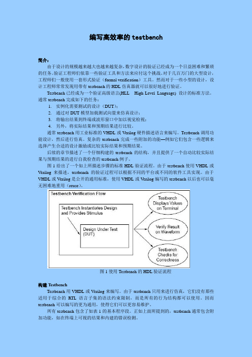
图1给出了一个如上所描述步骤的标准HDL验证流程。
由于testbench使用VHDL或Verilog来描述,testbench的验证过程可以根据不同的平台或不同的软件工具实现。
由于VHDL或Verilog是公开的通用标准,使用VHDL或Verilog编写的testbench以后也可以毫无困难地重用(reuse)。
图1使用Testbench的HDL验证流程构建TestbenchTestbench用VHDL或Verilog来编写。
由于testbench只用来进行仿真,它们没有那些适用于综合的RTL语言子集的语法约束限制,而是所有的行为结构都可以使用。
因而testbench可以编写的更为通用,使得它们可以更容易维护。
AD6 中VHDL设计及创建Testbench参考

VHDL语言设计参考VHDL是一种用于数字系统行为级描述的编程语言。
VHDL具备了许多适合于电子器件行为级描述的特性,无论是简单的逻辑门电路还是复杂的微处理器或用户自定制的器件。
从而,VHDL满足电路行为中电气特征(诸如信号上升/下降时间、门延迟和功能)的精确描述。
并且利用VHDL仿真模型可以搭建更大的可仿真电路。
VHDL还是一种通用的可编程语言,就如同利用高级语言在计算机上编写复杂的设计程序,VHDL允许输入复杂电子电路的行为级设计,并实现自动电路综合或系统仿真。
同时,VHDL也不同于高级语言,采用并发事件设计(即在执行阶段内,每个语句行为是并行执行的);这一特性取决于硬件电路设计上固有的并行执行的特性。
VHDL最重要的应用之一就是设计电路的执行规范,语法规则与Testbench相一致。
Testbench是用于验证电路在时间上行为级描述的。
在任何时候,Testbench都将作为VHDL 设计项目的一个组成部分。
注:符号 <=为付值操作符,表示将符号右边的数值给符号左边的变量;一个完整的VHDL设计项目至少要包含一个实体(entity)和结构体(architecture)定义。
对于一个大型设计,通常需要定义多个实体/结构对并且将他们连接在一起形成一个完整的电路。
实体定义用于描述电路的输入/输出端口;结构体定义是VHDL设计中最小的组成单元。
在仿真或综合执行前,每个实体必须被相对应结构体封装。
在结构体中描述了实际的功能。
实体定义entity comp_name isport(in_port : in bit_vector(7 downto 0); out_port : out bit);end comp_name;结构体定义:architecture comp_name of entity_name isbegin<conditional assignment>;end comp_name;注:关键字process用来封装复杂的顺序逻辑设计;VHDL语言中的数据类型:VHDL设计中实际由5种设计单元类型构成:实体、结构体、程序包、程序包体和配置。
testbench(框架—基础—进阶)

--------------------------------------project-------------------------------------------------------此模块为yuv444转yuv422模块,由输入24bit数转8bit输出,本笔记都以此工程为基础,都仿真测试过module yuv444to422(input ccd_clk,input sys_clk,input resetn,input HD,input VD,input [23:0] yuv,input yuv_trans_done,output clk_out,output reg [7:0] data_out,output HD_out,output VD_out,output reg [11:0] v_cnt);assign clk_out = ~ccd_clk;assign HD_out = HD;// ;hd1[1]assign VD_out = VD;//v_cnt_out;//;vd1[1]///////////////////1280*1024-->1280*720////////////reg [1:0] hs_edge;always@(posedge ccd_clk)beginif(!resetn)hs_edge <= 2'b00;elsehs_edge<= {hs_edge[0],HD};endalways@(posedge ccd_clk)beginif(!resetn)v_cnt <= 12'b0;else if(!VD)v_cnt <=0;else if(hs_edge==2'b01)v_cnt <= v_cnt +1;endreg v_cnt_out;always@(posedge sys_clk)beginif(!resetn)v_cnt_out <= 1'd0;else if ((v_cnt >= 12'd179) && (v_cnt <= 12'd899)) v_cnt_out <= 1'd1;else v_cnt_out <= 1'd0;end*/////////////////////////////reg [1:0]cnt1;always@(posedge ccd_clk)beginif(!resetn)cnt1<=0;else if(yuv_trans_done)cnt1<=cnt1+1;endalways@(posedge ccd_clk)beginif(!resetn)begindata_out <= 8'b0;endelse if (HD)begincase(cnt1)2'b0:data_out <= yuv[23:16];2'b1:data_out <= yuv[15:8]; //8'h80;//2'd2:data_out <= yuv[23:16];2'd3:data_out <= yuv[7:0]; //8'h80;//endcaseendendmodule--------------------------------------------testbench------------------------------------------- `timescale 1 ns/ 1 ps`include "D:/tangate_quartus/yuv444to422/yuv444to422.v"module yuv444to422_vlg_tst();reg HD;reg VD;reg ccd_clk;reg resetn;reg sys_clk;reg [23:0] yuv;reg yuv_trans_done;// wireswire HD_out;wire VD_out;wire clk_out;wire [7:0] data_out;wire [11:0] v_cnt;yuv444to422 i1 (.HD(HD),.HD_out(HD_out),.VD(VD),.VD_out(VD_out),.ccd_clk(ccd_clk),.clk_out(clk_out),.data_out(data_out),.resetn(resetn),.sys_clk(sys_clk),.v_cnt(v_cnt),.yuv(yuv),.yuv_trans_done(yuv_trans_done));//------------------------------------------------------------------------------------- parameter n = 10;//-------------------------------------------------------------------------------------initialbeginHD = 1'b0; // time 0 时刻VD = 1'b0;repeat(n)begin# 200 VD = 1'b1; // time 200repeat(10*n)begin#100 HD = 1'b1; //time 300#100 HD = 1'b0; //time 700end#100 VD = 1'b0;endend//------------------------------------------------initialbeginyuv_trans_done = 1'b0;#30 yuv_trans_done = 1'b1;end//----------------------------------------------/*initialbeginresetn = 1'b0;#30 resetn = 1'b1;end*///---------------------------------------------initialbeginsys_rst (100);//复位100个时间单位endtask sys_rst ;input [10:0] rst_time; //调用task的时候,将参数赋值给rst_time beginresetn = 0;#rst_time;resetn = 1;endendtask//-----------------------------------------------------alwaysbegin#10 ccd_clk = 1'b0;#10 ccd_clk = 1'b1;endinitialbeginyuv = 24'b0;forever @(posedge ccd_clk) #20 yuv = $random;end//-----------------------------------------------------------initialbegin#10000 $stop(2);end//------------------------------ok---------------------------------/*initialbegin#3000begin$display("current scope is %m");$display("the signal is %s",data_out);$display("the time is %t",$time) ;$display("data_out has %c ascii character value",data_out);$display("data_out=%h hex %d decimal", data_out, data_out);$display("data_out=%o otal %b binary", data_out, data_out);endend*///--------------------------------------ok------------------------------------------//always @(data_out) $display("Output changed at %t to %b",$time,data_out); //---------------------------------ok---------------------------------------------------//always @(data_out) $strobe("Output changed at %t to %b",$time,data_out); //-------------------------------ok----------------------------------------------------//initial//$monitor ("at time is %t and the signal is %b\n",$time , VD_out) ;//----------------------------------ok------------------------------------//initial// $monitor ("%d is changed at %t",data_out,$time);//yuv444to422_vlg_tst. //-----------------------------------ok--------------------------------------/* reg [23:0] buffer;initialbuffer = 24'b0000_1110_0001_1011_0101_1100;always @ ( posedge ccd_clk) #10 {yuv,buffer} = {buffer,yuv};*///-------------------------------------ok---------------------------------------------/*always @ (ccd_clk)begin$timeformat(-9,1,"ns",0);$display ("time clk HD VD v_cnt data_out ");$monitor("%t %b %b %b %b %b ", $realtime, clk_out, HD_out, VD_out, v_cnt, data_out);end*///--------------------------------write ok--------------------------------------/*initialbegin : blockinteger file_id;file_id = $fopen("D:/tangate_quartus/yuv444to422/data_out.txt");//1.打开文件//$fmonitor只要有变化就一直记录自动换行无需加\n//格式:$fmonitor(file_id, "%format_char", parameter);$fmonitor(file_id, "%m: %t data_out=%d v_cnt=%h___tangate", $time, data_out, v_cnt);//$fwrite需要触发条件才记录,只记录一行数据,换行需加\n,注意反斜杠的方向$fwrite(file_id, "%m: time is %t**data_out=%d**v_cnt=%h\n", $time, data_out, v_cnt);//2.写入文件//$fdisplay需要触发条件才记录,只记录一行数据,自动换行无需加\n//格式:$fdisplay(file_id, "%format_char", parameter);$fdisplay (file_id, "%m: %t data_out=%d v_cnt=%h___great man", $time, data_out, v_cnt);$fclose("D:/tangate_quartus/yuv444to422/data_out.txt"); //3.关闭文件end*///-----------------------------------read ok----------------------------------------------begin : blockinteger file_id;file_id = $fopen("D:/tangate_quartus/yuv444to422/data_out.txt");//1.打开文件$fread( "D:/tangate_quartus/yuv444to422/data_out.txt", $time, data_out, v_cnt);//2.读取文件$fclose("D:/tangate_quartus/yuv444to422/data_out.txt"); //3.关闭文件endendmoduleTestbench 学习笔记(框架)为什么C不能取代verilog和VHDL作为硬件描述语言?因为C缺少了硬件描述最基本的三个思想:连通性(Connectivity),时间性(Time)和并行性(Concurrency)。
VHDL——如何写简单的testbench
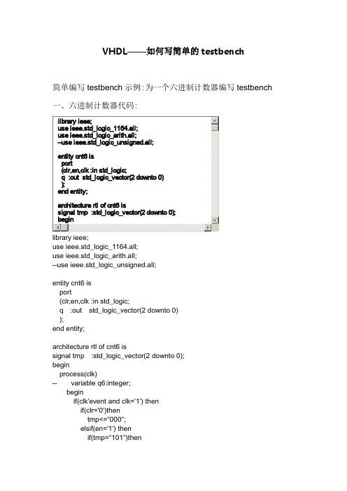
use ieee.std_logic_1164.all;use ieee.std_logic_arith.all;--use ieee.std_logic_unsigned.all;entity cnt6 isport(clr,en,clk :in std_logic;q :out std_logic_vector(2 downto 0) );end entity;architecture rtl of cnt6 issignal tmp :std_logic_vector(2 downto 0); beginprocess(clk)-- variable q6:integer;beginif(clk'event and clk='1') thenif(clr='0')thentmp<="000";elsif(en='1') thenif(tmp="101")thentmp<="000";elsetmp<=unsigned(tmp)+'1';end if;end if;end if;q<=tmp;-- qa<=q(0);-- qb<=q(1);-- qc<=q(2);end process;end rtl;二、六进制计数器testbench的代码signal en :std_logic:='0';signal clk :std_logic:='0';signal q :std_logic_vector(2 downto 0);constant clk_period :time :=20 ns;begininstant:cnt6 port map(clk=>clk,en=>en,clr=>clr,q=>q);clk_gen:processbeginwait for clk_period/2;clk<='1';wait for clk_period/2;clk<='0';end process;clr_gen:processbeginclr<='0';wait for 30 ns;clr<='1';wait;end process;en_gen:processbeginen<='0';wait for 50ns;en<='1';wait;end process;end rtl;--测试平台文件(testbench)的基本结构library ieee;use ieee.std_logic_1164.all;entity test_bench is --测试平台文件的空实体(不需要端口定义) end test_bench;architecture tb_behavior of test_bench iscomponent entity_under_test --被测试元件的声明port(list-of-ports-theri-types-and-modes);end component;begininstantiation:entity_under_test port map(port-associations);process() --产生时钟信号……end process;process() --产生激励源……end process;end tb_behavior;------------------------------------------------------------------- --简单计数程序源码library ieee;use ieee.std_logic_1164.all;use ieee.std_logic_unsigned.all;use ieee.std_logic_unsigned.all;entity sim_counter isport(clk :in std_logic;reset :in std_logic;count :out std_logic_vector(3 downto 0));end entity;architecture behavioral of sim_counter issignal temp :std_logic_vector(3 downto 0);beginprocess(clk,reset)beginif reset='1' thentemp<="0000";elsif clk'event and clk='1' thentemp<=temp+1;end if;end process;count<=temp;end behavioral;------------------------------------------------------------------- --简单计数程序,测试文件代码(testbench)library ieee;use ieee.std_logic_1164.all;use ieee.std_logic_unsigned.all;use ieee.numeric_std.all;entity counter_tb_vhd is --测试平台实体end counter_tb_vhd;architecture behavior of counter_tb_vhd is--被测试元件(DUT)的声明component sim_counterport(clk :in std_logic;reset :in std_logic;count :out std_logic_vector(3 downto 0));end component;--输入信号signal clk:std_logic:='0';signal reset :std_logic:='0';--输出信号signal count :std_logic_vector(3 downto 0);constant clk_period :time :=20 ns; --时钟周期的定义begindut:sim_counter port map(clk=>clk,reset=>reset,counter=>counter);clk_gen:processbeginclk='1';wait for clk_period/2;clk='0';wait for clk_period/2;end process;tb:process --激励信号beginwait for 20 ns;reset<='1';wait for 20 ns;reset<='0';wait for 200 ns;wait; --will wait forever;end process;end;--激励信号的产生方式--1.以一定的离散时间间隔产生激励信号的波形--2.基于实体的状态产生激励信号,也就是说基于实体的输出响应产生激励信号--两种常用的复位信号--1.周期性的激励信号,如时钟--2.时序变化的激励型号,如复位--eg.产生不对称时钟信号w_clk<='0' after period/4 when w_clk='1' else'1' after 3*period/4 when w_clk='0' else'0';--eg.产生堆成时钟信号,process语句clk_gen1:processconstan clk_period := 40 ns;beginclk='1';wait for clk_period/2;clk='0';wait for clk_period/2;end process;四、如果自己不想写这些testbench的这些固定格式,可以在quartus 里自动生成testbench文件的模板,然后往里面写信号就行了步骤:processing->start->start test bench template write这里需要注意的是要在仿真选项里选择一个仿真工具,然后才会生成testbench自动生成的testbench模板格式如下:-- Copyright (C) 1991-2008 Altera Corporation-- Your use of Altera Corporation's design tools, logic functions-- and other software and tools, and its AMPP partner logic-- functions, and any output files from any of the foregoing-- (including device programming or simulation files), and any-- associated documentation or information are expressly subject-- to the terms and conditions of the Altera Program License-- Subscription Agreement, Altera MegaCore Function License-- Agreement, or other applicable license agreement, including,-- without limitation, that your use is for the sole purpose of-- programming logic devices manufactured by Altera and sold by-- Altera or its authorized distributors. Please refer to the-- applicable agreement for further details.-- ***************************************************************************-- This file contains a Vhdl test bench template that is freely editable to-- suit user's needs .Comments are provided in each section to help the user -- fill out necessary details.-- ***************************************************************************-- Generated on "03/13/2011 20:05:04"-- Vhdl Test Bench template for design : cnt6---- Simulation tool : ModelSim (VHDL)--LIBRARY ieee;USE ieee.std_logic_1164.all;ENTITY cnt6_vhd_tst ISEND cnt6_vhd_tst;ARCHITECTURE cnt6_arch OF cnt6_vhd_tst IS-- constants-- signalsSIGNAL clk : STD_LOGIC;SIGNAL clr : STD_LOGIC;SIGNAL en : STD_LOGIC;SIGNAL q : STD_LOGIC_VECTOR(2 DOWNTO 0);COMPONENT cnt6PORT (clk : IN STD_LOGIC;clr : IN STD_LOGIC;en : IN STD_LOGIC;q : OUT STD_LOGIC_VECTOR(2 DOWNTO 0));END COMPONENT;BEGINi1 : cnt6PORT MAP (-- list connections between master ports and signalsclk => clk,clr => clr,en => en,q => q);init : PROCESS-- variable declarationsBEGIN-- code that executes only onceWAIT;END PROCESS init;always : PROCESS-- optional sensitivity list-- ( )-- variable declarationsBEGIN-- code executes for every event on sensitivity list WAIT;END PROCESS always;END cnt6_arch;。
test bench 教程

最近项目上要用到FPGA,之前用的一直是verilog,后面换成了VHDL。
对ISE一窍不通啊,研究了一些testbench文件的编写,record一下。
借用一下博文/lovelink/item/ff34ce9b12f45988581461ac的话。
首先对TESTBENCH作一个形象一些的比喻吧,它就象是一个面包板(做过电路实验吧),他对外没有任何接口,但它要向要插在他上面的器件提供接口,这样才能正确的插入,还有它必须对插在它上面的器件提供正常的信号。
当然在它上面还必须要有这个器件。
这时就完成了一个TESTBENCH。
应该大概明白了其中的意思了吧。
好了,根据上面的比喻我们可以非常明确的知道一个TESTBENCH要写一些什么东西,首先它对外无接口,所以它的实体部分是空的。
在它上面要有相应的器件,所以在它的结构体中要申明我们要测试的器件,也就是component的申明。
还有就是它要对器件提供接口,所以它的结构体应该提供一些信号,并且要对这些信号进行正确的测试赋值。
当然还要进行一些插入工作,就是信号的对应工作。
这样一个TESTBENCH就完成了。
原理很简单的,应该很容易明白。
不过在真正的测试中可能不会用太多的这种方式吧,应该会选用测试向量吧,这个的准确性更高一些。
不过怎么样写测试向量,这到是一个有大学问的东西,因为当我们的管脚很多的时候,测试的向量数目是要心指数增长的,当然不可能把所有的情况都测试完成了,只有是测试其中的一部分,这儿怎么样写出有代表性的一组测试向量是很有学问的,应该说是研究的热点吧。
几个testbench要用到的重要语句:(1)wait:无限等待,表示永远挂起,对于汉语wait语句的进程来说,进程在一开始执行一次后面就不执行了;(2)wait on 信号表:敏感信号等待语句,等待敏感信号表中的信号发生变化才执行;(3)wait until 表达式:条件等待语句,当条件表达式中所含的信号发生了变化,并为true时,进程才脱离等待状态;(4)wait for 时间表达式:此语句中声明了一个时间段,从从执行到当前的wait语句开始,只要这个时间段内,进程处于等待状态,超过这段时间,进程自动恢复执行该等待语句的下一条语句。
VHDL Test bench文件的三种生成方式
VHDL TestBench基础TestBench的主要目标Test bench(TB)是一种VHDL代码,目的在于验证HDL模型的功能是否正确。
Test bench是电路规格的一部分,其主要目标是:∙实例化UUT(Unit Under Test, UUT),以前版本也叫DUT(Design Under Test) ∙为UUT产生激励波形∙产生参考输出,并将UUT的输出与参考输出进行比较∙提供测试通过或失败的指示TestBench产生激励的三种方式响应可以在test bench中产生,也可以通过文件进行存储,以备后用。
常用的产生TB的三种方法为:∙直接在testbench中产生∙从矢量中读入∙从单独的激励文件中读入比较流行的做法是使用matlab产生激励文件,由testbench读入该激励文件并将激励馈送到UUT,UUT产生的相应输出以文件的形式存储,由matlab读取并与理想的响应作比较。
1. 简单的TestBench简单的testbench只适合于相对比较简单的设计。
如图1-1所示,在testbench 中只是简单的实例化了一个UUT,激励在testbench中产生,这种方式的testbench 可重用性差。
示意图如下。
UUT tb_adder.vhd代码:仿真结果2. 具有独立激励源的test bench将激励源作为一个文件在test bench中进行实例化,比较适合于具有复杂输入和简单输出的设计,激励源可以是一个实体或者一个进程之类的。
例如下图中adder的输入激励是在一个单独的实体counter中产生的。
激励源tb_counter.vhd代码test bench中的实例化代码(将tb_counter实例化)仿真结果3. 使用TextIO的testbench当设计的输入输出都比较复杂时,尤其是在做复杂的算法仿真时,需要产生多种形式的激励输入,还要对仿真结果输出做复杂的分析时,使用TextIO的test bench具有最高的效率。
05 第五讲 TestBench
Testbench For XOR Gate(2)
begin UUT : xor3 port map (
A => TEST_VECTOR(0), B => TEST_VECTOR(1), C => TEST_VECTOR(2), RESULT => TEST_RESULT); ); TESTING: process begin TEST_VECTOR<="000"; wait for 10 ns; TEST_VECTOR<="001"; wait for 10 ns; TEST_VECTOR<="010"; wait for 10 ns; TEST_VECTOR<="011"; wait for 10 ns; TEST_VECTOR<="100"; wait for 10 ns; TEST_VECTOR<="101"; wait for 10 ns; TEST_VECTOR<="110"; wait for 10 ns; TEST_VECTOR<="111"; wait ; end process TESTING; end XOR3_TB_ARCHITECTURE;
Order of execution
ECE 545 – Introducቤተ መጻሕፍቲ ባይዱion to VHDL
PROCESS with a WAIT Statement
The last statement in the PROCESS is a WAIT instead of WAIT FOR 10 ns. This will cause the PROCESS to suspend indefinitely when the WAIT statement is executed. This form of WAIT can be used in a process included in a testbench when all possible combinations of inputs have been tested or a nonperiodical signal has to be generated. TESTING: process begin TEST_VECTOR<=“00”; wait for 10 ns; TEST_VECTOR<=“01”; wait for 10 ns; TEST_VECTOR<=“10”; wait for 10 ns; TEST_VECTOR<=“11”; wait; end process TESTING;
VHDL的testbench的编写
VHDL的testbench的编写大多数硬件设计人员对verilog的testbench比较熟悉,那是因为verilog被设计出来的目的就是为了用于测试使用,也正是因为这样verilog的语法规则才被设计得更像C语言,而verilog发展到后来却因为它更接近C语言的语法规则,设计起来更加方便,不像VHDL那也死板严密,所以verilog 又渐渐受到硬件设计者们的青睐。
但其实VHDL在最开始也是具有测试能力的,而且它的语法严密,但我们同样可以用它来编写我们的测试文件。
下面以一个8bit计数器为例子给出个简单的testbench模板及注释:通过编写testbench来仿真和通过拖波形来仿真,最大的好处就是,当测试数据无比庞大时,可以简易得通过testbench中的算法来实现,而另一个更为重要的方面就是,可以通过testbench对数据文件进行读写操作,从而简化我们的仿真工作。
首先介绍下时间控制语句——wait:(其实wait语句是通过控制仿真的两种状态——执行和挂起,来控制时间的)1.wait——无线等待;语法【wait;】,类似于Verilog中的¥Stop2.wait on——敏感信号量变化;语法【wait on 信号;】,表示当信号发生变化的时候,仿真开始继续执行,从而结束挂起状态3.wait until——条件满足;语法【waituntil 表达式】,表达式为一个布尔表达式,表示当表达式为“真”时,仿真继续执行,结束挂起状态4.wait for——时间控制;语法【waitfor 时间表达式】,例:【wait for 30ns;】VHDL也提供了文件I/O的操作,以下简单介绍在我们大部分情况下如何通过VHDL来进行文件操作。
file类型:文件句柄,用于定义文件。
语法1【file 文件变量名:text is 读取或者写入类型“文件名”;】text——文件类型为文本类型,读取类型为in,写入类型为out;语法2【file 文件变量名:text;】只是定义了文件变量名,并没有给赋予初值。
Testbench写法总结
outer_port_tb_wire,inner_port_tb_wire);
end
else
begin
$display("\n **** time=%t ****",$time);
$display("ERROR! out_en=%d",out_en_tb);
$display("ERROR! outer_port_tb_wire != inner_port_tb_wire" );
$display("ERROR! outer_port_tb_wire=%d, inner_port_tb_wire=%d",
outer_port_tb_wire,inner_port_tb_wire);
end
end
endmodule
验证该双向端口的testbench结构如图2所示。
这是一个self-checking testbench,可以自动检查仿真结果是否正确,并在Modelsim控制台上打印出提示信息。图中Monitor完成信号采样、结果自动比较的功能。
testbench的工作过程为
1)out_en=1时,双向端口处于输出状态,testbench给inner_port_tb_reg信号赋值,然后读取outer_port_tb_wire的值,如果两者一致,双向端口工作正常。
module tb();
reg[7:0] inner_port_tb_reg;
wire[7:0] inner_port_tb_wire;
reg[7:0] outer_port_tb_reg;
wire[7:0] outer_port_tb_wire;
- 1、下载文档前请自行甄别文档内容的完整性,平台不提供额外的编辑、内容补充、找答案等附加服务。
- 2、"仅部分预览"的文档,不可在线预览部分如存在完整性等问题,可反馈申请退款(可完整预览的文档不适用该条件!)。
- 3、如文档侵犯您的权益,请联系客服反馈,我们会尽快为您处理(人工客服工作时间:9:00-18:30)。
Successful Testbench
A successful Testbench should be able to automatically: Read input stimulus (test vectors) from an input file and apply it to the unit under test. Compare the outputs from the unit under test with a file that contains the expected results. Display to the user all errors so that they can be fixed. We will be using the TextIO package along with assert statements to accomplish this function.
Introduction to Testbenches
To simulate your project, you will need to develop an additional VHDL program called a test bench. Testbenches emulate a hardware breadboard into which you will “install” your synthesizable design description for the purpose of verification. A Testbench can be thought of as a “Virtual Tester” into which you plug your design for verification.
VHDL Testbenches
Testing is important
Pentium FDIV bug More test engineers than design engineers
Lecture objective: writing VHDL testbenches to apply test vectors
RC5
Unit Under Test Testbench (UUT)
Introduction to Testbenches
பைடு நூலகம்
Can be simple – applying a sequence of inputs to the circuit over time. Can be complex – reading test data from a disk file and writing test results to a screen and to a report file.
A Simple Testbench
Reading from the top of the testbench we see: Library and Use statements making standard logic package available for use. Entity declaration for testbench. Note: testbenches do not include an interface (port) list; they are highest-level design unit when simulated. Architecture declaration: A component declaration corresponding to unit under test. Signal declarations for A, B, Y. These signals will be used to (1) apply inputs to the unit under test, and (2) observe behavior or output during simulation. A component instantiation statement and corresponding port map statement that associates top-level signals A, B, and Y with their equivalent ports in the lower-level entity. Component name used (UUT) is not significant; any valid component name could have been chosen. A process statement describing inputs to the circuit over time. This process has been written without a sensitivity list. uses wait statements to provide a specific amount of delay (defined using constant PERIOD) between each new combination of inputs. uses Assert statements to verify that ckt is operating correctly for each combination of inputs. Uses wait statement w/o any condition expression to suspend simulation indefinitely after desired inputs have been applied. (In the absence of the final wait statement, the process would repeat forever, or for as long as the simulator has been instructed to run.)
Introduction to Testbenches
As logic designs become complex, comprehensive, up front verification becomes critical to the success of the design project. When simulation is used right at the start of the project, you will have a much easier time with synthesis, and you will spend far less time re-running time-intensive processes, such as FPGA place-and-route tools and other synthesis related software.
Draw the system diagram for this description
library ieee; use ieee.std_logic_1164.all; entity testnand is end testnand architecture do_it of testnand is component nand port(A,B : in std_logic; y : out std_logic); end component signal A,B, Y: std_logic; begin UUT: nand port map (A=>A, B=>B, Y=>Y); Process … end process; end do_it;
assert statement
VHDL’s assert statement provides a quick and easy way to check expected values and display messages from your testbench. An assert statement has the following general format: assert condition_expression report test_string severity severity_level When analyzed, the condition expression is evaluated. As in an if statement, the condition expression of an assert statement must evaluate to a boolean value (true or false). If the condition expression is false (assertion failed), the text that you have specified in the optional report statement is displayed in your simulators transcript window. The severity statement clause then indicates to the simulator what action (if any) should be taken in response to the assertion failure. The severity level can be specified using one of the following predefined severity levels: NOTE, WARNING, ERROR, or FAILURE. The actions that result from the use of these severity levels will depend on the simulator you are using. (Modelsim has options that you can specify on what actions to take for each of these severity levels)