3.5寸液晶屏驱动板说明书
液晶显示器使用手冊说明书
使用本產品之前,請您務必前先閱讀〈重要預防措施〉。
請將User's Guide (使用手冊光碟) 保存好以便日後參考。
洽詢經銷商時,請查看產品上的標籤,然後將上面的資訊告知經銷商。
W1934S W2234S W1934SE W2234SE
使用手冊
底座部分機頭部分
前端面板控制
「MENU 」(功能表) 按鈕
使用這個按鈕進入或結束螢幕顯示(OSD) 功能表。
OSD 控制鎖定/解除鎖定
這個功能可以鎖定目前的控制設定,確保這些設定不
因一時疏忽而變更。
按住「MENU 」(功能表) 按鈕幾秒。
訊息「OSD
LOCKED 」(OSD 鎖定) 將會出現。
您隨時都可以按下「MENU 」(功能表) 按鈕幾秒解除
OSD 控制的鎖定。
便會出現「OSD UNLOCKED 」
(OSD 解除鎖定) 訊息。
「4 : 3 in Wide 」
(寬度4 : 3) 按鈕5
6此按鈕可用來調整您正在觀賞的螢幕大小。
•WIDE (寬):根據輸入影像訊號,切換到全螢幕模
式。
•4 : 3:將輸入影像訊號比變更為4:3。
WIDE (寬) 模式 4 : 3 顯示模式
4 : 3 IN WIDE
WIDE 4 : 3 IN WIDE 4 : 3
重量(不含包裝傾斜
重量(不含包裝傾斜
重量(不含包裝傾斜
重量(不含包裝傾斜
底座部分機頭部分。
SPEC_TM035KDH03
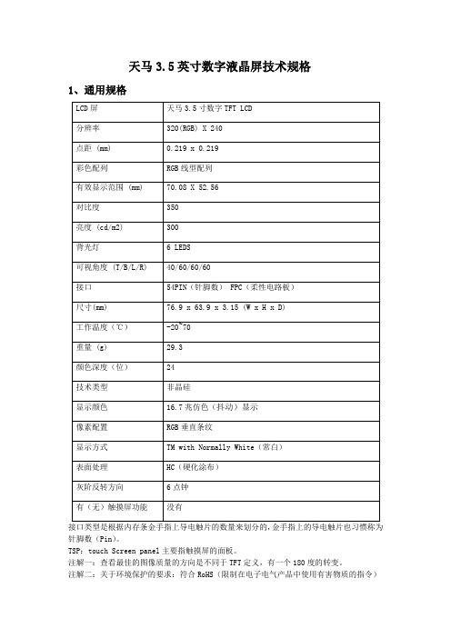
天马3.5英寸数字液晶屏技术规格1、通用规格接口类型是根据内存条金手指上导电触片的数量来划分的,金手指上的导电触片也习惯称为针脚数(Pin)。
TSP:touch Screen panel主要指触摸屏的面板。
注解一:查看最佳的图像质量的方向是不同于TFT定义,有一个180度的转变。
注解二:关于环境保护的要求:符合RoHS(限制在电子电气产品中使用有害物质的指令)注解三:LCM重量公差:±5%AS13LCM35D驱动板技术规格AS13LCM35D工作原理图图中名词解释Decoder:解码器,译码器VR(voltage regulation):电压调节(调压)MCU(Microprogrammed Control Unit):微程序控制器AS13LCM35D接口定义J3插座定义AS13LCM35D连接线示意图3、绝对最大额定参数(Absolute Maximum Ratings)3.1操作TFT-LCD面板(Driving TFT LCD Panel)4、电特性(Electrical Characteristics)4.1操作TFT-LCD面板(Driving TFT LCD Panel)GND=0V,Ta=25℃4.2控制背光(Driving Backlight)注解一:下图显示的LED背光连接。
注解二:一个LED:IF=20毫安,VF= 3.2V注解三:最小的LED寿命:20,000小时6、光学特性(Optical Characteristics)6.1光学鉴定(Optical Specification)Ta=25℃实验条件(Test Conditions)1. VF= 3.2V,IF = 20mA下的LED电流,环境温度为25℃。
2. 测试系统是指注解1和注解2。
注解一:光学测量系统的定义。
在黑暗的房间,应测量的光学特性。
运行5分钟后,测量的光学性质在液晶屏幕的中心点。
所有输入端子的液晶面板必须是地面测量时面板的中心区域。
Riverdi 3.5英寸 TFT 显示屏参考手册说明书

ITEMCONTENTSUNITLCD Type TFT/Transmissive/Normally white / Size3.5Inch Viewing Direction12:00 (without image inversion) O’ Clock Gray Scale Inversion Direction 6:00O’ Clock Number of Dots 320 x (RGB) × 240 / Driver ICBT81x / Interface TypeSPI/QSPI/ Module Memory Size 1 MB (BT81x) + 64 Mb (external flash) / Color Depth16.7M/ Pixel Arrangement RGB Vertical Stripe/ Surface Treatment Anti-glare / Clear (for CTP) / Input Voltage3.3V3.5” EVE3 SERIES LCD TFTRiTFT-35 seriesRev.1.0 2018-10-22L C D T F T M o d u l e S p e c i f i c a t i o nNote 1: RoHS, REACH SVHC compliant Note 2: LCM weight tolerance: ± 5%.CONTENTS (2)1 MODULE CLASSIFICATION INFORMATION (3)2 ASSEMBLY GUIDE - INTEGRATION (3)2.1 Mounting frame (4)3 MODULE DRAWING (4)4 ABSOLUTE MAXIMUM RATINGS (5)5 ELECTRICAL CHARACTERISTICS (5)6 BACKLIGHT CHARACTERISTICS (5)7 ELECTRO-OPTICAL CHARACTERISTICS (5)8 INTERFACE DESCRIPTION (7)9 BT8x CONTROLLER SPECIFICATIONS (8)9.1 Serial host interface (8)9.2 Block Diagram (8)9.3 Host interface SPI mode 0 (9)9.4 Backlight driver block diagram (9)10 LCD TIMING CHARACTERISTICS (9)10.1 Clock and data input time diagram (9)10.2 Parallel RGB timing table (11)11 TOUCH SCREEN PANEL SPECIFICATIONS (11)11.1 Electrical characteristics (11)11.1.1 For capacitive touch panel (11)11.1.2 For resistive touch panel (12)11.2 Mechanical characteristics (12)11.2.1 For capacitive touch panel (12)11.2.2 For resistive touch panel (13)12 INSPECTION (13)12.1 Inspection condition (13)12.2 Inspection standard (14)13 RELIABILITY TEST (17)14 LEGAL INFORMATION (18)1. BRAND RV – Riverdi2. PRODUCT TYPE T – TFT StandardF – TFT Custom3. DISPLAY SIZE 35– 3.5”4. MODEL SERIAL NO. A (A-Z)5. RESOLUTION H– 320x240 px6. INTERFACE B – TFT + Controller BT81x7. FRAME N – No FrameF – Mounting Frame8. BACKLIGHT TYPE W – LED White9. TOUCH PANEL N – No Touch PanelR – Resistive Touch Panel C – Capacitive Touch Panel10. VERSION 00(00-99)RiTFT-35-RES RVT35AHBNWR00 BT816, resistive touch panelRiTFT-35-CAP RVT35AHBNWC00 BT815, capacitive touch panelRiTFT-35-FR RVT35AHBFWN00 BT816, no touch panel, mounting frame RiTFT-35-RES-FR RVT35AHBFWR00 BT816, resistive touch panel, mounting frame RiTFT-35-CAP-FR RVT35AHBFWC00 BT815, capacitive touch panel, mounting frame2.1Mounting frameFor dimension s 3.5”, 4.3”, 5.0” and 7.0” the product with mounting frame version is available. Thanks to the four catches attached to the side, frame provides strong assembly to the surface by mounting element (like the screw, see Figure 3). The frames are specially designed to fit Riverdi products perfectly. The diameter of the mounting hole is 3.5mm.Figure 1. Mounting frameRiTFT-35 series3MODULE DRAWING `` RiTFT-35© 2018 Riverdi Page 4 of 24 RiTFT-35 seriesRiTFT-35-FR© 2018 Riverdi Page 5 of 24 RiTFT-35 seriesRiTFT-35-CAP© 2018 Riverdi Page 6 of 24 RiTFT-35-CAP-FR© 2018 Riverdi Page 7 of 24 RiTFT-35-RES© 2018 Riverdi Page 8 of 24 RiTFT-35-RES-FR© 2018 Riverdi Page 9 of 24 4ABSOLUTE MAXIMUM RATINGSPARAMETER SYMBOL MIN MAX UNITSupply Voltage for Logic VDD 0 4.0 V Supply Voltage for LED Inverter BLVDD 0 7.0 VInput Voltage for Logic VIN 0 4.0 VLED forward current (each LED) IF - 25 mA Operating Temperature T OP-20 70 °C PARAMETER SYMBOL MIN TYP MAX UNIT NOTES Supply Voltage For Module VDD 3.0 3.3 3.6 VInput Voltage for LED Inverter BLVDD 2.8 5.0 5.5 VLED Backlight Current IDD backlight- 150 187 mA BLVDD=3.3V LED Backlight Current IDD backlight- 93 117 mA BLVDD=5V Input Voltage ' H ' level V IH0.7VDD - VDD VInput Voltage ' L ' level V IL0 - 0.2VDD VInput Current I In TBD mAInput Current for module with CTP I InC TBD mAITEM SYMBOL MIN TYP MAX UNIT Voltage for LED backlight V l- 19.2 20.4 V Current for LED backlight I l- 20 25 mA LED Life Time - 30000 50000 - HrsLNote 1. Contrast Ratio(CR) is defined mathematically as below, for more information see Figure .Contrast Ratio =Average Surface Luminance with all white pixels (P1,P2,P3,P4,P5) Average Surface Luminance with all black pixels (P1,P2,P3,P4,P5)Note 2. Surface luminance is the LCD surface from the surface with all pixels displaying white. For more information, see Figure .Lv = Average Surface Luminance with all white pixels (P1, P2, P3, P4, P5)Note 3.The uniformity in surface luminance δ WHITE is determined by measuring luminance at each test position 1 through 5, and then dividing the maximum luminance of 5 points luminance by minimum luminance of 5 points luminance. For more information, see Figure .δ WHITE =Minimum Surface Luminance with all white pixels (P1,P2,P3,P4,P5) Maximum Surface Luminance with all white pixels (P1,P2,P3,P4,P5)Note 4. Response time is the time required for the display to transition from white to black (Rise Time, Tr) and from black to white (Decay Time, Tf). For additional information see FIG 1. The test equipment is Autronic-Melchers’s ConoScope series.Note 5.CIE (x, y) chromaticity, the x, y value is determined by measuring luminance at each test position 1 through 5, and then make average value.Note 6. Viewing angle is the angle at which the contrast ratio is greater than 2. For TFT module the contrast ratio is greater than 10. The angles are determined for the horizontal or x axis and the vertical or y axis with respect to the z axis which is normal to the LCD surface. For more information see Figure .Note 7. For viewing angle and response time testing, the testing data is based on Autronic-Melchers’s ConoScope series. Instruments for Contrast Ratio, Surface Luminance, Luminance Uniformity, CIE the test data is based on TOPCON’s BM-5 photo detector.Note 8. For TFT module, Gray scale reverse occurs in the direction of panel viewing angle.Figure 2. The definition of response timeFigure 3. Measuring method for Contrast ratio, surface luminance, Luminance uniformity, CIE (x, y) chromaticityFigure 4.The definition of viewing angle8INTERFACE DESCRIPTION9BT8x CONTROLLER SPECIFICATIONSBT8x or EVE3 (Embedded Video Engine 3) simplifies the system architecture for advanced human machine interfaces (HMIs) by providing functionality for display, audio, and touch as well as an object oriented architecture approach that extends from display creation to the rendering of the graphics.9.1Serial host interfaceFigure 5.SPI interface connection Figure 6. QSPI interface connectionSPI Interface– the SPI slave interface operates up to 30MHz.Only SPI mode 0 is supported. The SPI interface is selected by default (MODE pin is internally pulled low by 47k resistor).9.2Block DiagramFigure 7.. BT8x Block diagram9.3Host interface SPI mode 0Figure 8. SPI timing diagramFor more information about BT8x controller please go to official BT8x website.https:///Products/ICs/BT81X.html9.4Backlight driver block diagramBacklight enable signal is internally connected to BT8x Backlight control pin. This pin is controlled by two BT8x’s registers. One of them specifies the PWM output frequency, second one specifies the duty cycle. Refer to BT8x datasheet for more information.Figure 9. Backlight driver block diagram10LCD TIMING CHARACTERISTICS10.1Clock and data input time diagramFigure 10. DE mode timing diagramBT8xFigure 11. SYNC mode timing diagramFigure 12. Timing diagram10.2Parallel RGB timing tableTiming parameter (VDD=3.3V, GND=0V, Ta=25˚C)PARAMETER SYMBOL MIN TYP MAX UNIT CONDITION CLK Clock Time T clk 1/Max(F CLK) - 1/Min(F CLK) ns -11TOUCH SCREEN PANEL SPECIFICATIONS11.1Electrical characteristicsNote: Avoid operating with hard or sharp material such as a ball point pen or a mechanical pencil except a polyacetal pen (tip R0.8mm or less) or a fingerITEM VALUE UNIT REMARKMin. Typ. Max.Linearity - - 1.5 % Analog X and Y directions Terminal Resistance 200 - 900 ΩX100 - 600 ΩY11.2Mechanical characteristicsNote 1: Force test condition, Input DC 5V on X direction, Drop off Polyacetal Stylus (R0.8), until output voltage stabilize, then get the R8.0mm Silicon rubber and do finger Activation force test. Next step, 9 points.Note 2: Measurement surface area conditions, Scratch 100,000 times straight line on the film with a stylus change every 20,000 times with Force: 250gf, Speed: 60mm/sec by R0.8 polaceteal stylus.Note 3: Pitting test, Pit 1, 000, 000 times on the film with R0.8 silicon rubber with Force: 250gf and Speed: 2 times/sec.Note 1: Force test condition, Input DC 5V on X direction, drop off Polyacetal Stylus (R0.8), until output voltage stabilize, then get the R8.0mm Silicon rubber and do finger Activation force test. Next step, 9 points.ITEM VALUE UNIT REMARKMin. Typ. Max.12INSPECTIONStandard acceptance/rejection criteria for TFT module.12.1Inspection conditionAmbient conditions:•Temperature: 25±°C•Humidity: (60±10) %RH•Illumination: Single fluorescent lamp non-directive (300 to 700 lux)Viewing distance:35±5cm between inspector bare eye and LCD.Viewing Angle:U/D: 45°/45°, L/R 45°/45°12.2Inspection standard Item Criterion Black spots, whitespots, light leakage,Foreign Particle(round Type)D=(x+y)2*Spots density: 10 mmSize < 5”Average Diameter Qualified QtyD < 0.2 mm Ignored0.2 mm < D < 0.3 mm 30.3 mm < D < 0.5 mm 20.5 mm < D 0Size >= 5”Average Diameter Qualified Qty D<0.2 mm Ignored0.2 mm < D < 0.3 mm 40.3 mm < D < 0.5 mm 20.5 mm < D 0Clear spotsSize >= 5”Average Diameter Qualified Qty D<0.2 mmIgnored 0.2 mm < D < 0.3 mm 4 0.3 mm < D < 0.5 mm 2 0.5 mm < D*Spots density: 10 mm Size < 5”Average Diameter Qualified Qty D < 0.2 mmIgnored 0.2 mm < D < 0.3 mm 3 0.3 mm < D < 0.5 mm 2 0.5 mm < D 0Polarizer bubblesSize < 5”Average Diameter Qualified Qty D < 0.2 mmIgnored 0.2 mm < D < 0.5 mm 3 0.5 mm < D < 1 mm 2 1 mm < D 0 Total Q’ty 3Size >= 5”Average Diameter Qualified Qty D<0.25 mmIgnored 0.25 mm < D < 0.5 mm 3 0.5 mm < D 0Electrical Dot DefectSize < 5”itemQualified Qty Black do defect 4 Bright dot defect 2 Total Dot 5Size >= 5”itemQualified Qty Black do defect 5 Bright dot defect 2 Total Dot 5Touch panel spotSize < 5”Average Diameter Qualified QtyD < 0.2 mm Ignored0.2 mm < D < 0.4 mm 50.4 mm < D < 0.5 mm 213RELIABILITY TESTNO. TEST ITEM TEST CONDITION REMARKS1 High Temperature Storage 80±2°C/240hours Note 22 Low Temperature Storage -30±2°C/240hours Note 1,2Note 1: Without water condensation.Note 2:The function test shall be conducted after 2 hours storage at the room temperature and humidity after removed from the test chamber.14LEGAL INFORMATIONRiverdi makes no warranty, either expressed or implied with respect to any product, and specifically disclaims all other warranties, including, without limitation, warranties for merchantability, non-infringement and fitness for any particular purpose. Information about device are the property of Riverdi and may be the subject of patents pending or granted. It is not allowed to copy or disclosed this document without prior written permission.Riverdi endeavors to ensure that the all contained information in this document are correct but does not accept liability for any error or omission. Riverdi products are in developing process and published information may be not up to date. Riverdi reserves the right to update and makes changes to Specifications or written material without prior notice at any time. It is important to check the current position with Riverdi.Images and graphics used in this document are only for illustrative the purpose. All images and graphics are possible to be displayed on the range products of Riverdi, however the quality may vary. Riverdi is no liable to the buyer or to any third part for any indirect, incidental, special, consequential, punitive or exemplary damages (including without limitation lost profits, lost savings, or loss of business opportunity) relating to any product, service provided or to be provided by Riverdi, or the use or inability to use the same, even if Riverdi has been advised of the possibility of such damages.Riverdi products are not fault tolerant nor designed, manufactured or intended for use or resale as on line control equipment in hazardous environments requiring fail – safe performance, such as in the operation of nuclear facilities, aircraft navigation or communication systems, air traffic control, direct life support machines or weapons systems in which the failure of the product could lead directly to death, personal injury or severe physical or environmental damage (‘High Risk Activities’). Riverdi and its suppliers specifically disclaim any expressed or implied warranty of fitness for High Risk Activities. Using Riverdi products and devices in 'High Risk Activities' and in any other application is entirely at the buyer’s risk, and the buyer agrees to defend, indemnify and hold harmless Riverdi from any and all damages, claims or expenses resulting from such use. No licenses are conveyed, implicitly or otherwise, under any Riverdi intellectual property rights.。
vcvd_a
Page5
E. 外观
z 板尺寸: 115.0mm*90.2mm z 厚度: <12mm,包括板的厚度和所有的元件。
z 产品图片:
Page6
F. 各连接器件的定义:
连接器件名称 连接器件定义 脚名称
1
A
电源
2
3
4
1
2
3
4
5
B
VGA 信号输入 6
7
8
9
10
11
12
1
2
3
C
视频信号输入 4
5
6
7
8
1
2
Page9
40
GND
Power ground
41
DCLK
Sample clock
42
VCC
Voltage for digital circuit
43
STHR
Horizontal start pulse input when R/L = L
44
LD
Latches the polarity of outputs and switches
中华:5.7寸 (CLAA057VA01CW_V0) ---单40pin 中华:7寸(CLAA070VA01)---单40pin 中华:8寸(CLAA080MB0DCW)---双30pin
翰彩:7寸(HSD070IDW1)---单60pin 翰彩:8寸(HSD080IDW1)---单60pin 翰彩: 10寸(HSD100IXN1) --- 双30pin(1024*768) 翰彩: 10寸(HSD100IFW1-C00) --- 双30pin(1024*600)
the new data to outputs
产品安装说明书

1.0 安装说明1.1 安装指南1.1.1 安装位置注意在安装配套设备时,请确保交流电源线、PLC、电磁阀、启动器、继电器或其它类型的电气接口设备与本产品保持适当距离,避免不同设备之间产生电磁干扰。
需特别注意安装变频器、伺服驱动器和开关电源等强干扰源设备时与本产品保持较远距离,此类设备的输入和输出线请务必采用屏蔽电缆线,并将屏蔽网接到系统的星形接地点。
1.1.2 环境注意事项1.2.1 电源要求1.1.3 应用环境本公司产品是依据工业应用环境而设计,设计的应用环境温度能够在-10℃~50℃的大多数工业环境中稳定工作,可能不适用于某些特别的室外环境,请使用者慎重选择!1.1.4 电气环境本公司产品已经通过测试符合欧盟CE电气认证的标准,即产品的电路设计可以抵抗电气噪声的干扰,但并不保证适应所有情况的电气噪声干扰,请使用者正确的布线和接地以确保正确使用。
1.2 电源连接在安装本产品前请确认符合所在区域或国家的电气标准,详情请向厂家咨询。
显示尺寸整机尺寸有效显示区尺寸3.5英寸102.5*60*17mm73.44*48.96mm液晶屏尺寸85.5*55*4mm螺丝孔间距96*40mm显示尺寸整机尺寸开孔尺寸3.5英寸115*71*25mm107*65mm有效显示区尺寸73.44*48.96mm建议开孔尺寸109*67mm系列 安装说明书AST 正面背面左侧面右侧面4.5 AST035串口屏通讯接口针脚定义(三选一):底面5.1 AST035触摸屏正面通讯接口针脚定义(三选一):5.0 触摸屏系列请前往本公司官网下载编程软件,注意匹配编辑软件版本:《HMILite_Setup_V2.1组态软件》。
2.0 编程软件显示尺寸整机尺寸有效显示区尺寸2.4英寸78.5*48.5*17mm48.96*36.72mm液晶屏尺寸60.5*42.5*4mm螺丝孔间距68.5*36.5mm显示尺寸整机尺寸有效显示区尺寸2.8英寸86.5*55.5*17mm57.6*43.2mm液晶屏尺寸69*50*4mm螺丝孔间距78*46.5mm显示尺寸整机尺寸有效显示区尺寸2.4英寸78.5*48.5*12mm48.96*36.72mm液晶屏尺寸60.5*42.5*4mm螺丝孔间距68.5*36.5mm显示尺寸整机尺寸有效显示区尺寸2.8英寸86.5*55.5*12mm57.6*43.2mm液晶屏尺寸69*50*4mm螺丝孔间距78*46.5mm4.1 AST024串口屏背面左侧面右侧面3.0 型号定义AST K 028NGD通信类型:D表示串口1为485通信,E表示串口1为232通信,T表示串口1为TTL通信外壳颜色: G表示外壳颜色为灰色触摸类型: N表示不带TP ,R表示带TP 屏尺寸: 表示产品型号尺寸 2.8寸K:表示带按键,E表示经济款屏系列:表示串口屏系列ASTE024/028 通讯接口针脚定义:4.4 ASTE028串口屏4.2 AST028串口屏AST024/028 通讯接口针脚定义(三选一):4.0 串口屏系列。
3.5英寸HDMI LCD 产品说明书
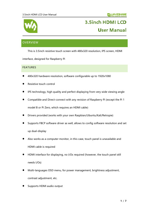
3.5inch HDMI LCDUser Manual OVERVIEWThis is 3.5inch resistive touch screen with 480x320 resolution, IPS screen, HDMI interface, designed for Raspberry PiFEATURES⚫480x320 hardware resolution, software configurable up to 1920x1080⚫Resistive touch control⚫IPS technology, high quality and perfect displaying from very wide viewing angle ⚫Compatible and Direct-connect with any revision of Raspberry Pi (except the Pi 1 model B or Pi Zero, which requires an HDMI cable)⚫Drivers provided (works with your own Raspbian/Ubuntu/Kali/Retropie)⚫Supports FBCP software driver as well, allows to config software resolution and set up dual-display⚫Also works as a computer monitor, in this case, touch panel is unavailable and HDMI cable is required⚫HDMI interface for displaying, no I/Os required (however, the touch panel still needs I/Os)⚫Multi-languages OSD menu, for power management, brightness adjustment, contrast adjustment, etc.⚫Supports HDMI audio outputOverview (1)Features (1)How to use (3)Hardware connection (3)Method 1, Install driver (3)Method 2 Using ready-to-use image (4)Software configuring resolution (4)Setting orientation (5)Calibration (6)The touch of the LCD can be driven in two ways: Method 1: Install driver manually; Method 2: Using ready-to-use ImageHARDWARE CONNECTION⚫Insert LCD directly to 40PIN header of Raspberry Pi.⚫Using the HDMI adapter or HDMI cable to connect HDMI interface of LCD to Raspberry Pi’sMETHOD 1, INSTALL DRIVER1.Download lasted OS1image from Raspberry Pi website.2.Extract image from ZIP archive and write it to SD card3.After writing, modify the config.txt file which is located at root directory (BOOT) ofSD card. Append these statements to the end of config.txt file1This instruction is based on Raspbian OS4.Insert SD card to Raspberry Pi and power it on.5.Connect to network,open terminal to download and install driver.6.Waiting for rebootingMETHOD 2 USING READY-TO-USE IMAGE1.Download image we provided on wiki- Raspbian for 3.5inch HDMI LCD2.Extract the image file and write to SD card3.Insert the SD card to Raspberry Pi and power on.SOFTWARE CONFIGURING RESOLUTIONThe hardware resolution of 3.5inch HDMI LCD, it can also support software configuring resolution. As we test in Raspbian with Raspberry Pi, the LCD supports 480×320 800×480 800×600 1024×768 1152×864 1280×720 1280×768 1280×8001280×960 1280×1024 1360×768 1366×768 1440×900 1600×900 1600×1024 1680×1050.To configure the resolution, you can modify the config.txtChange the parameters of hdmi_cvt, for example, change to 800x480Save and reboot.【Note】Because the LCD is only 3.5inch, we recommend you to use 480x320 or 800x480 resolution setting.SETTING ORIENTATIONAfter installing driver, you can set the orientation as below【Note】X can be 0, 90, 180 or 270CALIBRATIONIf the touch of RPi LCD is not calibrated, you can calibrate the touch screen.1.Copy and install calibrator tool2.Install X service3.Running calibrator and finish calibration4.Saving the calibration data to 99-clibration.conf fileT he calibration data looks like;。
3.5寸TFT液晶规格书
Contents TFT transmissive, Normally white 6 O’clock 54.66(W)X82.94(H)X2.3(T) 48.96(W) x 73.44(H) 320(H) x (R.G.B.) x480(W) HX8357B 262K LED NC 8080 system 8/16 bit parallel T.B.D.
TEL: 86-0755-23000930 FAX : 86-0755-23000936
Doc No: Rev.:
XC-T0353701 0 2012.03.26
6 of 23
深圳信创光电技术有限公司
SHEN ZHEN SHI SINGSTART OPTOELECTRONIC CO., .,LTD .,
Item Contrast ratio (Center point) Response Rising: Tr Time Falling:Tf White Color Chromaticit y (CIE 1931) Red Green Blue Hor Ver
Symbol C/R Tr Tf Wx Wy Rx Ry Gx Gy Bx By θL1 θR1 øU1 øD1
Min -0.3 -0.3 -10 -20 -
Max 3.3 Vcc+0.3 60 70 90%(Max60°C) 15
Unit V V °C °C Dot mA(each Led)
Doc No: Rev.:
XC-T0353701 0 2012.03.26
8 of 23
深圳信创光电技术有限公司
SHEN ZHEN SHI SINGSTART OPTOELECTRONIC CO., .,LTD .,
YDSTECH PCM-9351 3.5寸嵌入式主板 说明书
用 户 手 册第2. 3版2011年7月发行w w w.y d s t e c h.c o m前言感谢您购买英德斯科技公司PCM-9351主板,该主板采用英特尔凌动低功耗芯片组设计。
板载Intel® Atom™ Processor N450/D510/D525可选处理器。
板载DDR2-667 1G内存。
芯片组集成了高效能图形加速卡,支持动态显存分配技术,能够提供强大的图像处理能力。
采用Realtek ALC662音效芯片满足客户对高品质音效的享用。
另外Realtek 8111D 网络芯片可带您进入千兆高速以太网网络环境,并随时听命于您的使唤,使远程控制变得更加简单。
而板载看门狗功能使您的设备变得更加智能,控制更加方便。
PCM-9351支持ATX电源管理方案,采用了最为成熟的电源设计方案(宽压供电9~36V ),保证了CPU在高速运算时的稳定性。
高效的散热器则很好地提升了显示芯片和附近芯片的稳定性。
该板采用8层PCB板设计,单独的电源层和地层降低了电源信号间的干扰,同时各I/O端口都进行了专门的EMC设计处理,这些周到的设计使得PCM-9351获得更为稳定的整体性能。
除此之外PCM-9351还具有运算速度快、图形处理能力强劲、数据传输速度快和优秀的稳定性设计,适合于图形运算量大、数据存储速度快和全天候工作的场合,可广泛应用于监控、安防、工厂控制、金融和智能交通等领域;9~36V宽压供电尤其适合于车载系统解决方案。
目录版权声明 (4)商标 (4)技术支持 (4)获得更多的产品信息 (4)关于本手册 (4)安装前注意事项 (4)配件清单 (5)第一章主机板规格简介 (6)第二章硬件安装与设置 (7)2.1主板正面位置图... . (7)2.2主板背面位置图 (8)2.3主板尺寸图 (9)2.4主板跳线 ....................................................... .102.5主板接口 (10)2.6如何识别跳线的第一脚 (11)2.7跳线的设置 (11)2.8 清空CMOS (11)2.9 CF卡主从选择 (12)2.10 COM2工作方式选择 (12)2.11 TTL/LVDS电压选择 (12)2.12硬盘供电接口 (12)2.13 前面板接口 (13)2.14LVDS接口 (13)2.15GPIO接口 (13)2.16一分四USB接口 (14)2.17音频接口 (14)2.18PS/2接口 (14)2.19打印机接口 (14)2.20一分四串口 (15)2.21COM6接口 (16)2.22红外接口 (16)2.23 IDE接口 (17)2.24 PC104+接口 (18)第三章外部设备的安装 (21)第四章驱动程序安装 (21)附录 (22)watchdog编程实例...................................................... .22 GPIO编程实例.......................................................... .22 联系英德斯公司 (23)版权声明本手册版权属于深圳市英德斯电子有限公司所有,未经本公司许可,不得任意地仿制、拷贝、摘抄或转译。
【液晶屏LVDS接口详解】:教你将闲置的液晶屏利用起来
【液晶屏LVDS接口详解】:教你将闲置的液晶屏利用起来1、液晶屏先说液晶屏,只要不是太特殊的笔记本,绝大多数都是LVDS接口的,极少是TTL 的,这个看液晶屏的针脚可以大致判断出来(注意是看液晶屏上的接口,不是已经引出的屏线),LVDS的一般是14、20、30针,TTL的多是31、41针。
如果是LVDS接口的,恭喜你,这个屏可以利用起来的概率极大,本文仅针对LVDS 讲解。
再看看液晶屏的分辨率,早期笔记本多数是4:3的,物理分辨率为800*600或1024*768,这个分辨率是很容易驱动的;新一点的16:9、16:10的宽屏液晶要利用起来要麻烦些,需要找到合适的驱动板。
下面是我驱动起来的几个液晶屏这个是最开始买的一个8.9寸的宽屏,用做客厅HTPC的副显示。
分辨率是1024*600,最开始没有配到合适的驱动板,前年才找到个完美点对点的驱动板。
开始配了个VGA\AV双路输入的驱动板,这个是AV信号这个是富士通触摸笔记本拆出来的12寸屏幕,有两块,一块是800*600,一块是1024*768,也做了个一体电控:一体电控的帖子:刚驱动起来的样子这个是现在做的雕刻机用的屏幕,清华同方的笔记本拆出来的,分辨率是1024*7682013-3-23 22:08 上传下载附件 (85.94 KB)这个是唯一一块没驱动起来的笔记本液晶屏,是SHARP笔记本拆出来的,屏也是SHARP的,800*600,5V的。
2、驱动板要使液晶屏能显示,需要接入LVDS信号,这有两个来源:一是常规的,将VGA信号转为LVDS信号连接液晶屏、二是工控主板上常常集成了LVDS接口,只要将对应针脚连接起来即可。
需要注意的是,不同分辨率的液晶屏,需要在驱动板中写入相应的程序,否则不能正常显示,这个可以在买液晶驱动板的时候给商家说明,现在也有一些通过跳线选择分辨率的驱动板,如果再烧点,就买个液晶烧录器自己玩;而工控主板常常是在BIOS里设置LVDS输出的分辨率。
友达光电 (AUO) 31.5 英寸 T315XW02_VT_v0 液晶电视屏规格书
January, 2008 All Rights Reserved. T315XW02 VT - Specs. Ver 0.5 1/31No Reproduction and Redistribution AllowedDocument Version : 0.5Date : 2009/06/03Product Specifications31.5” WXGA Color TFT-LCD ModuleModel Name: T315XW02 VT( ) Preliminary Specifications(*) Final Specifications ©Copyright AU Optronics, Inc.January, 2008 All Rights Reserved. T315XW02 VT - Specs. ver 0.5 2/31No Reproduction and Redistribution Allowed©Copyright AU Optronics, Inc.January, 2008 All Rights Reserved. T315XW02 VT - Specs. ver 0.5 3/31No Reproduction and Redistribution AllowedContentsINTERFACE CONNECTIONS 3-2 COLOR INPUT DATA REFERNECE 3-5 PRECAUTIONS9PACKING 8 EMC 7-2COVER CONTENTSRECORD OF REVISIONS GENERAL DESCRIPTION 1 ABSOLUTE MAXIMUM RATINGS 2 ELECTRICAL SPECIFICATIONS 3 ELECTRICAL CHARACTREISTICS 3-1 SIGNAL TIMING SPECIFICATIONS 3-3 SIGNAL TIMING WAVEFORMS 3-4 POWER SEQUENCE 3-6 OPTICAL SPECIFICATIONS 4 MECHANICAL CHARACTERISTICS 5 RELIABLITY6 INTERNATIONAL STANDARDS7 SAFETY 7-1No©Copyright AU Optronics, Inc.January, 2008 All Rights Reserved. T315XW02 VT - Specs. ver 0.5 4/31No Reproduction and Redistribution AllowedRecord of RevisionVersionDateNoOld DescriptionNew Description Remark0 2008/10/31 First issue2008/12/3112Inverter pin assignment: Pin11=Panel status d etect. (Normal=0-0.8V . Abnormal=Open collec tor)Inverter pin assignment: Pin11=AUO internal use. Keep Open. update11 input power typ=75W Input power typ=78Wupdate 17Update power sequence of inverter update 0.1 2009/02/048 4. VCIM=1.2V 4. VCIM=1.25Vupdate11Input Power (Turn on Condition) Input Current (Turn on Condition) update7 4. Measurement condition Trush=400uS 4. Measurement condition Trush=470uS update 23 Gap= 0.66 Gap= 0.66 (1.2 Max)update 0.2 2009/2/2325 Safety: (4) EN60065: 2002; IEC 60065: 2001 add 26Update shipping label and carton label format update 18 Brightness typ: 400nit Brightness typ: 420nit update 0.3 2009/02/27 22Update front view drawing update 0.4 2009/3/12 21 Bezel Open vertical=398.3mm Bezel Open vertical=398.4mm update 0.5 2009/06/0326Add Taiwan module fabadd 12 Inverter pin assignment: Pin11=AUO internal use. Keep Open. Inverter pin assignment: Pin11=Panel status d etect. (Normal=0-0.8V . Abnormal=Open collector) update©Copyright AU Optronics, Inc.January, 2008 All Rights Reserved. T315XW02 VT - Specs. ver 0.5 5/31No Reproduction and Redistribution Allowed1. General DescriptionThis specification applies to the 31.51 inch Color TFT-LCD Module T315XW02 VT. This LCD module has a TFT active matrix type liquid crystal panel 1366x768 pixels, and diagonal size of 31.51 inch. This module supports 1366x768 XGA-WIDE mode (Non-interlace).Each pixel is divided into Red, Green and Blue sub-pixels or dots which are arranged in vertical stripes. Gray scale or the brightness of the sub-pixel color is determined with a 8-bit gray scale signal for each dot.The T315XW02 VT has been designed to apply the 8-bit 1 channel LVDS interface method. It is intended to support displays where high brightness, wide viewing angle, high color saturation, and high color depth are very important.The T315XW02 VT model is RoHS verified which can be distinguished on panel label.* General InformationItemsSpecificationUnitNoteActive Screen Size 31.51 inches Display Area 697.685 (H) x 392.256(V) mm Outline Dimension 760.0(H) x 450.0(V) x 45(D) mm Driver Element a-Si TFT active matrixDisplay Colors 16.7M Colors Number of Pixels 1366 x 768 Pixel Pixel Pitch 0.51075 mm Pixel Arrangement RGB vertical stripe Display Mode Normally BlackSurface TreatmentAnti-Glare, 3HHaze =11%©Copyright AU Optronics, Inc.January, 2008 All Rights Reserved. T315XW02 VT - Specs. ver 0.5 6/31No Reproduction and Redistribution Allowed2. Absolute Maximum RatingsThe following are maximum values which, if exceeded, may cause permanent damage to the unit.ItemSymbol Min Max UnitConditions Logic/LCD Drive Voltage Vcc -0.3 14 [Volt] Note 1 Input Voltage of Signal Vin -0.3 3.6 [Volt] Note 1 BLU Input VoltageVDDB -0.3 28 [Volt] Note 1 BLU Brightness Control Voltage Vdim -0.3 7.0 [Volt] Note 1 Operating Temperature TOP 0 +50 [o C] Note 2 Operating Humidity HOP 10 90 [%RH] Note 2 Storage Temperature TST -20 +60 [o C] Note 2 Storage Humidity HST 10 90 [%RH] Note 2 Panel Surface Temperature PST65[o C]Note 3Note 1: Duration:50 msec.Note 2 : Maximum Wet-Bulb should be 39 and No condensation.℃The relative humidity must not exceed 90% non-condensing at temperatures of 40 or less. At tem ℃peratures greater than 40, the wet bulb temperature must not exceed 39. ℃℃ Note 3 : Surface temperature is measured at 50℃ Dry condition©Copyright AU Optronics, Inc.January, 2008 All Rights Reserved. T315XW02 VT - Specs. ver 0.5 7/31No Reproduction and Redistribution Allowed3. Electrical SpecificationThe T315XW02 VT requires two power inputs. One is employed to power the LCD electronics and to drive the TFT array and liquid crystal. The second input power for the BLU, is to power inverter.3-1 Electrical CharacteristicsValuesParameterSymbolMinTypMaxUnit NotesLCD:Power Supply Input V oltage Vcc 10.8 12 13.2 Vdc 1 Power Supply Input Current Icc - 0.45 0.55 A 2 Power Consumption Pc - 5.4 7.26 Watt 2 Inrush CurrentI RUSH - - 6 Apeak 3 Differential Input High ThresholdV oltageVTH-- 100 mV4Differential Input Low Threshold V oltageVTL -100 - - mV 4LVDSInterface Common Input V oltageVCIM 1.10 1.25 1.40 V 4 Input High Threshold Voltage VIH (High)2.43.3VdcCMOS InterfaceInput Low Threshold V oltageVIL (Low)0 0.7 VdcLife Time 50,000 Hours 5,6,7,8Note :1. The ripple voltage should be controlled under 10% of V CC2. Vcc=12.0V ,=v f 60Hz, fCLK=81.5Mhz , 25, Test Pattern : White Pattern ℃3. Measurement condition :©Copyright AU Optronics, Inc.January, 2008 All Rights Reserved. T315XW02 VT - Specs. ver 0.5 8/31No Reproduction and Redistribution Allowed4. VCIM = 1.25V5. The performance of the Lamp in LCD panel, for example life time or brightness, is extremelyinfluenced by the characteristics of the DC-AC Inverter. So all the parameters of an inverter should be carefully designed as not to produce too much leakage current from high-voltage output of the inverter. When you design or order the inverter, please make sure unwanted lighting caused by the mismatch of the lamp and the inverter (no lighting, flicker, etc) never occurs. After confirmation, the LCD panel should be operated in the same condition as installed in your instrument.6. Do not attach a conducting tape to lamp connecting wire. If the lamp wire attach to conducting tape,TFT-LCD Module have a low luminance and the inverter has abnormal action because leakage current occurs between lamp wire and conducting tape.7. The relative humidity must not exceed 80% non-condensing at temperatures of 40 or less. At℃temperatures greater than 40, the wet bulb temperature must not exceed 39. When operate at ℃℃low temperatures, the brightness of CCFL will drop and the life time of CCFL will be reduced. 8. Specified values are for a single lamp only which is aligned horizontally. The lifetime is defined asthe time which luminance of the lamp is 50% compared to its original value. [Operating condition: Continuous operating at Ta = 25±2℃]0V©Copyright AU Optronics, Inc.January, 2008 All Rights Reserved. T315XW02 VT - Specs. ver 0.5 9/31No Reproduction and Redistribution Allowed3-2 Interface Connections-Connector on Panel: 093G30-B0001A-1 (Manufactured by Starconn ) Pin NoSymbolDescriptionDefault1 VCC +12V , DC, Regulated2 VCC +12V , DC, Regulated3 VCC +12V , DC, Regulated4 VCC +12V , DC, Regulated5 GND Ground and Signal Return6 GND Ground and Signal Return7 GND Ground and Signal Return8 GNDGround and Signal Return9 LVDS Option Low/Open for Normal (NS), High for JEIDA NS mode 10 Reserved Open AUO internal test11 GND Ground and Signal Return for LVDS 12 RIN0- LVDS Channel 0 negative 13 RIN0+ LVDS Channel 0 positive14 GND Ground and Signal Return for LVDS 15 RIN1- LVDS Channel 1 negative 16 RIN1+ LVDS Channel 1 positive17 GND Ground and Signal Return for LVDS 18 RIN2- LVDS Channel 2 negative 19 RIN2+ LVDS Channel 2 positive20 GND Ground and Signal Return for LVDS 21 RCLK- LVDS Clock negative 22 RCLK+ LVDS Clock positive23 GND Ground and Signal Return for LVDS 24 RIN3- LVDS Channel 3 negative 25 RIN3+ LVDS Channel 3 positive26 GNDGround and Signal Return for LVDS27 Reserved Open or High AUO internal test 28 Reserved Open or High AUO internal test29 GND Ground and Signal Return 30GNDGround and Signal ReturnNote:1. All GND (ground) pins should be connected together and should also be connected to the LCD’smetal frame. All Vcc (power input) pins should be connected together.2. For Pin 10, 27 and 28, panel will not damage if negligently connect these pins to high or low©Copyright AU Optronics, Inc.January, 2008 All Rights Reserved. T315XW02 VT - Specs. ver 0.5 10/31No Reproduction and Redistribution AllowedLVDS Option = High (JEIDA)LVDS Option = Low or Open (NS)BACKLIGHT CONNECTOR PIN CONFIGURATION 1. Electrical specificationNote 1 : Measurement condition Rising time = 20 ms (VDDB : 10%~90%); Note 2 : VDIM= 3.3V (MAX, 100% brightness), VDIM= 0V (MIN, 10% brightness) Note 3 : (a) Uniformity and flicker does not guarantee under 20% dimming control. (b) 10% dimming function okay and no backlight shut down Ta=25±5 , Turn on for 45minutes©Copyright AU Optronics, Inc. January, 2008 All Rights Reserved. T315XW02 VT No Reproduction and Redistribution Allowed-Specs. Ver 0.511/31Buy It: )℃(2. Input specificationCN1: CI0114M1HRL-LF (Manufactured by Civilux)©Copyright AU Optronics, Inc. January, 2008 All Rights Reserved. T315XW02 VT No Reproduction and Redistribution Allowed-Specs. ver 0.512/31Buy It: 3-3 Signal Timing SpecificationsThis is the signal timing required at the input of the User connector. All of the interface signal timing should be satisfied with the following specifications for it’s proper operation. * Timing Table DE only Mode Vertical Frequency:Notes: 1.) Display position is specific by the rise of DE signal only. Horizontal display position is specified by the rising edge of 1st DCLK after the rise of 1st DE, is displayed on the left edge of the screen. Vertical display position is specified by the rise of DE after a “Low” level period equivalent to eight times of horizontal period. The 1st data corresponding to one horizontal line after the rise the of 1st DE is displayed at the top line of screen. 2.) The display position does not fit to the screen if a period of DE “High” and the effective data period do not synchronize with each other.©Copyright AU Optronics, Inc. January, 2008 All Rights Reserved. T315XW02 VT No Reproduction and Redistribution Allowed-Specs. ver 0.513/31Buy It: Tv Tdisp(v) ThRGB Data 768 Line Invalid Data1 Line2 Line3 Line4 Line768 LineInvalid DataCLK Th Tclk Tdisp(h)DERGB DataPixel 1366Invalid DataPixel 1Pixel 2Pixel 3Pixel 4Pixel 5Pixel 6Pixel 1366Invalid DataPixel 1Pixel 2©Copyright AU Optronics, Inc. January, 2008 All Rights Reserved. T315XW02 VT No Reproduction and Redistribution Allowed3-4 Signal Timing Waveforms-Specs. Ver 0.5DEBuy It: 14/313-5 Color Input Data ReferenceThe brightness of each primary color (red, green and blue) is based on the 8 bit gray scale data input for the color; the higher the binary input, the brighter the color. The table below provides a reference for color versus data input.COLORDATA REFERENCEInput Color DataColor MSBRED LSB MSBGREEN LSB MSBBLUE LSBR7 R6 R5 R4 R3 R2 R1 R0 G7 G6 G5 G4 G3 G2 G1 G0 B7 B6 B5 B4 B3 B2 B1 B0 Black Red(255) Green(255) Basic Color Blue(255) Cyan Magenta Yellow White RED(000) RED(001) RED ---RED(254) RED(255) 1 1 1 1 0 0 1 1 0 0 1 1 0 0 1 1 0 0 1 1 0 0 1 1 0 0 0 1 0 0 0 0 0 0 0 0 0 0 0 0 0 0 0 0 0 0 0 0 0 0 0 0 0 0 0 0 0 0 0 0 0 1 0 0 0 0 0 0 0 0 0 0 0 0 0 0 0 0 0 0 0 0 0 0 0 0 0 0 0 0 0 0 0 0 0 1 0 0 0 1 1 1 0 0 0 1 0 0 0 1 1 1 0 0 0 1 0 0 0 1 1 1 0 0 0 1 0 0 0 1 1 1 0 0 0 1 0 0 0 1 1 1 0 0 0 1 0 0 0 1 1 1 0 0 0 1 0 0 0 1 1 1 0 0 0 1 0 0 0 1 1 1 0 1 0 0 1 0 1 0 1 1 0 0 0 0 1 0 1 0 1 1 0 0 0 0 1 0 1 0 1 1 0 0 0 0 1 0 1 0 1 1 0 0 0 0 1 0 1 0 1 1 0 0 0 0 1 0 1 0 1 1 0 0 0 0 1 0 1 0 1 1 0 0 0 0 1 0 1 0 1 1 0 0 0 0 0 1 1 1 0 1 0 0 0 0 0 1 1 1 0 1 0 0 0 0 0 1 1 1 0 1 0 0 0 0 0 1 1 1 0 1 0 0 0 0 0 1 1 1 0 1 0 0 0 0 0 1 1 1 0 1 0 0 0 0 0 1 1 1 0 1 0 0 0 0 0 1 1 1 0 1 0 0GREEN(000) 0 GREEN(001) 0 GREEN ---GREEN(254) 0 GREEN(255) 0 BLUE(000) BLUE(001) BLUE ------BLUE(254) BLUE(255) 0 0 0 00 0 0 00 0 0 00 0 0 00 0 0 00 0 0 00 0 0 00 0 0 01 1 0 01 1 0 01 1 0 01 1 0 01 1 0 01 1 0 01 1 0 00 1 0 00 0 0 00 0 0 00 0 0 00 0 0 00 0 0 00 0 0 00 0 0 00 0 0 10 00 00 00 00 00 00 00 00 00 00 00 00 00 00 01 11 11 11 11 11 11 10 1©Copyright AU Optronics, Inc. January, 2008 All Rights Reserved. T315XW02 VT No Reproduction and Redistribution Allowed-Specs. Ver 0.515/31Buy It: 3-6 Power Sequence for LCD Module 3.6.1 Power Sequence for LCDParameter Min. t1 t2 t3 t4 t5 t6 t7 500 0.4 0.1 200 10 0.1Values Typ. Max. 30 50 50 300 -Unitsms ms ms ms ms ms msNote: The timing controller will not be damaged in case of TV set AC input power suddenly shut down. Once power reset, it should follow power sequence as spec. definition. (1) Apply the lamp voltage within the LCD operation range. When the back-light turns on before the LCD operation or the LCD turns off before the back-light turns off, the display may momentarily become abnormal screen.©Copyright AU Optronics, Inc. January, 2008 All Rights Reserved. T315XW02 VT No Reproduction and Redistribution Allowed-Specs. Ver 0.516/31Buy It: 3.6.2 Power Sequence for InverterParameter Min. T1 T2 T3 T4 T5 T6 20 50 0 0 0 -Values Typ. Max. 10UnitsMs Ms Ms Ms Ms Ms©Copyright AU Optronics, Inc. January, 2008 All Rights Reserved. T315XW02 VT No Reproduction and Redistribution Allowed-Specs. ver 0.517/31Buy It: 4. Optical SpecificationOptical characteristics are determined after the unit has been ‘ON’ and stable for approximately 45 minutes in a dark environment at 25 . The values specified are at an approximate distance 50cm from the LCD surface at a viewing angle of Φ and θequal to 0°. Fig.1 1 presents additional information concerning the measurement equipment and method.ParameterContrast Ratio Surface Luminance, white Luminance Variation G to G Response time Color Gamut Color Coordinates REDLWH δWHITE 9p350420 1.30 6.5 72cd/TγNTSCms %RX RY0.64 0.33 0.28 Typ.-0.03 0.60 0.15 0.05 0.28 0.29 Typ.+0.03GREENGX GYBLUEBX BYWHITEWX WYViewing Angle x axis, right(φ=0°) x axis, left(φ=180°) y axis, up(φ=90°) y axis, down (φ=0°) θr θl θu θd 89 89 89 89 Degree Degree Degree Degree 5 5 5 5©Copyright AU Optronics, Inc. January, 2008 All Rights Reserved. T315XW02 VT No Reproduction and Redistribution Allowed-Specs. ver 0.5Buy It: ㎡℃SR3 or equivalentSymbolMin. CR 2400ValuesTyp. 3000 Max.UnitsNotes1 2 3 418/31Note: 1. Contrast Ratio (CR) is defined mathematically as: Surface Luminance of Lon5 Contrast Ratio= Surface Luminance of Loff52. Surface luminance is luminance value at point 5 across the LCD surface 50cm from the surface with all pixels displaying white. For more information see FIG 2. When VDDB = 24V, IDDB = 5A, LWH=Lon5, where Lon5 is the luminance with all pixels displaying white at center 5 location. 3. The variation in surface luminance, δWHITE is defined (center of Screen) as:δWHITE(9P)= Maximum(Lon1, Lon2,…,Lon9)/ Minimum(Lon1, Lon2,…Lon9)4. Response time Tγ is the average time required for display transition by switching the input signal for five luminance ratio (0%,25%,50%,75%,100% brightness matrix) and is based on fv=60Hz to optimize.FIG. 2 Luminance©Copyright AU Optronics, Inc. January, 2008 All Rights Reserved. T315XW02 VT No Reproduction and Redistribution Allowed-Specs. Ver 0.519/31Buy It: 5.Viewing angle is the angle at which the contrast ratio is greater than 10. The angles are determined for the horizontal or x axis and the vertical or y axis with respect to the z axis which is normal to the LCD surface. For more information see FIG4.FIG. 3 Response TimeThe response time is defined as the following figure and shall be measured by switching the input signal for “any level of gray(bright) “ and “any level of gray(dark)”.Any level of gray(Bright) Any level of gray(Dark) Any level of gray(Bright)FIG. 4 Viewing angle©Copyright AU Optronics, Inc. January, 2008 All Rights Reserved. T315XW02 VT No Reproduction and Redistribution Allowed-Specs. ver 0.520/31Buy It: ©Copyright AU Optronics, Inc.January, 2008 All Rights Reserved. T315XW02 VT - Specs. ver 0.5 21/31No Reproduction and Redistribution Allowed5. Mechanical CharacteristicsThe contents provide general mechanical characteristics for the model T315XW02 VT. In addition the figures in the next page are detailed mechanical drawing of the LCD.Horizontal 760.0mm Vertical 450.0mmOutline DimensionDepth45mm Horizontal 703.6mm Bezel OpeningVertical 398.4mm Horizontal 697.685mm Active Display AreaVertical392.256mmWeight 6000g Typ. Surface TreatmentAG, 3H©Copyright AU Optronics, Inc.January, 2008 All Rights Reserved. T315XW02 VT - Specs. Ver 0.5 22/31No Reproduction and Redistribution AllowedFront:©Copyright AU Optronics, Inc.January, 2008 All Rights Reserved. T315XW02 VT - Specs. ver 0.5 23/31No Reproduction and Redistribution AllowedBack:©Copyright AU Optronics, Inc.January, 2008 All Rights Reserved. T315XW02 VT - Specs. ver 0.5 24/31No Reproduction and Redistribution Allowed6. Reliability:Environment test conditionNo Test ItemCondition1 High temperature storage test Ta=60℃ 300h2 Low temperature storage test Ta=-20℃ 300h3 High temperature operation test Ta=50℃ 300h4 Low temperature operation test Ta=-5℃ 300h5Vibration test (non-operating)"(10 ~ 300Hz/1.5G/11min SR, XYZ 30min/axis) Vibration level : 1.5G RMS, Bandwidth : 10-300Hz Duration: X, Y , Z 30min, " 6Shock test (non-operating)Shock level: 50GWaveform: half since wave, 11msDirection: ±X, ±Y , ±Z, one time each direction 7Vibration test (with carton)Random wave (1.5 Grms 10~200Hz) 30mins / Per each X.Y .Z axes " 8Drop test (with carton)Height: 38cm1 corner, 3 edges, 6 surfaces (ASTMD4169-I)©Copyright AU Optronics, Inc.January, 2008 All Rights Reserved. T315XW02 VT - Specs. Ver 0.5 25/31No Reproduction and Redistribution Allowed7. International Standard7-1. Safety(1) UL1950 Third Edition, Underwriters Laboratories, Inc. Jan. 28, 1995Standard for Safety of Information Technology Equipment Including electrical Business Equipment.(2) CAN/CSA C22.2 No. 950-95/60950 Third Edition, Canadian Standards Association, Standard for Safety of Information Technology Equipment Including Electrical Business Equipment.(3) EN60950 : 1992+A2: 1993+A2: 1993+C3: 1995+A4: 1997+A11: 1997 IEC 950: 1991+A1: 1992+A2: 1993+C3: 1995+A4:1996European Committee for Electrotechnical Standardization (CENELEC)EUROPEAN STANDARD for Safety of Information Technology Equipment Including Electrical Business Equipment.(4) EN60065: 2002; IEC 60065: 20017-2. EMCa) ANSI C63.4 “Methods of Measurement of Radio-Noise Emissions from Low-V oltage Electrical andElectrical Equipment in the Range of 9kHz to 40GHz. “American National standards Institute(ANSI), 1992b) C.I.S.P.R “Limits and Methods of Measurement of Radio Interface Characteristics of InformationTechnology Equipment.” International Special committee on Radio Interference.c) EN 55022 “Limits and Methods of Measurement of Radio Interface Characteristics of InformationTechnology Equipment.” European Committee for Electrotechnical Standardization. (CENELEC), 1998©Copyright AU Optronics, Inc.January, 2008 All Rights Reserved. T315XW02 VT - Specs. Ver 0.5 26/31No Reproduction and Redistribution Allowed8. PackingPanel label:838A0584AHZ – ZS0200838A0584AHZZ: Panel Unique ID ZS0200: AUO internal use Manufactured 09/02 2009 week 02 AM89018AUO internal useCarton Label:*838A0584AHZZ – ZM1100**838A0584AHZZ – ZS0200*©Copyright AU Optronics, Inc.January, 2008 All Rights Reserved. T315XW02 VT - Specs. ver 0.5 27/31No Reproduction and Redistribution AllowedCarton:©Copyright AU Optronics, Inc.January, 2008 All Rights Reserved. T315XW02 VT - Specs. ver 0.5 28/31No Reproduction and Redistribution AllowedSpecificationItemQty. DimensionWeight (kg) Packing Remark 1 Packing BOX 4pcs/box 832(L)mm*283(W)mm*545(H)mm 30.52 Pallet11150(L)mm*840(W)mm*138(H)mm 133 Boxes per Pallet 8 boxes/Pallet4 Panels per Pallet 32pcs/palletPallet after packing 321150(L)mm*840(W)mm*2460(H)mm256©Copyright AU Optronics, Inc.January, 2008 All Rights Reserved. T315XW02 VT - Specs. ver 0.5 29/31No Reproduction and Redistribution Allowed9. PRECAUTIONSPlease pay attention to the followings when you use this TFT LCD module.9-1 MOUNTING PRECAUTIONS(1) You must mount a module using holes arranged in four corners or four sides.(2) You should consider the mounting structure so that uneven force (ex. Twisted stress) is not applied to module. And the case on which a module is mounted should have sufficient strength so that external force is not transmitted directly to the module.(3) Please attach the surface transparent protective plate to the surface in order to protect the polarizer. Transparent protective plate should have sufficient strength in order to the resist external force.(4) You should adopt radiation structure to satisfy the temperature specification.(5) Acetic acid type and chlorine type materials for the cover case are not desirable because theformer generates corrosive gas of attacking the polarizer at high temperature and the latter causes circuit break by electro-chemical reaction.(6) Do not touch, push or rub the exposed polarizer with glass, tweezers or anything harder thanHB pencil lead. And please do not rub with dust clothes with chemical treatment. Do not touch the surface of polarizer for bare hand or greasy cloth. (Some cosmetics are detrimental to the polarizer.)(7) When the surface becomes dusty, please wipe gently with absorbent cotton or other softmaterials like chamois soaks with petroleum benzene. Normal-hexane is recommended for cleaning the adhesives used to attach front/ rear polarizer. Do not use acetone, toluene and alcohol because they cause chemical damage to the polarizer.(8) Wipe off saliva or water drops as soon as possible. Their long time contact with polarizercauses deformations and color fading.(9) Do not open the case because inside circuits do not have sufficient strength.9-2 OPERATING PRECAUTIONS(1) The device listed in the product specification sheets was designed and manufactured for TVapplication(2) The spike noise causes the mis-operation of circuits. It should be lower than following voltage:V=±200mV(Over and under shoot voltage)(3) Response time depends on the temperature. (In lower temperature, it becomes longer..) (4) Brightness depends on the temperature. (In lower temperature, it becomes lower.) And inlower temperature, response time (required time that brightness is stable after turned on) becomes longer.(5) Be careful for condensation at sudden temperature change. Condensation makes damage topolarizer or electrical contacted parts. And after fading condensation, smear or spot will occur. (6) When fixed patterns are displayed for a long time, remnant image is likely to occur. (7) Module has high frequency circuits. Sufficient suppression to the electromagnetic interferenceshall be done by system manufacturers. Grounding and shielding methods may be important to minimize the interface.©Copyright AU Optronics, Inc.January, 2008 All Rights Reserved. T315XW02 VT - Specs. ver 0.5 30/31No Reproduction and Redistribution Allowed9-3 ELECTROSTATIC DISCHARGE CONTROLSince a module is composed of electronic circuits, it is not strong to electrostatic discharge. Make certain that treatment persons are connected to ground through wrist band etc. And don’t touch interface pin directly.9-4 PRECAUTIONS FOR STRONG LIGHT EXPOSUREStrong light exposure causes degradation of polarizer and color filter.9-5 STORAGE +When storing modules as spares for a long time, the following precautions are necessary.(1) Store them in a dark place. Do not expose the module to sunlight or fluorescent light. Keep thetemperature between 5 and 35 at normal humidity.℃℃(2) The polarizer surface should not come in contact with any other object. It is recommended that they bestored in the container in which they were shipped.9-6 HANDLING PRECAUTIONS FOR PROTECTION FILM(1) The protection film is attached to the bezel with a small masking tape. When the protection film is peeledoff, static electricity is generated between the film and polarizer. This should be peeled off slowly and carefully by people who are electrically grounded and with well ion-blown equipment or in such a condition, etc.(2) When the module with protection film attached is stored for a long time, sometimes there remains a verysmall amount of flue still on the Bezel after the protection film is peeled off.(3) You can remove the glue easily. When the glue remains on the Bezel or its vestige is recognized, pleasewipe them off with absorbent cotton waste or other soft material like chamois soaked with normal-hexane.©Copyright AU Optronics, Inc.January, 2008 All Rights Reserved. T315XW02 VT - Specs. ver 0.5 31/31 No Reproduction and Redistribution Allowed Appendix A1. EMI specificationModel name: T315XW02 VTNote:(a). Criteria: CISPR22(b). Signal generator: PSG400 (Sony EMCS)(c). EMI site: Sony EMCS Ichinomiya Tec. or using correlation value (d). Find result should be checked by connecting with TV-setItemMin Typ Max Unit EMI level (Note)--- --- -6 dB(µV/m) SSCG --- 300 --- ps Buy It: 。
- 1、下载文档前请自行甄别文档内容的完整性,平台不提供额外的编辑、内容补充、找答案等附加服务。
- 2、"仅部分预览"的文档,不可在线预览部分如存在完整性等问题,可反馈申请退款(可完整预览的文档不适用该条件!)。
- 3、如文档侵犯您的权益,请联系客服反馈,我们会尽快为您处理(人工客服工作时间:9:00-18:30)。
3.5央寸显示屏驱动板技术说明
.系统规格:
输入电源:USB接口DC5V,内置电池供电
驱动显示屏: 3.5英寸TFT显示屏320*240像素(具体型号由乙方来推荐,甲方来确认的。
)USB 接口:MINI USB 接口1.1
信号输入输出接口:AV输入(指定摄像头信号)/ AV输出与摄像头同制式
充电接口:锂聚合物充电电池(3.7V ),支持给电池充电。
储存媒介:SD卡(最大容量4G )
压缩格式:MPEG4
图像存储格式:JPEJ(640*480)
视频录制格式:ASF(320*240)
语言:英语+(任意一种语言)
工作温度:-10-70 度。
充电环境温度:0-40 度
.驱动板结构:
尺寸:105*75MM
接口:(以下接口由甲方提供结构尺寸或者模具,参考板。
)
1 : SD存储卡接口;
2 :充电接口,给3.7V锂电池充电。
(外接口,和手机充电接口一样)
3 :电源开关(用逻辑电平控制),电源开关与手机模式一样(常按键5秒开机),电源
开关要切断总电源,或者打开总电源。
(6*6的按纽开关键,)
4 :供电接口,3.7V锂电池供电接口。
(这个接口是电源座,把 3.7V的锂电池接到驱动板上,电源座子是3针,1.25,锂电池连同摄像头一起给你)。
5 : USB接口。
与电脑连接,可以直接读取SD卡信息,也可给锂电池充电。
6 : AV输出口,由我CMOS摄像头输入的AV信号,可以直接连接其它显示器上的。
例
如电视。
(样板上已经有了)
7 : AV输入口视频/电源接口。
(2.54间距,5针插头。
)
由我CMOS模组提供的AV(模拟信号)。
电源接口是提供我CMOS驱动板的3.3V电
源。
(总电流连同LED灯80-100mA )
8 :按键接口,数字按钮,低电平触发。
(按钮我CMOS驱动板已经做好了,不需要确
定,只需要接口就可以,后一个没有器件的样板上有接口,接口按键是0电平有触发,)
线路板背面需要一个系统复位按钮,具体位置与样板相同。
长按电源按钮3-5秒开机,操作完毕后,长按3-5秒,关机。
开机显示公司商标信息,图片,开机后处于预览模式中。
(商标信息随后给你)
9 : 3.5寸屏接口。
(请注意液晶屏摆放位置,方向)
10 : SD卡接口,USB接口,AV输出接口,充电接口的位置以及线路板大小,厚度,
定位螺丝孔位置均参照甲方所提供的样品。
三•菜单说明(菜单可以稍作修改)
A :预览模式
平常进行的同步监控模式,镜头对准之目标会及时显示于屏幕上,
一般的照片拍摄、影片及监看,都在此模式中。
功能表模式在10秒内无操作, 系统自动恢复在预览模式中。
在次模式下按键功能:
A. 1上翻键:监视记忆卡中的照片或影片(进入游览模式)
A. 2下翻键:监视记忆卡中的照片或影片(进入游览模式)
A. 3 OK确定键:进入功能表模式
A. 4 ESC取消键:回到预览模式。
A. 5拍照键:拍照
A. 6录像键:开始/结束录像
B:游览模式
用于监视记忆卡中的照片与录像影片,并提供简易的档案维护功能。
B. 1上翻键:切换至上一张照片或影片
B. 2下翻键:切换至下一张照片或影片
B. 3 OK确定键:删除照片或者影片
B. 4 ESC取消键:回到预览模式
B. 5拍照键:在游览照片时,功能为
“下一张”;
在播放影片时,功能为“结束/开始”。
B. 6录像键:回到预览模式
C:功能表模式
C. 1上翻键:移动闪烁方块至功能中的上一个项目。
C. 2下翻键:移动闪烁方块至功能中的下一个项目。
C. 3 OK确定键:执行闪烁模块所在的功能。
C. 4 ESC取消键:回到预览模式
C. 5拍照键:显示软件的版本资讯,供维修人员维护之用。
C. 6录像键:回到预览模式
预览模式中的MENU菜单:
DELETE ALL
ERASE ALL
YES NO
执行此命令,可用上、下键选择“YES”或“ NO ”,若要删除请选择“ YES”;
若要保留档案请选择“ NO ”。
(这个有修改,放在资源管理器里面。
)
VIDEO OUTPUT
插入AV线后,直接选择此功能可将主机上的画面转至电视上,此时主机没有画
面显示。
若要切换回主机,请再次执行此命令。
DATE/TIME SETUP
TIME SETUP
2008/01/00
08:22:10
DISPLAY OFF
可按上下跳动年/月/日时/分/秒,按下录像键,可设定数字增加,按下拍照键,可设定时间减少。
日期及时间设定,如果将“显示”属性设定为“ ON ”,所拍照片也会显示当时
的时刻。
“OFF ”,照片无日期显示。
LANGUAGE
LANGUAGE
ENGLISH
CHINESE
FRENCH
此功能进入即可选择您所需要的语音。
VIDEO FORMAT
设定输出到电视上的视频格式。
AUTO POWER OFF
自动省电模式,可设定自动关机前的闲置时间。
TIME SET
5 MIN
10MIN
15MIN
30 MIN
POWER OFF
总共有:
录像键,拍照键,上翻键,下翻键盘,确定键,取消键,电源键。
,上翻键,下翻键盘,确定键,取消键,电源键,重置键。