电气毕业论文英语文献原文 翻译
电气供配电系统大学毕业论文英文文献翻译及原文

毕业设计(论文)外文文献翻译文献、资料中文题目:供配电系统文献、资料英文题目:POWER SUPPLY AND DISTRIBUTIONSYSTEM文献、资料来源:文献、资料发表(出版)日期:院(部):专业:班级:姓名:学号:指导教师:翻译日期: 2017.02.14POWER SUPPLY AND DISTRIBUTION SYSTEMABSTRACTThe basic function of the electric power system is to transport the electric power towards customers. The l0kV electric distribution net is a key point that connects the power supply with the electricity using on the industry, business and daily-life. For the electric power, allcostumers expect to pay the lowest price for the highest reliability, but don't consider that it's self-contradictory in the co-existence of economy and reliable.To improve the reliability of the power supply network, we must increase the investment cost of the network construction But, if the cost that improve the reliability of the network construction, but the investment on this kind of construction would be worthless if the reducing loss is on the power-off is less than the increasing investment on improving the reliability .Thus we find out a balance point to make the most economic,between the investment and the loss by calculating the investment on power net and the loss brought from power-off.KEYWARDS:power supply and distribution,power distribution reliability,reactive compensation,load distributionTEXTThe revolution of electric power system has brought a new big round construction,which is pushing the greater revolution of electric power technique along with the application of new technique and advanced equipment. Especially, the combination of the information technique and electric power technique, to great ex- tent, has improved reliability on electric quality and electric supply. The technical development decreases the cost on electric construction and drives innovation of electric network. On the basis of national and internatio- nal advanced electric knowledge, the dissertation introduces the research hotspot for present electric power sy- etem as following.Firstly, This dissertation introduces the building condition of distribution automation(DA), and brings forward two typical construction modes on DA construction, integrative mode and fission mode .It emphasize the DA structure under the condition of the fission mode and presents the system configuration, the main station scheme, the feeder scheme, the optimized communication scheme etc., which is for DA research reference.Secondly, as for the (DA) trouble measurement, position, isolation and resume, This dissertation analyzes the changes of pressure and current for line problem, gets math equation by educing phase short circuit and problem position under the condition of single-phase and works out equation and several parameter s U& , s I& and e I& table on problem . It brings out optimized isolation and resume plan, realizes auto isolation and network reconstruction, reduces the power off range and time and improves the reliability of electric power supply through problem self- diagnoses and self-analysis. It also introduces software flow and use for problem judgement and sets a model on network reconstruction and computer flow.Thirdly, electricity system state is estimated to be one of the key techniques in DA realization. The dissertation recommends the resolvent of bad measurement data and structure mistake on the ground of describing state estimate way. It also advances a practical test and judging way on topology mistake in state estimate about bad data test and abnormity in state estimate as well as the problem and effect on bad data from state measure to state estimate .As for real time monitor and control problem, the dissertation introduces a new way to solve them by electricity break and exceptional analysis, and theway has been tested in Weifang DA.Fourthly, about the difficulty for building the model of load forecasting, big parameter scatter limit and something concerned, the dissertation introduces some parameters, eg. weather factor, date type and social environment effect based on analysis of routine load forecasting and means. It presents the way for electricity load forecasting founded on neural network(ANN),which has been tested it’s validity by example and made to be good practical effect.Fifthly, concerning the lack of concordant wave on preve nting concordant wave and non-power compensation and non-continuity on compensation, there is a topology structure of PWM main circuit and nonpower theory on active filter the waves technique and builds flat proof on the ground of Saber Designer and proves to be practical. Meanwhile, it analyzes and designs the way of non-power need of electric network tre- nds and decreasing line loss combined with DA, which have been tested its objective economic benefit throu- gh counting example.Sixthly, not only do the dissertation design a way founded on the magrginal electric price fitted to our present national electric power market with regards to future trends of electric power market in China and fair trade under the government surveillance, that is group competitio n in short-term trade under the way of grouped price and quantity harmony, but also puts forward combination arithmetic, math model of trading plan and safty economical restriction. It can solve the original contradiction between medium and long term contract price and short term competitive price with improvement on competitive percentage and cut down the unfair income difference of electric factory, at the same time, it can optimize the electric limit for all electric factories and reduce the total purchase charge of electric power from burthen curve of whole electric market network.The distribution network is an important link among the power system. Its neutral grounding mode and operation connects security and stability of the power system directly. At the same time, the problem about neutral grounding is associated with national conditions, natural environment, device fabrication and operation. For example, the activity situation of the thunder and lightning, insulating structure and the peripheral interference will influence the choice of neutral grounding mode Conversely, neutral grounding mode affects design, operation, debugs and developing. Generally in the system higher in grade in the voltage, the insulating expenses account for more sizable proportion at the total price of the equipment. It is very remarkable to bring the economic benefits by reducing the insulating level. Usually such system adopt the neutral directly grounding andadopt the autoreclosing to guarantee power supply reliability. On the contrary, the system which is lower in the voltage adopts neutral none grounding to raise power supply reliability. So it is an important subject to make use of new- type earth device to apply to the distribution network under considering the situation in such factors of various fields as power supply reliability, safety factor, over-voltage factor, the choice of relay protection, investment cost, etc.The main work of this paper is to research and choice the neutral grounding mode of the l0kV distribution network. The neutral grounding mode of the l0kV network mainly adopts none grounding, grounding by arc suppressing coil, grounding by reactance grounding and directly grounding. The best grounding mode is confirmed through the technology comparison. It can help the network run in safety and limit the earth electric arc by using auto-tracking compensate device and using the line protection with the detection of the sensitive small ground current. The paper introduces and analyzes the characteristic of all kind of grounding modes about l0kV network at first. With the comparison with technological and economy, the conclusion is drawn that the improved arc suppressing coil grounding mode shows a very big development potential.Then, this paper researches and introduces some operation characteristics of the arc suppressing coil grounding mode of the l0kV distribution network. And then the paper put emphasis on how to extinguish the earth electric arc effectively by utilizing the resonance principle. This paper combines the development of domestic and international technology and innovative achievement, and introduces the computer earth protection and autotracking compensate device. It proves that the improved arc suppressing coil grounding mode have better operation characteristics in power supply reliability, personal security, security of equipment and interference of communication. The application of the arc suppressing coil grounding mode is also researched in this paper.Finally, the paper summarizes this topic research. As a result of the domination of the arc suppressing coil grounding mode, it should be more popularized and applied in the distribution network in the future.The way of thinking, project and conclusions in this thesis have effect on the research to choose the neutral grounding mode not only in I0kV distribution network but also in other power system..The basic function of the electric power system is to transport the electric power towards customers. The l0kV electric distribution net is a key point that connects the power supply with the electricity using on the industry, business and daily-life. For the electric power, all costumers expect to pay the lowest price for the highest reliability, butdon't consider that it's self-contradictory in the co-existence of economy and reliable. To improve the reliability of the power supply network, we must increase the investment cost of the network con- struction But, if the cost that improve the reliability of the network construction, but the investment on this kind of construction would be worthless if the reducing loss is on the power-off is less than the increasing investment on improving the reliability .Thus we find out a balance point to make the most economic, between the investment and the loss by calculating the investment on power net and the loss brought from power-off. The thesis analyses on the economic and the reliable of the various line modes, according to the characteristics various line modes existed in the electric distribution net in foshan..First, the thesis introduces as the different line modes in the l0kV electric distribution net and in some foreign countries. Making it clear tow to conduct analyzing on the line mode of the electric distribution net, and telling us how important and necessary that analyses are.Second, it turns to the necessity of calculating the number of optimization subsection, elaborating how it influences on the economy and reliability. Then by building up the calculation mode of the number of optimization subsection it introduces different power supply projects on the different line modes in brief. Third, it carries on the calculation and analyses towards the reliability and economy of the different line modes of electric distribution net, describing drafts according by the calculation. Then it makes analysis and discussion on the number of optimization subsection.At last, the article make conclusion on the economy and reliability of different line modes, as well as, its application situation. Accordion to the actual circumstance, the thesis puts forward the beneficial suggestion on the programming and construction of the l0kV electric distribution net in all areas in foshan. Providing the basic theories and beneficial guideline for the programming design of the lOkV electric distribution net and building up a solid net, reasonable layout, qualified safe and efficiently-worked electric distribution net.。
电气工程及其自动化专业毕业论文外文翻译

本科毕业设计(论文)中英文对照翻译院(系部)工程学院专业名称电气工程及其自动化年级班级 11级2班学生姓名蔡李良指导老师赵波Infrared Remote Control SystemAbstractRed outside data correspondence the technique be currently within the scope of world drive extensive usage of a kind of wireless conjunction technique, drive numerous hardware and software platform support。
Red outside the transceiver product have cost low,small scaled turn, the baud rate be quick,point to point SSL, be free from electromagnetism thousand Raos etc. characteristics,can realization information at dissimilarity of the product fast,convenience,safely exchange and transmission, at short distance wireless deliver aspect to own very obvious of advantage。
Along with red outside the data deliver a technique more and more mature, the cost descend, red outside the transceiver necessarily will get at the short distance communication realm more extensive of application.The purpose that design this s ystem is transmit customer’s operation information with infrared rays for transmit media, then demodulate original signal with receive circuit。
电气工程与自动化毕业论文中英文资料外文翻译
电气工程与自动化毕业论文中英文资料外文翻译The Transformer on load ﹠Introduction to DC MachinesIt has been shown that a primary input voltage 1V can be transformed to any desired open-circuit secondary voltage 2E by a suitable choice of turns ratio. 2E is available for circulating a load current impedance. For the moment, a lagging power factor will be considered. The secondary current and the resulting ampere-turns 22N I will change the flux, tending to demagnetize the core, reduce m Φ and with it 1E . Because the primary leakage impedance drop is so low, a small alteration to 1Ewill cause an appreciable increase of primary current from 0I to a new value of 1Iequal to ()()i jX R E V ++111/. The extra primary current and ampere-turns nearly cancel the whole of the secondary ampere-turns. This being so , the mutual flux suffers only a slight modification and requires practically the same net ampere-turns 10N I as on no load. The total primary ampere-turns are increased by an amount 22N I necessary to neutralize the same amount of secondary ampere-turns. In thevector equation , 102211N I N I N I =+; alternatively, 221011N I N I N I -=. At full load,the current 0I is only about 5% of the full-load current and so 1I is nearly equalto 122/N N I . Because in mind that 2121/N N E E =, the input kV A which is approximately 11I E is also approximately equal to the output kV A, 22I E .The physical current has increased, and with in the primary leakage flux towhich it is proportional. The total flux linking the primary ,111Φ=Φ+Φ=Φm p , isshown unchanged because the total back e.m.f.,(dt d N E /111Φ-)is still equal and opposite to 1V . However, there has been a redistribution of flux and the mutual component has fallen due to the increase of 1Φ with 1I . Although the change is small, the secondary demand could not be met without a mutual flux and e.m.f.alteration to permit primary current to change. The net flux s Φlinking thesecondary winding has been further reduced by the establishment of secondaryleakage flux due to 2I , and this opposes m Φ. Although m Φ and 2Φ are indicatedseparately , they combine to one resultant in the core which will be downwards at theinstant shown. Thus the secondary terminal voltage is reduced to dt d N V S /22Φ-=which can be considered in two components, i.e. dt d N dt d N V m //2222Φ-Φ-=orvectorially 2222I jX E V -=. As for the primary, 2Φ is responsible for a substantiallyconstant secondary leakage inductance222222/Λ=ΦN i N . It will be noticed that the primary leakage flux is responsible for part of the change in the secondary terminal voltage due to its effects on the mutual flux. The two leakage fluxes are closely related; 2Φ, for example, by its demagnetizing action on m Φ has caused the changes on the primary side which led to the establishment of primary leakage flux.If a low enough leading power factor is considered, the total secondary flux and the mutual flux are increased causing the secondary terminal voltage to rise with load. p Φ is unchanged in magnitude from the no load condition since, neglecting resistance, it still has to provide a total back e.m.f. equal to 1V . It is virtually the same as 11Φ, though now produced by the combined effect of primary and secondary ampere-turns. The mutual flux must still change with load to give a change of 1E and permit more primary current to flow. 1E has increased this time but due to the vector combination with 1V there is still an increase of primary current.Two more points should be made about the figures. Firstly, a unity turns ratio has been assumed for convenience so that '21E E =. Secondly, the physical picture is drawn for a different instant of time from the vector diagrams which show 0=Φm , if the horizontal axis is taken as usual, to be the zero time reference. There are instants in the cycle when primary leakage flux is zero, when the secondary leakage flux is zero, and when primary and secondary leakage flux is zero, and when primary and secondary leakage fluxes are in the same sense.The equivalent circuit already derived for the transformer with the secondary terminals open, can easily be extended to cover the loaded secondary by the addition of the secondary resistance and leakage reactance.Practically all transformers have a turns ratio different from unity although such an arrangement is sometimes employed for the purposes of electrically isolating one circuit from another operating at the same voltage. To explain the case where 21N N ≠ the reaction of the secondary will be viewed from the primary winding. The reaction is experienced only in terms of the magnetizing force due to the secondary ampere-turns. There is no way of detecting from the primary side whether 2I is large and 2N small or vice versa, it is the product of current and turns which causesthe reaction. Consequently, a secondary winding can be replaced by any number of different equivalent windings and load circuits which will give rise to an identical reaction on the primary .It is clearly convenient to change the secondary winding to an equivalent winding having the same number of turns 1N as the primary.With 2N changes to 1N , since the e.m.f.s are proportional to turns, 2212)/('E N N E = which is the same as 1E .For current, since the reaction ampere turns must be unchanged 1222'''N I N I = must be equal to 22N I .i.e. 2122)/(I N N I =.For impedance , since any secondary voltage V becomes V N N )/(21, and secondary current I becomes I N N )/(12, then any secondary impedance, including load impedance, must becomeI V N N I V /)/('/'221=. Consequently,22212)/('R N N R = and 22212)/('X N N X = . If the primary turns are taken as reference turns, the process is called referring to the primary side.There are a few checks which can be made to see if the procedure outlined is valid.For example, the copper loss in the referred secondary winding must be the same as in the original secondary otherwise the primary would have to supply a differentloss power. ''222R I must be equal to 222R I . )222122122/()/(N N R N N I •• does infact reduce to 222R I .Similarly the stored magnetic energy in the leakage field)2/1(2LI which is proportional to 22'X I will be found to check as ''22X I . The referred secondary 2212221222)/()/(''I E N N I N N E I E kVA =•==.The argument is sound, though at first it may have seemed suspect. In fact, if the actual secondary winding was removed physically from the core and replaced by the equivalent winding and load circuit designed to give the parameters 1N ,'2R ,'2X and '2I , measurements from the primary terminals would be unable to detect any difference in secondary ampere-turns, kVA demand or copper loss, under normal power frequency operation.There is no point in choosing any basis other than equal turns on primary andreferred secondary, but it is sometimes convenient to refer the primary to the secondary winding. In this case, if all the subscript 1’s are interchanged for the subscript 2’s, the necessary referring constants are easily found; e.g. 2'1R R ≈,21'X X ≈; similarly 1'2R R ≈ and 12'X X ≈.The equivalent circuit for the general case where 21N N ≠ except that m r hasbeen added to allow for iron loss and an ideal lossless transformation has been included before the secondary terminals to return '2V to 2V .All calculations of internal voltage and power losses are made before this ideal transformation is applied. The behaviour of a transformer as detected at both sets of terminals is the same as the behaviour detected at the corresponding terminals of this circuit when the appropriate parameters are inserted. The slightly different representation showing the coils 1N and 2N side by side with a core in between is only used for convenience. On the transformer itself, the coils are , of course , wound round the same core.Very little error is introduced if the magnetising branch is transferred to the primary terminals, but a few anomalies will arise. For example ,the current shown flowing through the primary impedance is no longer the whole of the primary current.The error is quite small since 0I is usually such a small fraction of 1I . Slightlydifferent answers may be obtained to a particular problem depending on whether or not allowance is made for this error. With this simplified circuit, the primary and referred secondary impedances can be added to give:221211)/(Re N N R R += and 221211)/(N N X X Xe +=It should be pointed out that the equivalent circuit as derived here is only valid for normal operation at power frequencies; capacitance effects must be taken into account whenever the rate of change of voltage would give rise to appreciablecapacitance currents, dt CdV I c /=. They are important at high voltages and atfrequencies much beyond 100 cycles/sec. A further point is not the only possible equivalent circuit even for power frequencies .An alternative , treating the transformer as a three-or four-terminal network, gives rise to a representation which is just as accurate and has some advantages for the circuit engineer who treats all devices as circuit elements with certain transfer properties. The circuit on this basiswould have a turns ratio having a phase shift as well as a magnitude change, and the impedances would not be the same as those of the windings. The circuit would not explain the phenomena within the device like the effects of saturation, so for an understanding of internal behaviour .There are two ways of looking at the equivalent circuit:(a) viewed from the primary as a sink but the referred load impedance connected across '2V ,or(b) viewed from the secondary as a source of constant voltage 1V with internal drops due to 1Re and 1Xe . The magnetizing branch is sometimes omitted in this representation and so the circuit reduces to a generator producing a constant voltage 1E (actually equal to 1V ) and having an internal impedance jX R + (actually equal to 11Re jXe +).In either case, the parameters could be referred to the secondary winding and this may save calculation time .The resistances and reactances can be obtained from two simple light load tests. Introduction to DC MachinesDC machines are characterized by their versatility. By means of various combination of shunt, series, and separately excited field windings they can be designed to display a wide variety of volt-ampere or speed-torque characteristics for both dynamic and steadystate operation. Because of the ease with which they can be controlled , systems of DC machines are often used in applications requiring a wide range of motor speeds or precise control of motor output.The essential features of a DC machine are shown schematically. The stator has salient poles and is excited by one or more field coils. The air-gap flux distribution created by the field winding is symmetrical about the centerline of the field poles. This axis is called the field axis or direct axis.As we know , the AC voltage generated in each rotating armature coil is converted to DC in the external armature terminals by means of a rotating commutator and stationary brushes to which the armature leads are connected. The commutator-brush combination forms a mechanical rectifier, resulting in a DCarmature voltage as well as an armature m.m.f. wave which is fixed in space. The brushes are located so that commutation occurs when the coil sides are in the neutral zone , midway between the field poles. The axis of the armature m.m.f. wave then in 90 electrical degrees from the axis of the field poles, i.e., in the quadrature axis. In the schematic representation the brushes are shown in quarature axis because this is the position of the coils to which they are connected. The armature m.m.f. wave then is along the brush axis as shown.. (The geometrical position of the brushes in an actual machine is approximately 90 electrical degrees from their position in the schematic diagram because of the shape of the end connections to the commutator.)The magnetic torque and the speed voltage appearing at the brushes are independent of the spatial waveform of the flux distribution; for convenience we shall continue to assume a sinusoidal flux-density wave in the air gap. The torque can then be found from the magnetic field viewpoint.The torque can be expressed in terms of the interaction of the direct-axis air-gapflux per pole d Φ and the space-fundamental component 1a F of the armature m.m.f.wave . With the brushes in the quadrature axis, the angle between these fields is 90 electrical degrees, and its sine equals unity. For a P pole machine 12)2(2a d F P T ϕπ=In which the minus sign has been dropped because the positive direction of thetorque can be determined from physical reasoning. The space fundamental 1a F ofthe sawtooth armature m.m.f. wave is 8/2π times its peak. Substitution in above equation then givesa d a a d a i K i m PC T ϕϕπ==2 Where a i =current in external armature circuit;a C =total number of conductors in armature winding;m =number of parallel paths through winding;Andm PC K aa π2=Is a constant fixed by the design of the winding.The rectified voltage generated in the armature has already been discussedbefore for an elementary single-coil armature. The effect of distributing the winding in several slots is shown in figure ,in which each of the rectified sine waves is the voltage generated in one of the coils, commutation taking place at the moment when the coil sides are in the neutral zone. The generated voltage as observed from the brushes is the sum of the rectified voltages of all the coils in series between brushesand is shown by the rippling line labeled a e in figure. With a dozen or socommutator segments per pole, the ripple becomes very small and the average generated voltage observed from the brushes equals the sum of the average values ofthe rectified coil voltages. The rectified voltage a e between brushes, known also asthe speed voltage, ism d a m d a a W K W m PC e ϕϕπ==2 Where a K is the design constant. The rectified voltage of a distributed winding has the same average value as that of a concentrated coil. The difference is that the ripple is greatly reduced.From the above equations, with all variable expressed in SI units:m a a Tw i e =This equation simply says that the instantaneous electric power associated with the speed voltage equals the instantaneous mechanical power associated with the magnetic torque , the direction of power flow being determined by whether the machine is acting as a motor or generator.The direct-axis air-gap flux is produced by the combined m.m.f. f f i N ∑ of the field windings, the flux-m.m.f. characteristic being the magnetization curve for the particular iron geometry of the machine. In the magnetization curve, it is assumed that the armature m.m.f. wave is perpendicular to the field axis. It will be necessary to reexamine this assumption later in this chapter, where the effects of saturation are investigated more thoroughly. Because the armature e.m.f. is proportional to flux times speed, it is usually more convenient to express the magnetization curve in termsof the armature e.m.f. 0a e at a constant speed 0m w . The voltage a e for a given fluxat any other speed m w is proportional to the speed,i.e. 00a m m a e w w e =Figure shows the magnetization curve with only one field winding excited. This curve can easily be obtained by test methods, no knowledge of any design details being required.Over a fairly wide range of excitation the reluctance of the iron is negligible compared with that of the air gap. In this region the flux is linearly proportional to the total m.m.f. of the field windings, the constant of proportionality being the direct-axis air-gap permeance.The outstanding advantages of DC machines arise from the wide variety of operating characteristics which can be obtained by selection of the method of excitation of the field windings. The field windings may be separately excited from an external DC source, or they may be self-excited; i.e., the machine may supply its own excitation. The method of excitation profoundly influences not only the steady-state characteristics, but also the dynamic behavior of the machine in control systems.The connection diagram of a separately excited generator is given. The required field current is a very small fraction of the rated armature current. A small amount of power in the field circuit may control a relatively large amount of power in the armature circuit; i.e., the generator is a power amplifier. Separately excited generators are often used in feedback control systems when control of the armature voltage over a wide range is required. The field windings of self-excited generators may be supplied in three different ways. The field may be connected in series with the armature, resulting in a shunt generator, or the field may be in two sections, one of which is connected in series and the other in shunt with the armature, resulting in a compound generator. With self-excited generators residual magnetism must be present in the machine iron to get the self-excitation process started.In the typical steady-state volt-ampere characteristics, constant-speed primemovers being assumed. The relation between the steady-state generated e.m.f. a Eand the terminal voltage t V isa a a t R I E V -=Where a I is the armature current output and a R is the armature circuitresistance. In a generator, a E is large than t V ; and the electromagnetic torque T is acountertorque opposing rotation.The terminal voltage of a separately excited generator decreases slightly with increase in the load current, principally because of the voltage drop in the armature resistance. The field current of a series generator is the same as the load current, so that the air-gap flux and hence the voltage vary widely with load. As a consequence, series generators are not often used. The voltage of shunt generators drops off somewhat with load. Compound generators are normally connected so that the m.m.f. of the series winding aids that of the shunt winding. The advantage is that through the action of the series winding the flux per pole can increase with load, resulting in a voltage output which is nearly constant. Usually, shunt winding contains many turns of comparatively heavy conductor because it must carry the full armature current of the machine. The voltage of both shunt and compound generators can be controlled over reasonable limits by means of rheostats in the shunt field. Any of the methods of excitation used for generators can also be used for motors. In the typical steady-state speed-torque characteristics, it is assumed that the motor terminals are supplied froma constant-voltage source. In a motor the relation between the e.m.f. a E generated inthe armature and the terminal voltage t V isa a a t R I E V +=Where a I is now the armature current input. The generated e.m.f. a E is nowsmaller than the terminal voltage t V , the armature current is in the oppositedirection to that in a motor, and the electromagnetic torque is in the direction to sustain rotation of the armature.In shunt and separately excited motors the field flux is nearly constant. Consequently, increased torque must be accompanied by a very nearly proportional increase in armature current and hence by a small decrease in counter e.m.f. to allow this increased current through the small armature resistance. Since counter e.m.f. is determined by flux and speed, the speed must drop slightly. Like the squirrel-cage induction motor ,the shunt motor is substantially a constant-speed motor having about 5 percent drop in speed from no load to full load. Starting torque and maximum torque are limited by the armature current that can be commutatedsuccessfully.An outstanding advantage of the shunt motor is ease of speed control. With a rheostat in the shunt-field circuit, the field current and flux per pole can be varied at will, and variation of flux causes the inverse variation of speed to maintain counter e.m.f. approximately equal to the impressed terminal voltage. A maximum speed range of about 4 or 5 to 1 can be obtained by this method, the limitation again being commutating conditions. By variation of the impressed armature voltage, very wide speed ranges can be obtained.In the series motor, increase in load is accompanied by increase in the armature current and m.m.f. and the stator field flux (provided the iron is not completely saturated). Because flux increases with load, speed must drop in order to maintain the balance between impressed voltage and counter e.m.f.; moreover, the increase in armature current caused by increased torque is smaller than in the shunt motor because of the increased flux. The series motor is therefore a varying-speed motor with a markedly drooping speed-load characteristic. For applications requiring heavy torque overloads, this characteristic is particularly advantageous because the corresponding power overloads are held to more reasonable values by the associated speed drops. Very favorable starting characteristics also result from the increase in flux with increased armature current.In the compound motor the series field may be connected either cumulatively, so that its.m.m.f.adds to that of the shunt field, or differentially, so that it opposes. The differential connection is very rarely used. A cumulatively compounded motor has speed-load characteristic intermediate between those of a shunt and a series motor, the drop of speed with load depending on the relative number of ampere-turns in the shunt and series fields. It does not have the disadvantage of very high light-load speed associated with a series motor, but it retains to a considerable degree the advantages of series excitation.The application advantages of DC machines lie in the variety of performance characteristics offered by the possibilities of shunt, series, and compound excitation. Some of these characteristics have been touched upon briefly in this article. Stillgreater possibilities exist if additional sets of brushes are added so that other voltages can be obtained from the commutator. Thus the versatility of DC machine systems and their adaptability to control, both manual and automatic, are their outstanding features.中文翻译负载运行的变压器及直流电机导论通过选择合适的匝数比,一次侧输入电压1V 可任意转换成所希望的二次侧开路电压2E 。
电气工程及其自动化专业外文文献英文文献外文翻译方面
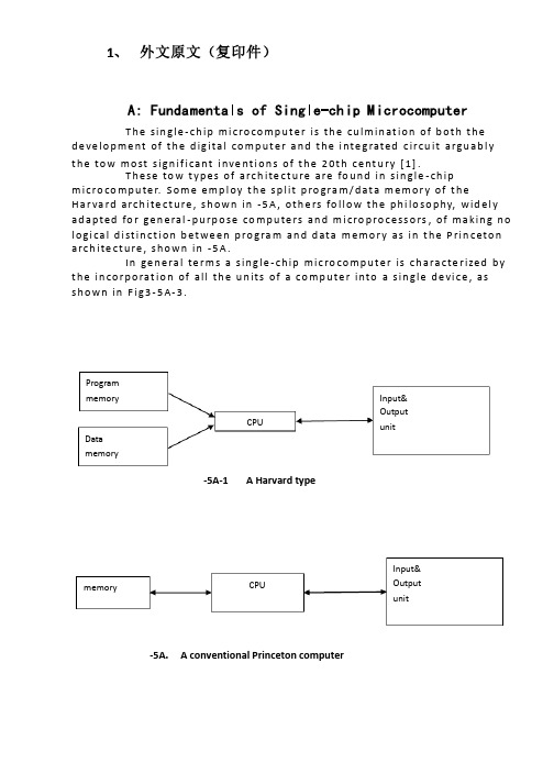
1、 外文原文(复印件)A: Fundamentals of Single-chip MicrocomputerT h e sin gle -ch ip mi c ro co m p u t e r is t h e cu lm in at io n of b ot h t h e d e ve lo p me nt of t h e d ig ita l co m p u t e r a n d t h e i nte g rated c ircu it a rgu ab l y t h e to w mo st s ign if i cant i nve nt i o n s of t h e 20t h c e nt u ry [1].T h ese to w t yp e s of arch ite ct u re are fo u n d in s in gle -ch ip m i cro co m p u te r. S o m e e mp l oy t h e sp l it p ro gra m /d at a m e m o r y of t h e H a r va rd arch ite ct u re , s h o wn in -5A , ot h e rs fo l lo w t h e p h i lo so p hy, wid e l y ad a p ted fo r ge n e ral -p u rp o se co m p u te rs an d m i cro p ro ce ss o rs , of m a kin g n o l o g i ca l d i st in ct i o n b et we e n p ro gra m an d d ata m e m o r y as in t h e P rin c eto n a rch ite ct u re , sh o wn in -5A.In ge n e ra l te r m s a s in g le -ch ip m ic ro co m p u t e r is ch a ra cte r ized b y t h e in co r p o rat io n of all t h e u n its of a co mp u te r into a s in gle d e vi ce , as s h o w n in F i g3-5A-3.-5A-1A Harvard type-5A. A conventional Princeton computerProgrammemory Datamemory CPU Input& Output unitmemoryCPU Input& Output unitResetInterruptsPowerFig3-5A-3. Principal features of a microcomputerRead only memory (ROM).RO M is u su a l l y fo r t h e p e r m an e nt , n o n -vo lat i le sto rage of an ap p l i cat io n s p ro g ram .M a ny m i c ro co m p u te rs a n d m i cro co nt ro l le rs are inte n d ed fo r h i gh -vo lu m e ap p l i cat io n s a n d h e n ce t h e e co n o m i cal man u fa c t u re of t h e d e vi ces re q u ires t h at t h e co nt e nts of t h e p ro gra m me mo r y b e co mm i ed p e r m a n e nt l y d u r in g t h e m a n u fa ct u re of c h ip s . C lea rl y, t h i s imp l ies a r i go ro u s ap p ro a ch to ROM co d e d e ve lo p m e nt s in ce ch an ges can n o t b e mad e af te r m an u fa ct u re .T h i s d e ve l o p m e nt p ro ces s m ay i nvo l ve e mu l at i o n u sin g a so p h ist icated d e ve lo p m e nt syste m wit h a h ard wa re e mu l at i o n capab i l it y as we ll as t h e u s e of p o we rf u l sof t war e to o l s.So m e m an u fa ct u re rs p ro vi d e ad d it i o n a l ROM o p t io n s b y in clu d in g in t h e i r ran ge d e v ic es w it h (o r inte n d ed fo r u s e wit h ) u se r p ro g ram m a b le m e mo r y. T h e s im p lest of t h e se i s u su a l l y d e v i ce wh i ch can o p e rat e in a m i cro p ro ce s so r mo d e b y u s in g s o m e of t h e in p u t /o u t p u t l in es as an ad d res s a n d d ata b u s fo r a cc es sin g exte rn a l m e m o r y. T h is t yp e o f d e vi ce can b e h ave f u n ct i o n al l y as t h e s in gle ch ip m i cro co m p u t e r f ro m wh i ch it i s d e ri ved a lb e it wit h re st r icted I/O an d a m o d if ied exte rn a l c ircu it. T h e u s e of t h e se RO M le ss d e vi ces i s co mmo n e ve n in p ro d u ct io n circu i ts wh e re t h e vo lu m e d o e s n ot ju st if y t h e d e ve lo p m e nt co sts of cu sto m o n -ch ip ROM [2];t h e re ca n st i ll b e a si gn if i cant sav in g in I/O an d o t h e r ch ip s co m pared to a External Timing components System clock Timer/ Counter Serial I/O Prarallel I/O RAM ROMCPUco nve nt io n al m i c ro p ro ces so r b ased circ u it. M o re exa ct re p l a ce m e nt fo rRO M d e v ice s can b e o b tain ed in t h e fo rm of va ria nts w it h 'p i g g y-b a c k'E P ROM(E rasab le p ro gramm ab le ROM )s o cket s o r d e v ice s w it h E P ROMin stead of ROM 。
电气外文文献-翻译
Circuit breaker断路器Compressed air circuit breaker is a mechanical switch equipment, can be i 空气压缩断路器是一种机械开关设备,能够在n normal and special conditions breaking current (such as short circuit cur 正常和特殊情况下开断电流(比如说短路电流)。
rent). For example, air circuit breaker, oil circuit breaker, interference circ 例如空气断路器、油断路器,干扰电路的导体uit conductor for the application of the safety and reliability of the circuit 干扰电路的导体因该安全可靠的应用于其中,breaker, current in arc from is usually divided into the following grades: a 电流断路器按灭弧远离通常被分为如下等级:ir switch circuit breaker, oil circuit breaker, less oil circuit breaker, compr 空气开关断路器、油断路器、少油断路器、压缩空essed air circuit breaker, a degaussing of isolating switch, six sulfur hexaf 气断路器、具有消磁性质的隔离开关、六氟luoride circuit breaker and vacuum breaker. Their parameters of voltage, 化硫断路器和真空断路器。
他们的参数有电压等级、current, insulation level of breaking capacity, instantaneous voltage off ti 开断容量的电流、绝缘等级开断时间的瞬时电压恢复和me of recovery and a bombing. Breaker plate usually include: 1 the maxi 轰炸时间。
电气专业毕业设计英文文献
电气专业毕业设计英文文献电气专业毕业设计英文文献外文资料与中文翻译外文资料:Relay protection present situation anddevelopment一、Relay protection development present situationElectrical power system's swift development to the relay protection proposed unceasingly the new request, the electronic technology, the computer technology and communication's swift development unceasingly has infused the new vigor for the relay protection technology's development, therefore, the relay protection technology is advantageous, has completed the development 4 historical stage in 40 remaining years of time.After the founding of the nation, our country relay protection discipline, the relay protection design, the relay factory industry and the relay protection technical team grows out of nothing, has passed through the path which in about 10 year the advanced countries half century pass through. In the 50s, our country engineers and technicians creatively absorption, the digestion, have grasped the overseas advanced relay protection equipment performance and the movement technology [1], completed one to have the deep relay protection theory attainments and the rich service experience's relay protection technical team, and grew the instruction function to the national relay protection technical team's establishment. The Achengrelay factory introduction has digested at that time the overseas advanced relay technique of manufacture, has established our country own relay manufacturing industry.Therefore our country has completed the relay protection research, the design, the manufacture, the movement and the teaching complete system in the 60s. This is the mechanical and electrical -like relay protection prosperous time, was our country relay protection technology development has laid the solid foundation.From the late 50s, the transistor relay protection was starting to study. In the 60s to the 80s in is the time which the transistor relay protection vigorous development and widely uses. And the Tianjin University and the Nanjing Electric power Automation Plant cooperation research's 500kv transistor direction high frequency protection develops with the Nanjing Electric power Automation Research institute the transistor high frequency block system is away from the protection, moves on the Gezhou Dam 500 kv lines [2], finished the 500kv line protection to depend upon completely from the overseas import time.From the 70s, started based on the integration operational amplifier's integrated circuit protection to study. Has formed the complete series to the late 80s integrated circuit protection, substitutes for the transistor protection gradually. The development which, the production, the application protected to the early 90s integrated circuit were still in the dominant position, this was theintegrated circuit protection time. The integrated circuit power frequency change quantity direction which develops in this aspect Nanjing Electric power Automation Research institute high frequency protected the influential role [3], the Tianjin University and the Nanjing Electric power Automation Plant cooperation development's integrated circuit phase voltage compensation type direction high frequency protection alsomoved in many 220kv and on the 500kv line.Our country namely started the computer relay protection research from the late 70s [4], the institutions of higher learning and the scientific research courtyard institute forerunner's function. Huazhong University of Science and Technology, the Southeast University, the North China electric power institute, Xi'an Jiaotong University, the Tianjin University, Shanghai Jiaotong University, the Chongqing University and the Nanjing Electric power Automation Research institute one after another has developed the different principle, the different pattern microcomputer protective device. in 1984 the original North China electric power institute developed the transmission line microcomputer protective device first through the appraisal, and obtained the application in the system [5], has opened in our country relay protection history the new page, protected the promotion for the microcomputer to pave the way. In the main equipment protection aspect, the generator which the Southeast University and Huazhong University of Science and Technology develops loses magnetism protection, the generator protection and the generator? Bank of transformers protectionalso one after another in 1989, in 1994 through appraisal, investment movement. The Nanjing Electric power Automation Research institute develops microcomputer line protective device alsoin 1991 through appraisal. Tianjin University and Nanjing Electric power Automation Plant cooperation development microcomputer phase voltage compensation type direction high frequency protection, Xi'an Jiaotong University and Xuchang relay factory cooperation development positive sequence breakdown component direction high frequencyprotection also one after another in 1993, in 1996 through appraisal. Hence, the different principle, the different type's microcomputer line and the main equipment protect unique, provided one group of new generation performance for the electrical power system to be fine, the function was complete, operation reliable relay protection installment. Along with the microcomputer protective device's research, in microcomputer aspects and so on protection software, algorithm has also made many theory progresses. May say that started our country relay protection technology from the 90s to enter the time which the microcomputer protected.二、future development of Relay protectionThe future trend of relay protection technology is to computerization, networking is intelligent, protect, control, measure and data communication developing by integration. The principles of protection of electric power circuits are quite independent of the relay designs which may be applied. For example, if the current to an electriccircuit or a machine is greater than that which can be tolerated, it is necessary to take remedial action. The device for recognizing the condition and initiating corrective measures would be termed as an over-current relay regardless of the mechanists by whichthe function would be accomplished. Because the functions of electromechanical devices are easily described, their performance wills ever as a basis for presenting a description of relays and relay systemsin general.Relays must have the following characteristics: Reliability---The nature of the problem is that the relay may be idle for periods extending into years and then be required tooperatewith fast responds, as intended, the first time. The penalty for failure to operate properly may run into millions of dollars.Selectivity---The relay must not respond to abnormal, but harmless, system conditions such as switching transients or sudden changes in load.Sensitivity---The relay must not fail to operate, even in borderline situations, when operation was planned.Speed---The relay should make the decision to act as close to instantaneously as possible. If intentional time delay is available, it should be predictable and precisely adjustable.Instantaneous---The term means no intentional time delay.There are several possible ways to classify relays: by function, by construction, by application. Relays are one of two basic types of construction: electromagnetic or solid-state. The electromagnetic type relies on the development of electromagnetic forces on movable members,which provide switching action by physically opening or closing sets of contacts. The solid state variety provides switching action with no physical motion by changing the state of serially connected solid state component from no conducting to conducting(or vice versa). Electromagnetic relays are older and more widely used; solid state relays are more versatile, potentially more reliable, and fast.1)ComputerizationWith swift and violent development of computer hardware, computer protect hardware develop constantly even. The power system is improving to the demand that the computer protects constantly, besides basic function protected, should with trouble information of the large capacity and data the long-term parkingspace also, fast data processing function, strong communication capacity, network in order to share the whole system data , information , ability , network of resource with other protection , control device , dispatcher, high-level language programming ,etc.. This requires computer protector to have function which is equivalent to a pc machine. In computer is it develop initial stage to protect, is it make with one minicom relay protection install to imagine. Because the small-scale organism was accumulated greatly, with high costs at that time, dependability was bad, this imagined it was unrealistic . Now, exceed the minicomputer of those years greatly with computer protector size similar worker function , speed , memory capacity of accusing of machine, so make with complete sets of worker person who accuse of opportunity of relay protection already ripe, this will be one of the developing direction that a computer is protected . Tianjin university is it spend whom transformation act as continue the electric protector with computer protector structure self-same one worker person whoaccuse of to develop into already. The advantage of this kind of device is as follows, (1)it have functions of 486pc,it can meet to at present and it is various kinds of function demand where computerprotect future. (2)The size and structure are similar to present computer protector , the craft is superior, takes precautions against earthquakes , defends overheatedly and defending the electromagnetic ability of interfering strongly, can operate it in very abominable working environment , the cost is acceptable.(3)Adopting std bus or pc bus, hardware module , can select different module for use to different protection wantonly , it is flexible , easy to expand to dispose.It is an irreversible development trend to continue the computer , computerization of the electric protector. But to how better meet power system demand, how about raise the dependability of relay protection further, how make heavy economic benefits and social benefit, need carry on concrete deep research.2) NetworkedComputer network become the technological pillar of information age as message and data communication tool, made the mankind producing , basic change has taken place in the appearance with social life. It isinfluencing each industrial field deeply, has offered the powerful communication means for each industrial field too. Up till now, except that protect differentially and unite protecting vertically, all continue electric protector can only react that protect the electric quantity of installing office. The function of relay protection is only limited to excising the trouble component too , narrow the accident coverage. This mainly lack the powerful data communication means. Having already put forward the concept protected systematically abroad, this meant the safe automatics mainly at that time. Because the function of relay protection is not only limited to excising the trouble component and restriction accident coverage (this is primary task), the peace and steadiness that will be guaranteed the whole system run . This require each protect unit can share the whole operation and data , trouble of information of system, each protect unit and coincident floodgate device coordination on the basis of analysing the information and data, guarantee systematic peace and steadiness run . Obviously , realize the primary condition that system protect the whole system every protector of capitalequipment link with the computer network, namely the one that realized the computer protector is networked. This is totally possible under present technological condition .To general protecting systematically , realize the computer networking of the protector has a very great advantage too. It continue electric trouble not the less many in information not systematic can receiving protector ,for trouble nature , judgement and the trouble,trouble of position from measuring the less accurate. Protect to self-adaptation research of principle pass long time very already , make certain achievement too, but should really realize protecting the self-adaptation to the operation way of the system and trouble state, must obtain more system operating and trouble information , the computer that only realizes protecting is networked, could accomplish this . As to the thing that some protectors realize computer networking , can improve the dependability protected . Tianjin Sanxia vltrahigh voltage many return circuit bus bar , 500kv of power station , put forward one distributed principle that bus bar protected to future 1993 such as university, succeed in developing this kind of device tentatively. Principle its bus bar is it disperse several (with protect into bus bar back to way the same ) bus bar protect Entrance to protect traditional concentration type, disperse and install it in every return circuit is protected and rejected , each protect the unit to link with the computer network, each one protects the electric current amount that the unit only inputs a return circuit , after changing it into figure amount, convey to the protection units of other return circuits through the computer network, each protect the unit according to the electric current amount of this return circuit and electric current amount of other return circuits gotfrom computer network, carry on bus bar differential calculation that protect, if result of calculation prove bus bar trouble jump format return circuit circuit breaker only, isolate the bus bar of the trouble. At the time of the trouble outside the bus bar district , each protect the unit and calculate for movements of the external trouble. This kind protect principle by distributed bus barthat network realize with computer, bus bar protect principle have higher dependability than traditional concentration type. Because if one protect unit interfere or mistake in computation and when working up by mistake, can only jump format return circuit , can is it make bus bar to be whole of malignant accident that excise to cause wrong, this is very important to systematic pivot with supervoltage bus bar of hydropower station like SanxiaCan know computer protector networked to can raise and protect the performance and dependability greatly while being above-mentioned, this is an inexorable trend that a computer protects development 3) Protect , control , measure , data communication integratesOn terms that realize computerization of relay protection and networked, the protector is a high performance , multi-functional computer in fact, it is a intelligent terminal on the computer network of whole power system. It can obtain any information and data of operating and trouble of the power system from network , can convey network control centre or any terminal function , and can also finish the measurement , control , data communication function in there is no normal running of trouble cases, namely realize protecting ,controlling , measuring , data communication integrates.At present, for measurement, need that protects and controlling, all equipment of the outdoor transformer substation, two voltage, electric current of voltage transformer, circuit,etc. must with control cable guide to the top management room for instance. Lay control cable take a large amount of investment, make the very much complicated returncircuit 2 times in a large amount. But if above-mentioned protection, control, measure, data communication integrated computer device, install in to is it by the equipment , protect into voltage , electric current amount of equipment in device this after changing into the figure amount to protect outdoor transformer substation on the spot, send to the top management room through the computer network, can avoid a large number of controlcables . If use optic fibre as the transmission medium of the network , can avoid and interfere electromagnetically. The photocurrent mutual inductor of now (ota ) and photovoltage mutual inductor (otv ) have been already during the course of studying and testing, must get application in the power system in the future. In case of adopting ota and otv, namely should be putting and is being protected near the equipment.After the optical signals of ota and otv are input in the integrated device here and changes into an electric signal, what is on one hand uses as being protected calculation is judged ; As measurement amount on the other hand, send to the top management room through the network. Can to protect operation of equipment control order send this integrated device to through network from top management room, therefore the integrated device carries out the operation of the circuit breaker. The university of Tianjin put forward protecting,controlled , measured , communication integration in 1992, develop based on tms320c25 digital signal processor (dsp ) first protecting , control , measure , the integrated device of data communication.4)IntelligentIn recent years, if artificial intelligence technology neural network, hereditary algorithm, evolve plan , fuzzy logic ,etc. get application in power system all field, the research that is used in the field of relay protection has already begun too. Neural network one non-linear method that shine upon, a lot of difficult to list equation or difficult in order to the complicated non-linear question that is solved, use the method of the neural network to be very easily solved .For example the short circuit of crossing the resistance of courseof emergence is a non-linear problem in transmit electricity in the systematic electric potential angle of both sides of line and lay cases, it is very difficult to make discrimination , trouble of position while being correct for distance to protect, is it work up or is it work up to refuse by mistake to lead to the fact; If use neural network method, through a large number of trouble training of sample, so long as sample centralized to fully consider various kinds of situations, can differentiate correctly while any trouble takes place. Other if hereditary algorithm , is it is it have is it solve complicated abilityof problem to asking unique their too to plan to evolve. Artificial intelligence the being method proper to is it can make it solve speed to be fast not to ask to combine. Can predict , the artificial intelligence technology must get application in the field of relay protection, in order to solve the problem difficult to solvewith the routine method.中文翻译:继电保护的现状与发展一、继电保护发展现状电力系统的飞速发展对继电保护不断提出新的要求,电子技术、计算机技术与通信技术的飞速发展又为继电保护技术的发展不断地注入了新的活力,因此,继电保护技术得天独厚,在40余年的时间里完成了发展的4个历史阶段。
(完整版)电气专业中英文对照翻译毕业设计论文

优秀论文审核通过未经允许切勿外传Chapter 3 Digital Electronics3.1 IntroductionA circuit that employs a numerical signal in its operation is classified as a digital circuitputers,pocket calculators, digital instruments, and numerical control (NC) equipment are common applications of digital circuits. Practically unlimited quantities of digital information can be processed in short periods of time electronically. With operational speed of prime importance in electronics today,digital circuits are used more frequently.In this chapter, digital circuit applications are discussed.There are many types of digital circuits that electronics, including logic circuits, flip-flop circuits, counting circuits, and many others. The first sections of this unit discuss the number systems that are basic to digital circuit understanding. The remainder of the chapter introduces some of the types of digital circuits and explains Boolean algebra as it is applied to logic circuits.3.2 Digital Number SystemsThe most common number system used today is the decimal system,in which 10 digits are used for counting. The number of digits in the systemis called its base (or radix).The decimal system,therefore,the counting process. The largest digit that can be used in a specific place or location is determined by the base of the system. In the decimal system the first position to the left of the decimal point is called the units place. Any digit from 0 to 9 can be used in this place.When number values greater than 9 are used,they must be expressed with two or more places.The next position to the left of the units place in a decimal system is the tens place.The number 99 is the largest digital value that can be expressed by two places in the decimal system.Each place added to the left extends the number system by a power of 10.Any number can be expressed as a sum of weighted place values.The decimal number 2583,for example, is expressed as (2×1000)+(5×100)+(8×10)+(3×1).The decimal number system is commonly used in our daily lives. Electronically, the binary system.Electronically,the value of 0 can be associated with a low-voltage value or no voltage. The number 1 can then be associated with a voltage value larger than 0. Binary systems that use these voltage values are said to , this chapter.The two operational states of a binary system,1 and 0,are natural circuit conditions. When a circuit is turned off or the off, or 0,state. An electrical circuit that the on,or 1,state. By using transistor or ICs,it is electronically possible to change states in less than a microsecond. Electronic devices make it possible to manipulate millions of 0s and is in a second and thus to process information quickly.The basic principles of numbering used in decimal numbers apply ingeneral to binary numbers.The base of the binary system is 2,meaning that only the digits 0 and 1 are used to express place value. The first place to the left of the binary point,or starting point,represents the units,or is,location. Places to the left of the binary point are the powers of 2.Some of the place values in base 2 are 2º=1,2¹=2,2²=4,2³=8,2⁴=16,25=32,and 26=64.When bases other than 10 are used,the numbers should example.The number 100₂(read“one,zero,zero, base 2”)is equivalent to 4 in base 10,or 410.Starting with the first digit to the left of the binary point,this number this method of conversion a binary number to an equivalent decimal number,write down the binary number first. Starting at the binary point,indicate the decimal equivalent for each binary place location where a 1 is indicated. For each 0 in the binary number leave a blank space or indicate a 0 ' Add the place values and then record the decimal equivalent.The conversion of a decimal number to a binary equivalent is achieved by repetitive steps of division by the number 2.When the quotient is even with no remainder,a 0 is recorded.When the quotient process continues until the quotient is 0.The binary equivalent consists of the remainder values in the order last to first.3.2.2 Binary-coded Decimal (BCD) Number SystemWhen large numbers are indicated by binary numbers,they are difficult to use. For this reason,the Binary-Coded Decimal(BCD) method of counting was devised. In this system four binary digits are used to represent each decimal digit.To illustrate this procedure,the number 105,is converted to a BCD number.In binary numbers,To apply the BCD conversion process,the base 10 number is first divided into digits according to place values.The number 10510 gives the digits 1-0-5.Converting each displayed by this process with only 12 binary numbers. The between each group of digits is important when displaying BCD numbers.The largest digit to be displayed by any group of BCD numbers is 9.Six digits of a number-coding group are not used at all in this system.Because of this, the octal (base 8) and the binary form but usually display them in BCD,octal,or a base 8 system is 7. The place values starting at the left of the octal point are the powers of eight: 80=1,81=8,82=64,83=512,84=4096,and so on.The process of converting an octal number to a decimal number is the same as that used in the binary-to-decimal conversion process. In this method, equivalent decimal is 25810.Converting an octal number to an equivalent binary number is similar to the BCD conversion process. The octal number is first divided into digits according to place value. Each octal digit is then converted into an equivalent binary number using only three digits.Converting a decimal number to an octal number is a process of repetitive division by the number 8.After the quotient determined,the remainder is brought down as the place value.When the quotient is even with no remainder,a 0 is transferred to the place position.The number for converting 409810 to base 8 is 100028.Converting a binary number to an octal number is an importantconversion process of digital circuits. Binary numbers are first processed at a very output circuit then accepts this signal and converts it to an octal signal displayed on a readout device.must first be divided into groups of three,starting at the octal point.Each binary group is then converted into an equivalent octal number.These numbers are then combined,while remaining in their same respective places,to represent the equivalent octal number.3.2.4 Hexadecimal Number SystemThe digital systems to process large number values.The base of this system is 16,which means that the largest number used in a place is 15.Digits used by this system are the numbers 0-9 and the letters A-F. The letters A-P are used to denote the digits 10-15,respectively. The place values to the left of the .The process of changing a proper digital order.The place values,or powers of the base,are then positioned under the respective digits in step 2.In step 3,the value of each digit is recorded. The values in steps 2 and 3 are then multiplied together and added. The sum gives the decimal equivalent value of a . Initially,the converted to a binary number using four digits per group. The binary group is combined to form the equivalent binary number.The conversion of a decimal number to a ,as with other number systems. In this procedure the division is by 16 and remainders can be as large as 15.Converting a binary number to a groups of four digits,starting at the converted to a digital circuit-design applications binary signals arefar superior to those of the octal,decimal,or be processed very easily through electronic circuitry,since they can be represented by two stable states of operation. These states can be easily defined as on or off, 1 or 0,up or down,voltage or no voltage,right or left,or any other two-condition states. There must be no in-between state.The symbols used to define the operational state of a binary system are very important.In positive binary logic,the state of voltage,on,true,or a letter designation (such as A ) is used to denote the operational state 1 .No voltage,off,false,and the letter A are commonly used to denote the 0 condition. A circuit can be set to either state and will remain in that state until it is caused to change conditions.Any electronic device that can be set in one of two operational states or conditions by an outside signal is said to be bistable. Relays,lamps,switches,transistors, diodes and ICs may be used for this purpose. A bistable device .By using many of these devices,it is possible to build an electronic circuit that will make decisions based upon the applied input signals. The output of this circuit is a decision based upon the operational conditions of the input. Since the application of bistable devices in digital circuits makes logical decisions,they are commonly called binary logic circuits.If we were to draw a circuit diagram for such a system,including all the resistors,diodes,transistors and interconnections,we would face an overwhelming task, and an unnecessary one.Anyone who read the circuit diagram would in their mind group the components into standard circuits and think in terms of the" system" functions of the individual gates. Forthis reason,we design and draw digital circuit with standard logic symbols. Three basic circuits of this type are used to make simple logic decisions.These are the AND circuit, OR circuit, and the NOT circuit.Electronic circuits designed to perform logic functions are called gates.This term refers to the capability of a circuit to pass or block specific digital signals.The logic-gate symbols are shown in Fig.3-1.The small circle at the output of NOT gate indicates the inversion of the signal. Mathematically,this action is described as A=.Thus without the small circle,the rectangle would represent an amplifier (or buffer) with a gain of unity.An AND gate the 1 state simultaneously,then there will be a 1 at the output.The AND gate in Fig. 3-1 produces only a 1 out-put when A and B are both 1. Mathematically,this action is described as A·B=C. This expression shows the multiplication operation. An OR gate Fig.3-1 produces a when either or both inputs are l.Mathematically,this action is described as A+B=C. This expression shows OR addition. This gate is used to make logic decisions of whether or not a 1 appears at either input.An IF-THEN type of sentence is often used to describe the basic operation of a logic state.For example,if the inputs applied to an AND gate are all 1,then the output will be 1 .If a 1 is applied to any input of an OR gate,then the output will be 1 .If an input is applied to a NOT gate,then the output will be the opposite or inverse.The logic gate symbols in Fig. 3-1 show only the input and output connections. The actual gates,when wired into a digital circuit, would pin 14 and 7.3.4 Combination Logic GatesWhen a NOT gate is combined with an AND gate or an OR gate,it iscalled a combination logic gate. A NOT-AND gate is called a NAND gate,which is an inverted AND gate. Mathematically the operation of a NAND gate is A·B=. A combination NOT-OR ,or NOR,gate produces a negation of the OR function.Mathematically the operation of a NOR gate is A+B=.A 1 appears at the output only when A is 0 and B is 0.The logic symbols are shown in Fig. 3-3.The bar over C denotes the inversion,or negative function,of the gate.The logic gates discussed .In actual digital electronic applications,solid-state components are ordinarily used to accomplish gate functions.Boolean algebra is a special form of algebra that was designed to show the relationships of logic operations.Thin form of algebra is ideally suited for analysis and design of binary logic systems.Through the use of Boolean algebra,it is possible to write mathematical expressions that describe specific logic functions.Boolean expressions are more meaningful than complex word statements or or elaborate truth tables.The laws that apply to Boolean algebra are used to simplify complex expressions. Through this type of operation it may be possible to reduce the number of logic gates needed to achieve a specific function before the circuits are designed.In Boolean algebra the variables of an equation are assigned by letters of the alphabet.Each variable then exists in states of 1 or 0 according to its condition.The 1,or true state,is normally represented by a single letter such as A,B or C.The opposite state or condition is then described as 0,or false,and is represented by or A’.This is described as NOT A,A negated,or A complemented.Boolean algebra is somewhat different from conventional algebra withrespect to mathematical operations.The Boolean operations are expressed as follows:Multiplication:A AND B,AB,,A·BOR addition:A OR B .A+BNegation,or complementing:NOT A,,A’Assume that a digital logic circuit only C is on by itself or when A,B and C are all on expression describes the desired output. Eight (23) different combinations of A,B,and C exist in this expression because there are three,inputs. Only two of those combinations should cause a signal that will actuate the output. When a variable is not on (0),it is expressed as a negated letter. The original statement is expressed as follows: With A,B,and C on or with A off, B off, and C on ,an output (X)will occur:ABC+C=XA truth table illustrates if this expression is achieved or not.Table 3-1 shows a truth table for this equation. First,ABC is determined by multiplying the three inputs together.A 1 appears only when the A,B,and C inputs are all 1.Next the negated inputs A andB are determined.Then the products of inputs C,A,and B are listed.The next column shows the addition of ABC and C.The output of this equation shows that output 1 is produced only when C is 1 or when ABC is 1.A logic circuit to accomplish this Boolean expression is shown in Fig. 3-4.Initially the equation is analyzed to determine its primary operational function.Step1 shows the original equation.The primary function is addition,since it influences all parts of the equation in some way.Step 2 shows the primary function changed to a logic gate diagram.Step 3 showsthe branch parts of the equation expressed by logic diagram,with AND gates used to combine terms.Step 4 completes the process by connecting all inputs together.The circles at inputs,of the lower AND gate are used to achieve the negative function of these branch parts.The general rules for changing a Boolean equation into a logic circuit diagram are very similar to those outlined.Initially the original equation must be analyzed for its primary mathematical function.This is then changed into a gate diagram that is inputted by branch parts of the equation.Each branch operation is then analyzed and expressed in gate form.The process continues until all branches are completely expressed in diagram formmon inputs are then connected together.3.5 Timing and Storage ElementsDigital electronics involves a number of items that are not classified as gates.Circuits or devices of this type the operation of a system.Included in this system are such things as timing devices,storage elements,counters,decoders,memory,and registers.Truth tables symbols,operational characteristics,and applications of these items will be presented an IC chip. The internal construction of the chip cannot be effectively altered. Operation is controlled by the application of an external signal to the input. As a rule,very little work can be done to control operation other than altering the input signal.The logic circuits in Fig. 3-4 are combinational circuit because the output responds immediately to the inputs and there is no memory. When memory is a part of a logic circuit,the system is called sequential circuit because its output depends on the input plus its an input signal isapplied.A bistable multivibrator,in the strict sense,is a flip-flop. When it is turned on,it assumes a particular operational state. It does not change states until the input is altered.A flip-flop opposite polarity.Two inputs are usually needed to alter the state of a flip-flop. A variety of names are used for the inputs.These vary a great deal between different flip-flops.1. R-S flip-flopsFig.3-5 shows logic circuit construction of an R-S flip-flop. It is constructed from two NAND gates. The output of each NAND provides one of the inputs for the other NAND. R stands for the reset input and S represents the set input.The truth table and logic symbol are shown in Fig. 3-6.Notice that the truth table is somewhat more complex than that of a gate. It shows, for example,the applied input, previous output,and resulting output.To understand the operation of an R-S flip-flop,we must first look at the previous outputs.This is the status of the output before a change is applied to the input. The first four items of the previous outputs are Q=1 and =0. The second four states this case of the input to NANDS is 0 and that is 0,which implies that both inputs to NANDR are 1.By symmetry,the logic circuit will also stable with Q0 and 1.If now R momentarily becomes 0,the output of NANDR,,will rise to resulting in NANDS be realized by a 0 at S.The outputs Q and are unpredictable when the inputs R and S are 0 states.This case is not allowed.Seldom would individual gates be used to construct a flip-flop,rather than one of the special types for the flip-flop packages on a single chipwould be used by a designer.A variety of different flip-flops are used in digital electronic systems today. In general,each flip-flop type R-S-T flip-flop for example .is a triggered R-S flip-flop. It will not change states when the R and S inputs assume a value until a trigger pulse is applied. This would permit a large number of flip-flops to change states all at the same time. Fig. 3-7 shows the logic circuit construction. The truth table and logic symbol are shown in Fig. 3-8. The R and S input are thus active when the signal at the gate input (T) is 1 .Normally,such timing,or synchronizing,signals are distributed throughout a digital system by clock pulses,as shown in Fig. 3-9.The symmetrical clock signal provides two times each period.The circuit can be designed to trigger at the leading or trailing edge of the clock. The logic symbols for edge trigger flip-flops are shown in Fig.3-10.2. J-K flip-flopsAnother very important flip-flop unpredictable output state. The J and K inputs addition to this,J-K flip-flops may employ preset and preclear functions. This is used to establish sequential timing operations. Fig.3-11 shows the logic symbol and truth table of a J-K flip-flop.3. 5. 2 CountersA flip-flop be used in switching operations,and it can count pulses.A series of interconnected flip-flops is generally called a register.Each register can store one binary digit or bit of data. Several flip-flops connected form a counter. Counting is a fundamental digital electronic function.For an electronic circuit to count,a number of things must beachieved. Basically,the circuit must be supplied with some form of data or information that is suitable for processing. Typically,electrical pulses that turn on and off are applied to the input of a counter. These pulses must initiate a state change in the circuit when they are received. The circuit must also be able to recognize where it is in counting sequence at any particular time. This requires some form of memory. The counter must also be able to respond to the next number in the sequence. In digital electronic systems flip-flops are primarily used to achieve counting. This type of device is capable of changing states when a pulse is applied,output pulse.There are several types of counters used in digital circuitry today.Probably the most common of these is the binary counter.This particular counter is designed to process two-state or binary information. J-K flip-flops are commonly used in binary counters.Refer now to the single J-K flip-flop of Fig. 3-11 .In its toggle state,this flip-flop is capable of achieving counting. First,assume that the flip-flop is in its reset state. This would cause Q to be 0 and Q to be 1 .Normally,we are concerned only with Q output in counting operations. The flip-flop is now connected for operation in the toggle mode. J and K must both be made the 1 state. When a pulse is applied to the T,or clock,input,Q changes to 1.This means that with one pulse applied,a 1 is generated in the output. The flip-flop the next pulse arrives,Q resets,or changes to 0. Essentially,this means that two input pulses produce only one output pulse. This is a divide-by-two function.For binary numbers,counting is achieved by a number of divide-by-two flip-flops.To count more than one pulse,additional flip-flops must be employed. For each flip-flop added to the counter,its capacity is increased by the power of 2. With one flip-flop the maximum count was 20,or 1 .For two flip-flops it would count two places,such as 20 and 21.This would reach a count of 3 or a binary number of 11.The count would be 00,01,10,and 11. The counter would then clear and return to 00. In effect, this counts four state changes. Three flip-flops would count three places,or 20,21,and 22.This would permit a total count of eight state changes.The binary values are 000,001,010,011,100,101,110 and 111.The maximum count is seven,or 111 .Four flip-flops would count four places,or 20,21,22,and 23.The total count would make 16 state changes. The maximum count would be 15,or the binary number 1111.Each additional flip-flop would cause this to increase one binary place.河南理工大学电气工程及其自动化专业中英双语对照翻译。
电气工程的外文文献(及翻译)
电气工程的外文文献(及翻译)文献一:Electric power consumption prediction model based on grey theory optimized by genetic algorithms本文介绍了一种基于混合灰色理论与遗传算法优化的电力消耗预测模型。
该模型使用时间序列数据来建立模型,并使用灰色理论来解决数据的不确定性问题。
通过遗传算法的优化,模型能够更好地预测电力消耗,并取得了优异的预测结果。
此模型可以在大规模电力网络中使用,并具有较高的可行性和可靠性。
文献二:Intelligent control for energy-efficient operation of electric motors本文研究了一种智能控制方法,用于电动机的节能运行。
该方法提供了一种更高效的控制策略,使电动机能够在不同负载条件下以较低的功率运行。
该智能控制使用模糊逻辑方法来确定最佳的控制参数,并使用遗传算法来优化参数。
实验结果表明,该智能控制方法可以显著降低电动机的能耗,节省电能。
文献三:Fault diagnosis system for power transformers based on dissolved gas analysis本文介绍了一种基于溶解气体分析的电力变压器故障诊断系统。
通过对变压器油中的气体样品进行分析,可以检测和诊断变压器内部存在的故障类型。
该系统使用人工神经网络模型来对气体分析数据进行处理和分类。
实验结果表明,该系统可以准确地检测和诊断变压器的故障,并有助于实现有效的维护和管理。
文献四:Power quality improvement using series active filter based on iterative learning control technique本文研究了一种基于迭代研究控制技术的串联有源滤波器用于电能质量改善的方法。
- 1、下载文档前请自行甄别文档内容的完整性,平台不提供额外的编辑、内容补充、找答案等附加服务。
- 2、"仅部分预览"的文档,不可在线预览部分如存在完整性等问题,可反馈申请退款(可完整预览的文档不适用该条件!)。
- 3、如文档侵犯您的权益,请联系客服反馈,我们会尽快为您处理(人工客服工作时间:9:00-18:30)。
外文翻译院(系)专业班级姓名学号指导教师年月日Programmable designed for electro-pneumatic systemscontrollerJohn F.WakerlyThis project deals with the study of electro-pneumatic systems and the programmable controller that provides an effective and easy way to control the sequence of the pneumatic actuators movement and the states of pneumatic system. The project of a specific controller for pneumatic applications join the study of automation design and the control processing of pneumatic systems with the electronic design based on microcontrollers to implement the resources of the controller.1. IntroductionThe automation systems that use electro-pneumatic technology are formed mainly by three kinds of elements: actuators or motors, sensors or buttons and control elements like valves. Nowadays, most of the control elements used to execute the logic of the system were substituted by the Programmable Logic Controller (PLC). Sensors and switches are plugged as inputs and the direct control valves for the actuators are plugged as outputs. An internal program executes all the logic necessary to the sequence of the movements, simulates other components like counter, timer and control the status of the system.With the use of the PLC, the project wins agility, because it is possible to create and simulate the system as many times as needed. Therefore, time can be saved, risk of mistakes reduced and complexity can be increased using the same elements.A conventional PLC, that is possible to find on the market from many companies, offers many resources to control not only pneumatic systems, but all kinds of system that uses electrical components. The PLC can be very versatile and robust to be applied in many kinds of application in the industry or even security system and automation of buildings.Because of those characteristics, in some applications the PLC offers to much resources that are not even used to control the system, electro-pneumatic system is one of this kind of application. The use of PLC, especially for small size systems, can be very expensive for the automation project.An alternative in this case is to create a specific controller that can offer the exactly size and resources that the project needs [3, 4]. This can be made using microcontrollers as the base of this controller.The controller, based on microcontroller, can be very specific and adapted to only one kind of machine or it can work as a generic controller that can be programmed as a usual PLC and work with logic that can be changed. All these characteristics depend on what is needed and how much experience the designer has with developing an electronic circuit and firmware for microcontroller. But the main advantage of design the controller with the microcontroller is that the designer has the total knowledge of his controller, which makes it possible to control the size of the controller, change the complexity and the application of it. It means that the project gets more independence from other companies, but at the same time the responsibility of the control of the system stays at the designer hands2. Electro-pneumatic systemOn automation system one can find three basic components mentioned before, plus a logic circuit that controls the system. An adequate technique is needed to project the logic circuit and integrate all the necessary components to execute the sequence of movements properly.For a simple direct sequence of movement an intuitive method can be used [1, 5], but for indirect or more complex sequences the intuition can generate a very complicated circuit and signal mistakes. It is necessary to use another method that can save time of the project, makea clean circuit, can eliminate occasional signal overlapping and redundant circuits. The presented method is called step-by-step or algorithmic [1, 5], it is valid for pneumatic and electro-pneumatic systems and it was used as a base in this work.The method consists of designing the systems based on standard circuits made for each change on the state of the actuators, these changes are called steps.The first part is to design those kinds of standard circuits for each step, the next task is to link the standard circuits and the last part is to connect the control elements that receive signals from sensors, switches and the previous movements, and give the air or electricity to the supply lines of each step. In Figs. 1 and 2 the standard circuits are drawn for pneumatic and electro-pneumatic system [8]. It is possible to see the relations with the previous and the next steps.3. The method applied inside the controllerThe result of the method presented before is a sequence of movements of the actuator that is well defined by steps. It means that each change on the position of the actuators is a new state of the system and the transition between states is called step.The standard circuit described before helps the designer to define the states of the systems and to define the condition to each change between the states. In the end of the design, the system is defined by a sequence that never chances and states that have the inputs and the outputs well defined. The inputs are the condition for the transition and the outputs are the result of the transition.All the configuration of those steps stays inside of the microcontroller and is executed the same way it was designed. The sequences of strings are programmed inside the controller with 5 bytes; each string has the configuration of one step of the process. There aretwo bytes for the inputs, one byte for the outputs and two more for the other configurations and auxiliary functions of the step. After programming, this sequence of strings is saved inside of a non-volatile memory of the microcontroller, so they can be read and executed.The controller task is not to work in the same way as a conventional PLC, but the purpose of it is to be an example of a versatile controller that is design for an specific area. A conventional PLC process the control of the system using a cycle where it makes an image of the inputs, execute all the conditions defined by the configuration programmed inside, and then update the state of the outputs. This controller works in a different way, where it read the configuration of the step, wait the condition of inputs to be satisfied, then update the state or the outputs and after that jump to the next step and start the process again.It can generate some limitations, as the fact that this controller cannot execute, inside the program, movements that must be repeated for some time, but this problem can be solved with some external logic components. Another limitation is that the controller cannot be applied on systems that have no sequence. These limitations are a characteristic of the system that must be analyzed for each application.4. Characteristics of the controllerThe controller is based on the MICROCHIP microcontroller PIC16F877 [6,7] with 40 pins, and it has all the resources needed for this project .It has enough pins for all the components, serial communication implemented in circuit, EEPROM memory to save all the configuration of the system and the sequence of steps. For the execution of the main program, it offers complete resources as timers and interruptions.The list of resources of the controller was created to explore all the capacity of the microcontroller to make it as complete as possible. During the step, the program chooses how to use the resources reading theconfiguration string of the step. This string has two bytes for digital inputs, one used as a mask and the other one used as a value expected. One byte is used to configure the outputs value. One bytes more is used for the internal timer , the analog input or time-out. The EEPROM memory inside is 256 bytes length that is enough to save the string of the steps, with this characteristic it is possible to save between 48 steps (Table 1).The controller (Fig.3) has also a display and some buttons that are used with an interactive menu to program the sequence of steps and other configurations.4.1. Interaction componentsFor the real application the controller must have some elements to interact with the final user and to offer a complete monitoring of the system resources that are available to the designer while creating the logic control of the pneumatic system (Fig.3):•Interactive mode of work; function available on the main program for didactic purposes, the user gives the signal to execute the step.•LCD display, which shows the status of the system, values of inputs, outputs, timer and statistics of the sequence execution.•Beep to give important alerts, stop, start and emergency.• Leds to show power on and others to show the state of inputs and outputs.4.2. SecurityTo make the final application works property, a correct configuration to execute the steps in the right way is needed, but more then that it must offer solutions in case of bad functioning or problems in the execution of the sequence. The controller offers the possibility to configure two internal virtual circuits that work in parallel to the principal. These two circuits can be used as emergency or reset buttons and can return the system to a certain state at any time [2]. There aretwo inputs that work with interruption to get an immediate access to these functions. It is possible to configure the position, the buttons and the value of time-out of the system.4.3. User interfaceThe sequence of strings can be programmed using the interface elements of the controller. A Computer interface can also be used to generate the user program easily. With a good documentation the final user can use the interface to configure the strings of bytes that define the steps of the sequence. But it is possible to create a program with visual resources that works as a translator to the user, it changes his work to the values that the controller understands.To implement the communication between the computer interface and the controller a simple protocol with check sum and number of bytes is the minimum requirements to guarantee the integrity of the data.4.4. FirmwareThe main loop works by reading the strings of the steps from the EEPROM memory that has all the information about the steps.In each step, the status of the system is saved on the memory and it is shown on the display too. Depending of the user configuration, it can use the interruption to work with the emergency circuit or time-out to keep the system safety. In Fig.4,a block diagram of micro controller main program is presented.5. Example of electro-pneumatic systemThe system is not a representation of a specific machine, but it is made with some common movements and components found in a real one. The system is composed of four actuators. The actuators A, B and C are double acting and D-single acting. Actuator A advances and stays in specified position till the end of the cycle, it could work fixing an object to the next action for example (Fig. 5) , it is the first step. When A reachesthe end position, actuator C starts his work together with B, making as many cycles as possible during the advancing of B. It depends on how fast actuator B is advancing; the speed is regulated by a flowing control valve. It was the second step. B and C are examples of actuators working together, while B pushes an object slowly, C repeats its work for some time.When B reaches the final position, C stops immediately its cycle and comes back to the initial position. The actuator D is a single acting one with spring return and works together with the back of C, it is the third step. D works making very fast forward and backward movement, just one time. Its backward movement is the fourth step. D could be a tool to make a hole on the object.When D reaches the initial position, A and B return too, it is the fifth step.Fig. 6 shows the first part of the designing process where all the movements of each step should be defined [2]. (A+) means that the actuator A moves to the advanced position and (A−) to the initial position. The movements that happen at the same time are joined together in the same step. The system has five steps.These two representations of the system (Figs. 5 and 6) together are enough to describe correctly all the sequence. With them is possible to design the whole control circuit with the necessary logic components. But till this time, it is not a complete system, because it is missing some auxiliary elements that are not included in this draws because they work in parallel with the main sequence.These auxiliary elements give more function to the circuit and are very important to the final application; the most important of them is the parallel circuit linked with all the others steps. That circuit should be able to stop the sequence at any time and change the state of the actuators to a specific position. This kind of circuit can be used as a reset or emergency buttons.The next Figs. 7 and 8 show the result of using the method without the controller. These pictures are the electric diagram of the control circuit of the example, including sensors, buttons and the coils of the electrical valves.The auxiliary elements are included, like the automatic/manual switcher that permit a continuous work and the two start buttons that make the operator of a machine use their two hands to start the process, reducing the risk of accidents.6. Changing the example to a user programIn the previous chapter, the electro-pneumatic circuits were presented, used to begin the study of the requires to control a system that work with steps and must offer all the functional elements to be used in a real application. But, as explained above, using a PLC or this specific controller, the control becomes easier and the complexity can be increase also.Table 2 shows a resume of the elements that are necessary to control the presented example.With the time diagram, the step sequence and the elements of the system described in Table 2 and Figs. 5 and 6 it is possible to create the configuration of the steps that can be sent to the controller (Tables 3 and 4).While using a conventional PLC, the user should pay attention to the logic of the circuit when drawing the electric diagram on the interface (Figs. 7 and 8), using the programmable controller, described in this work, the user must know only the concept o f the method and program only the configuration of each step.It means that, with a conventional PLC, the user must draw the relation between the lines and the draw makes it hard to differentiate the steps of the sequence. Normally, one needs to execute a simulation on theinterface to find mistakes on the logicThe new programming allows that the configuration of the steps be separated, like described by the method. The sequence is defined by itself and the steps are described only by the inputs and outputs for each step.The structure of the configuration follows the order:1-byte: features of the step;2-byte: mask for the inputs;3-byte: value expected on the inputs;4-byte: value for the outputs;5-byte: value for the extra function.Table 5 shows how the user program is saved inside the controller, this is the program that describes the control of the example shown before.The sequence can be defined by 25 bytes. These bytes can be divided in five strings with 5 bytes each that define each step of the sequence (Figs. 9 and 10).7. ConclusionThe controller developed for this work (Fig. 11) shows that it is possible to create a very useful programmable controller based on microcontroller. External memories or external timers were not used in case to explore the resources that the microcontroller offers inside. Outside the microcontroller, there are only components to implement the outputs, inputs, analog input, display for the interface and the serial communication.Using only the internal memory, it is possible to control a pneumatic system that has a sequence with 48 steps if all the resources for all steps are used, but it is possible to reach sixty steps in the case of a simpler system.The programming of the controller does not use PLC languages, but a configuration that is simple and intuitive. With electro-pneumaticsystem, the programming follows the same technique that was used before to design the system, but here the designer work s directly with the states or steps of the system.With a very simple machine language the designer can define all the configuration of the step using four or five bytes. It depends only on his experience to use all the resources of the controller.The controller task is not to work in the same way as a commercial PLC but the purpose of it is to be an example of a versatile controller that is designed for a specific area. Because of that, it is not possible to say which one works better; the system made with microcontroller is an alternative that works in a simple way.应用于电气系统的可编程序控制器约翰 F.维克里此项目主要是研究电气系统以及简单有效的控制气流发动机的程序和气流系统的状态。