AU-YK04解码接收模块规格说明书
AUREL 433MHz OOK 接收器与微处理器模组说明书

User manualTechnical features can be change without forecast. Aurel S.p.A. doesn’t assume any responsibility on the damages due to the improper use of the module.433MHz OOK RECEIVER WITH MICROPROCESSOR -General product hardware infoDescription here follows of a module integrating a 433 MHz OOK (AM) superhet receiver, a microprocessor based small Computing Unit and several input/output pins.The component is intended to be a modular base for specific hardware configurations running under a dedicated microprogram.Following picture shows the full configuration hardware for receiver.DIMENSIONS and PIN-OUTCONNECTIONSPin 2-7 Ground GND connectionPin 3Antenna Antenna Connection, impedance 50 ohm.Pin 8-9-14 OPEN Defined from software and hardware installed components. Usefull as input or output pinsPin 10-11-12-13 OPEN Defined from software and hardware installed components. Usefull as Open Collector output pins Pin 15+V s Voltage Supply connection.User manual Technical DataMin Tipico Max Unità Annotazioni Receiver frequency 433.92 MHzSupply V s 4,5 5 5,5 VCurrent at full RF and microP function 12 14 mARF sensitivity -109 -111 -113 dBmPass bandwith at –3dB 280 KHzWork Temperature -20 +80 CDimensions 41 x 20.1 x 2.7 mmHardware configuration modularity- RECEIVER UNIT: based on AUREL RX 4MM5 , with low profile crystall as used in in RX 4MM5X++. Front end SAW filter available. Digital filter for motors inducted output interferring signals available.- MICROPROCESSOR: Basic hardware is mounted with a PIC16F636. Any other PIC with same pin out can be mounted.Also ATMEL selected microP can be mounted.- ADDED EXTERNAL MEMORY: Installation place provided for SOT23 PinOut Ic (examples: Microchip 24AA16 or 24LC32)Technical features can be change without forecast. Aurel S.p.A. doesn’t assume any responsibility on the damages due to the improper use of the module.User manual VERSION 6500201168G PRELIMINARY specific InfoPin OUTPin 2-7 Ground GND connectionPin 3 Antenna Antenna Connection, impedance 50 ohm.Pin 8 RSSI Analog voltage signal proportional to received RF signalstrenghtPin 9 Key Connection to external push button (other contact to GND).Push buttons used to RESET microprocessor, teach in newtransmitters, etc...Pin 10-11-12-13 Output pins Output signals paired to keyfob(s) button being pressed (seeLEARN IN). Max 100mA Max 40VPin14 LED Direct connection to LED anode (no load resistor needed). LEDcatode to GNDPin 15 +V s Voltage Supply connection.Hardware configuration.- No receiver Front End Filter installed- No output signal digital filter installed- Microprocessor installed: PIC16F636- No additional memory Ic installed.Software configuration- Can "learn in" up to 10 hand transmitters.- Hand transmitters with Max. 4 buttons.- Duty Cycle (software turns receiver on for 1 millisecond every 100 millisecond quiescent)- Decoder can recognize Microchip KEELOQ MODIFIED frames . The associated transmitter, therefore, must generate the frame from a PIC running a modified KEELOQ code generation software, rather than from a normal HCS300/301 Ic. (This is obtained using a microprocessor in the transmitter circuit).- Released software validates modified KEELOQ frames identified with the "AUREL standard Manufacturing Code" and related parameters.- Each Output pin can be set to mono or bystable operation (when ANY output is set to bystable operation and this specific output is in ON condition, the receiver looses the duty cycle timing and therefore sets to FULL 7mA current consumption).Technical features can be change without forecast. Aurel S.p.A. doesn’t assume any responsibility on the damages due to the improper use of the module.User manual Model specific Electrical Characteristics:Min Tipico Max Unità Annotazioni Receiver quiescent average current 100 microAmpLEARN In proceduresClearing memory (memory reset)To clear memory and to erase Receiver memorized data (=reference to already trained in transmitters and related key button), press and realease the button connected to pin 9, LED will start to flash for 10 seconds. Push and keep pressed the button for few seconds, at least. The LED, after 3 seconds, will go ON, indicating that push button can be released. The complete reset function will be indicated from 5 flashes from LED.A cleared module will not recognize any more any of keyfobs previously learned in and will have all four EXITS to monostable.Transmitter(s) learning procedureMAX 10 transmitters acceptedWhen the decoder module/card is powered up, the LED will light up for about 1 second: this indicates a correct function of item.Press and release the connected push button to have the LED going ON and OFF (1 second cycle) for 12 seconds. Press button “A” of your keyfob during the 12 seconds to associate this button of the transmitter being used to EXIT 1 of Module/Card.Press and release the connected push button to have the LED going ON TWICE (fast timing) and then OFF for 1 second: this cycle will be executed for 12 seconds. Press button “B” of your keyfob during the 12 seconds to associate this button of the transmitter being used to EXIT 2 of Module/Card.Press and release, for the third time, the connected push button to have the LED going ON THREE TIMES (fast timing) and then OFF for 1 second: this cycle will be executed for 12 seconds. Press button “C” of your keyfob during the 12 seconds to associate this button of the transmitter being used to EXIT 3 of Module/Card.Press and release, for the forth time, the connected push button to have the LED going ON FOUR TIMES (fast timing) and then OFF for 1 second: this cycle will be executed for 12 seconds. Press button “D” of your keyfob during the 12 seconds to associate this button of the transmitter being used to EXIT 4 of Module/Card.A fifth action on push button will start the learning procedure for a different keyfob (up to 10 transmitters can be learned in).If no more transmitter should be learned in, just let the 12 second time elapse out.Special conditions1. if you try to associate a keyfob button to an EXIT already paired with a button of the sametransmitter, the LED will rapidly flash for 10 second to indicate that the action is not possible.2. When you start to learn in a new transmitter, this will be automatically recognized from the decoder,that will start the full 4 button/Exit pairing.Technical features can be change without forecast. Aurel S.p.A. doesn’t assume any responsibility on the damages due to the improper use of the module.User manualMonostable and bistable outputsSwitching output(s) from monostable to bistable is done, again, via push button.Pressing and releasing , the LED will be flashing for 12 seconds.During this time, press and keep pressed up to full LED ON (keep pressed for about 3 seconds). Release button, LED goes OFF. LED ON/OFF one time will indicate that EXIT 1 is bistable.Repeat for exit 2, 3 and 4 (Led will indicate with ON/OFF sequences what exit is changed)Pls note that change on a specific Exit will be valid for activation from ANY of associated transmitters.Technical features can be change without forecast. Aurel S.p.A. doesn’t assume any responsibility on the damages due to the improper use of the module.。
Modicon TM3AI4模块数据手册说明书

i s c l ai m e r : T h i s d o c u m e n t a t i o n i s n o t i n t e n d e d a s a s u b s t i t u t e f o r a n d i s n o t t o b e u s e d f o r d e t e r m i n i n g s u i t a b i l i t y o r r e l i a b i l i t y o f t h e s e p r o d u c t s f o r s p e c i f i c u s e r a p p l i c a t i o n sMainRange of productModicon TM3Product or component typeAnalog input module Range compatibility Modicon M241Modicon M251Modicon M221Analogue input number 4Analogue input typeCurrent, analogue input range: 4...20 mACurrent, analogue input range: 0...20 mAVoltage, analogue input range: 0...10 VVoltage, analogue input range: - 10...10 V ComplementaryAnalogue input resolution11 bits + sign 12 bits Permissible continuous overload13 V voltage 40 mA current Input impedance<= 50 Ohm current >= 1 MOhm voltage LSB value 2.44 mV, analogue input: 0...10 V voltage4.88 mV, analogue input: - 10...10 V voltage4.88 µA, analogue input: 0...20 mA current3.91 µA, analogue input:4...20 mA currentConversion time 1 ms + 1 ms per channel + 1 controller cycle timeSampling duration <= 1 msAbsolute accuracy error +/- 0.1 % of full scale at 25 °C+/- 1 % of full scaleTemperature drift +/- 0.006 %FS/°CRepeat accuracy +/-0.5 %FSNon-linearity +/- 0.01 %FSCross talk <= 1 LSB[Us] rated supply voltage 24 V DCSupply voltage limits20.4...28.8 VSurge withstand 1 kV for power supply with common mode protection conforming to EN/IEC 61000-4-50.5 kV for power supply with differential mode protection conforming to EN/IEC 61000-4-51 kV for input with common mode protection conforming to EN/IEC 61000-4-5 Mounting support Top hat type TH35-15 rail conforming to IEC 60715Top hat type TH35-7.5 rail conforming to IEC 60715Plate or panel with fixing kitHeight90 mmDepth70 mmWidth23.6 mmProduct weight0.11 kgEnvironmentStandards EN/IEC 61010-2-201EN/IEC 61131-2Resistance to electrostatic discharge 4 kV on contact conforming to EN/IEC 61000-4-28 kV in air conforming to EN/IEC 61000-4-2Resistance to electromagnetic fields10 V/m at 80 MHz...1 GHz conforming to EN/IEC 61000-4-33 V/m at 1.4 GHz...2 GHz conforming to EN/IEC 61000-4-31 V/m at2 GHz...3 GHz conforming to EN/IEC 61000-4-3Resistance to magnetic fields30 A/m at 50...60 Hz conforming to EN/IEC 61000-4-8Resistance to fast transients 1 kV I/O conforming to EN/IEC 61000-4-4Resistance to conducted disturbances, induced by radio frequency fields 10 V at 0.15...80 MHz conforming to EN/IEC 61000-4-63 V at spot frequency (2, 3, 4, 6.2, 8.2, 12.6, 16.5, 18.8, 22, 25 MHz) conforming to Marine specification (LR, ABS, DNV, GL)Electromagnetic emission Radiated emissions, test level: 40 dBμV/m QP class A (10 m at 30...230 MHz) conforming to EN/IEC55011Radiated emissions, test level: 47 dBμV/m QP class A (10 m at 230 MHz...1 GHz) conforming to EN/IEC 55011Immunity to microbreaks10 msAmbient air temperature for operation-10...55 °C (horizontal installation)-10...35 °C (vertical installation)Ambient air temperature for storage-25...70 °CRelative humidity10...95 % without condensation in operation10...95 % without condensation in storageIP degree of protection IP20Pollution degree2Operating altitude0...2000 mStorage altitude0...3000 mVibration resistance 3.5 mm at 5...8.4 Hz with DIN rail mounting support3 gn at 8.4...150 Hz with DIN rail mounting supportShock resistance15 gn during 11 msOffer SustainabilitySustainable offer status Green Premium productRoHS (date code: YYWW)Compliant - since 1415 - Schneider Electric declaration of conformitySchneider Electric declaration of conformityREACh Reference not containing SVHC above the thresholdReference not containing SVHC above the threshold(*)8.5 mm/0.33 in when the clamp is pulled out.Incorrect Mounting(1)Install a mounting strip Mounting Hole LayoutWiring Diagram (Current / Voltage)(*)Type T fuse (1)Current/Voltage analog output device。
通用型解码板说明书
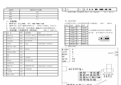
1. RS485通迅,最远1200m . 体积:70mm ×90mm ×24mm
2. AC24V 供电,适用于AC24V 的球形云台 . 可控制三可变镜头、全向云台。
3. 内置10W 开关模块电源,可提供DC12V /500mA 稳压电源给摄像机供电 .
五:接线示意图:
六. 连接示意图:
解码板采用RS485通讯方式的,“A”和“B”为信号接线端,“GND”为屏蔽地,且“A”接RS485设备接口的正端,“B”接RS485设备接口的负端。
6、注意事项:
使用前选择好协议,波特率,解码器地址, 新设置的协议和波特率要重新关断电源5秒再起动后才有效。
协议选择不对、波特率设置不对、485-A、B线极性不对、都将使解码器无法通信。
SA-DV使用说明书
(通用型解码板)
七寸及七寸以上球罩适用
本解码板工作电压为交流24V,千万不可将其直接接入220V 交流市电,切记!!!。
200米无线模块+单片机

模块的资料原理说明:AU-YK04解码接收模块产品型号:AU-YK04 产品名称:5伏高频超再生四路解码接收模块一、技术参数工作电压(V):DC5V静态电流(mA):4.5MA调制方式:调幅(OOK)工作温度: -10℃~ 70℃接收灵敏度(dBm):-105DB工作频率(MHz):315、433.92MHz(266-433MHZ频率段可任选)编码方式:焊盘编码(固定码)工作方式:M4(点动:按住不松手就输出,一松手就停止输出)、L4(互锁:四路同时只能有一路输出)、T4(自锁:四路相互独立输出、互不影响,按一下输出再按一下停止输出)尺寸(LWH):40*22*7mm二、产品特点:超再生接收模块采用LC振荡电路,内含放大整形,输出的数据信号为解码后的高电平信号,使用极为方便,并且价格低廉,所以被广泛使用。
带四路解码输出(同时也可改为六路点动或互锁输出),使用方便;频点调试容易,供货周期短;产品质量一致性好,性价比高。
接收模块有较宽的接收带宽,一般为±10MHz,出厂时一般调在315MHz或433.92MHZ(如有特殊要求可调整频率,频率的调整范围为266MHz~433MHz。
)。
接收模块一般采用DC5V 供电,如有特殊要求可调整电压范围。
三、脚位及使用说明:脚位名称功能说明1VT输出状态指示2D3数据输出3D2数据输出4D1数据输出5D0数据输出65V电源正极 7GND 电源负极8ANT接天线端接收模块一共有八个外部接口,上面有英文表示。
5V 表示接电源正极, D0、D1、D2、D3 表示输出, GND 表示接电源负极, ANT 表示接天线端。
使用前要接上50欧姆1/4波长的天线,并且天线应该是直的,以达到最佳的接收效果,波长=光速/频率。
四、应用环境(应用领域)无线遥控开关、遥控插座、数据传输、遥控玩具、防盗报警主机、车库门、卷闸门、道闸门、伸缩门等门控业及其遥控音响领域等。
五、自选配件与公司发射系列、遥控器系列产品配套使用。
泰科4100U和4010操作面板说明

Controller Board Display Adjustments (显示亮度调整)
• Left-hand single turn potentiometer adjusts display contrast and viewing angle • Right-hand single turn pot dims the back light. • These pots are set at factory, and should only need ‘fiddlin’ under special applications (Hi-Temp, extreme viewing angle)
高级操作键
• • • •
选项
功能
禁止 激活
退出 清除
进入
向前
向后
选项屏驱动英语(或外国)语言提示 双行80字符显示屏对离散系统状况给予清晰显示 40 字符 定制 字幕提供具体的方位讯息 先进的用户键提供操作员如下的访问权限: - 系统登录/退出 @ 通行密码级别 - 检查控制盘或电路讯息 - 检查历史数据记录 - 禁止/激活及其他服务和编程功能
Add-on Memory board(扩展内存) - 6Mbytes FLASH memory
• Standard - Included with NDU
LED/Keypad Board
• Mounts LEDs in all configurations (standard & international keypads) • Mates with rubber matte to complete each key switch for rubber keypad
接线盒
硅奥蓝牙透传模块规格书
硅奥科技蓝牙透传模块蓝牙透传模组功能规格书变更记录目录硅奥科技透传模块项目 (2)透传模组功能规格书 (2)1.产品概述 (6)2.应用领域 (6)3.硬件尺寸图 (7)4.pin脚定义 (7)5.电气特性 (8)6.功耗 (10)7.射频特性 (10)8.AT指令集说明 (12)8.1查询3.0蓝牙地址 (12)8.2查询4.0蓝牙地址: (12)8.3查询3.0蓝牙名字: (12)8.4查询4.0蓝牙名字: (13)8.5查询配对码: (13)8.6 查询版本号: (13)8.7查询设备类型: (13)8.8查询蓝牙设备列表(最多支持4个): (14)8.9查询sniff参数: (14)8.10查询最近使用的认证设备: (14)8.11查询蓝牙模块状态: (14)8.12查询rssi: (15)8.13查询已连接设备: (15)8.14查询附近设备: (15)8.15 查询附近LE设备: (16)8.16设置波特率(全波特率): (16)8.17 设置3.0地址: (16)8.18 设置4.0地址: (16)8.19 设置3.0名字: (17)8.20 设置4.0名字: (17)8.21 设置配对码: (17)8.22 设置设备类型: (17)8.23 设置sniff参数: (18)8.24设置设备列表(删): (18)8.25 设置当前工作模式及指定设备: (18)8.26设置当前工作模式: (18)8.27 重置状态: (19)8.28 重连: (19)8.29断开连接: (19)8.30连接(CMODE时): (19)8.31 sniff动作: (19)8.32 可发现模式: (20)8.33 深度休眠:(未引入) (20)1.产品概述GA-DM-1000模组是支持蓝牙4.0标准协议的模组,同时支持BT3.0 Classic模式以及BLE 模式,该模块基于蓝牙单芯片,遵循BT4.0蓝牙规范。
CRIO-4010 单相、三相全参数交流 电量采集模块 用户手册说明书
CRIO-4010单相、三相全参数交流电量采集模块用户手册版本号:Q7-30-02修订日期:2016-11-1国控精仪(北京)科技有限公司2016年版权所有本软件文档及相关套件均属国控精仪(北京)科技有限公司所有,包含专利信息,其知识产权受国家法律保护,除非本公司书面授权许可,其他公司、组织不得非法使用和拷贝。
为提高产品的性能、可靠性,本文档中的信息如有完善或修改,恕不另行通知,客户可从公司网站下载或致电我们通过电子邮件索取,制造商无需作成承诺和承担责任。
客户使用产品和软件文档进行设备调试和生产时,应进行可靠性、功能性等全面测试,方可进行整体设备的运行或交付。
我们提供7*24电话技术支持服务,及时解答客户问题。
如何从国控精仪获得技术服务我们将为客户提供满意全面的技术服务。
请您通过以下信息联系我们。
国控精仪公司信息网址: 英文中文销售服务: **************销售分机:801 电话: 400 9936 400 ************传真: ************地址: 北京市海淀区安宁庄东路18号2号办公楼420-423室请将您下列的信息通过邮件或传真发送给我们1概述...................................................................................................................................... - 1 -1.1产品特性.................................................................................................................. - 1 -1.2产品应用.................................................................................................................. - 1 -1.3产品详细指标.......................................................................................................... - 2 -1.3.1电量参数...................................................................................................... - 2 -1.3.2系统稳定时间.............................................................................................. - 2 -1.3.3物理特征...................................................................................................... - 3 -1.3.4产品功耗(典型值) ..................................................................................... - 3 -1.3.5工作环境...................................................................................................... - 3 -1.3.6存储环境...................................................................................................... - 3 -1.4软件支持.................................................................................................................. - 3 -2设备安装.............................................................................................................................. - 5 -2.1产品开箱.................................................................................................................. - 5 -2.2软件安装.................................................................................................................. - 5 -2.3产品布局图.............................................................................................................. - 6 -3信号连接说明...................................................................................................................... - 7 -3.1连接器管脚分配...................................................................................................... - 7 -3.2电源与通讯连接...................................................................................................... - 8 -3.3信号连接.................................................................................................................. - 9 -4 模拟量输入(AI)模块功能码........................................................................................ - 10 -4.1读保持寄存器........................................................................................................ - 10 -4.2读输入寄存器........................................................................................................ - 11 -4.3设置单个保持寄存器............................................................................................ - 13 -4.4设置多个保持寄存器............................................................................................ - 13 -5产品注意事项、保修、校准............................................................................................ - 15 -图2-1 CRIO4010产品图................................................................................................... - 6 -图3-1 电源与通讯接线图 ................................................................................................ - 8 -图3-2 单相电示意图 ........................................................................................................ - 9 -图3-3 三相电示意图 ........................................................................................................ - 9 -表3-1 16P端子标注 .......................................................................................................... - 8 -1概述CRIO-4010是基于RS485的高性能通信模块。
AU-YK401C说明书(24伏直流电机正反转控制器)

AU-YK401C说明书一、功能特点:1、两路带电输出,带双限位功能。
2、主要应用于:电机正转反转、遥控电动门(卷闸门上下滑动)、遥控窗帘左右滑动、遥控电机上下升降、安防等遥控领域。
3、采用大容量继电器,可控制上千瓦的电机及设备。
4、采用无线编码技术,无方向性,开关互不干扰。
二、主要技术指标:工作电压DC24V 接收频率315MHZ~433MHZ接收灵敏度-95db 工作方式点动,互锁,自锁最大负载7A三、接线图:限位开关四、操作说明1)按接线图给控制板供DC24V的电源。
输出方式有:点动/自锁/互锁三种方式,输出方式可根据需要随时更改。
2)用互锁方式控制电动机正反转时,如需用限位控制,可断开控制板上KC1 与KC2 的连接线,接入一组常闭辅助触点的行程开关,可实现到位停止功能。
3)输出方式选择及学习方法:按下遥控器的任一键,学习指示灯应连续闪烁,否则本模块不能学习此遥控器。
(点动和自锁方式要求遥控器至少为两键的,互锁方式要求遥控器至少三键)4)输出方式的选择:长按本控制板学习键,大约2秒钟后,学习指示灯变亮;6秒后,学习指示灯由亮变灭;紧接着指示灯会闪烁1次,2次和3次。
在指示灯闪烁一次之后,两次之前,松开学习键,则输出为点动方式;在指示灯闪烁两次之后,三次之前,松开学习键,则输出为自锁方式;在指示灯闪烁三次后,松开学习键,则输出为互锁方式。
5)学习方法:再选定输出方式之后,长按本控制板学习键,直到灯亮松开,交替按按遥控器上需要控制的两个按键,学习指示灯闪烁三次之后变亮,表示学习成功。
如需增加遥控器数量控制时,只需重复斜体字部份的内容即可。
最多能学习十六个不同编码的遥控器,第十七次将覆盖第一次记忆的遥控器。
(互锁方式除已学习的两键外,另外任一键为停止键)6)清零:长按学习键,指示灯由亮变灭,松开即可清零。
- 1、下载文档前请自行甄别文档内容的完整性,平台不提供额外的编辑、内容补充、找答案等附加服务。
- 2、"仅部分预览"的文档,不可在线预览部分如存在完整性等问题,可反馈申请退款(可完整预览的文档不适用该条件!)。
- 3、如文档侵犯您的权益,请联系客服反馈,我们会尽快为您处理(人工客服工作时间:9:00-18:30)。
AU-YK04解码接收模块规格说明书
产品型号:AU-YK04
产品名称:5伏高频超再生四路解码接收模块
一、技术参数
工作电压(V):DC5V
静态电流(mA): 4.5MA
调制方式:调幅(OOK)
工作温度: -10℃~+70℃
接收灵敏度(dBm):-105DB
工作频率(MHz):315、433.92MHz(266-433MHZ频率段可任选)
编码方式:焊盘编码(固定码)
工作方式:M4(点动:按住不松手就输出,一松手就停止输出)、L4(互锁:四路同时只能有一路输出)、T4(自锁:四路相互独立输出、互不影响,按一下输出再按一下停止输出)
尺寸(LWH):40*22*7mm
二、产品特点:
超再生接收模块采用LC振荡电路,内含放大整形,输出的数据信号为解码后的高电平信号,使用极为方便,并且价格低廉,所以被广泛使用。
带四路解码输出(同时也可改为六路点动或互锁输出),使用方便;频点调试容易,供货周期短;产品质量一致性好,性价比高。
接收模块有较宽的接收带宽,一般为±10MHz,出厂时一般调在315MHz或433.92MHZ(如有特殊要求可调整频率,频率的调整范围为266MHz~433MHz。
)。
接收模块一般采用DC5V供电,如有特殊要求可调整电压范围。
三、脚位及使用说明:
接收模块一共有八个外部接口,上面有英文表示。
“5V”表示接电源正极,“ D0、D1、D2、D3”表示输出,“GND”表示接电源负极,“ANT”表示接天线端。
使用前要接上50欧姆1/4波长的天线,并且天线应该是直的,以达到最佳的接收效果,波长=光速/频率。
四、应用环境(应用领域)
无线遥控开关、遥控插座、数据传输、遥控玩具、防盗报警主机、车库门、卷闸门、道闸门、伸缩门等门控业及其遥控音响领域等。
五、自选配件
与公司发射系列、遥控器系列产品配套使用。
六、备注
VCC电压要与模块工作电压一致,且要做好电源滤波;
天线对模块的接收效果影响很大,最好接1/4波长的天线,一般采用50欧姆单芯导线,天线的长度315M的约为23cm,433M的约为17cm;
天线位置对模块接收效果亦有影响,安装时,天线尽可能伸直,远离屏蔽体,高压,及干扰源的地方;
使用时接收频率、解码方式应与发射匹配。