外文翻译--制袋机控制系统研究
外文翻译---机械手的机械和控制系统
机械手的机械和控制系统文章来源:Dirk Osswald, Heinz Wörn.Department of Computer Science , Institute for Process Control and Robotics (IPR).,Engler-Bunte-Ring 8 - Building 40.28.摘要:最近,全球内带有多指夹子或手的机械人系统已经发展起来了,多种方法应用其上,有拟人化的和非拟人化的。
不仅调查了这些系统的机械结构,而且还包括其必要的控制系统。
如同人手一样,这些机械人系统可以用它们的手去抓不同的物体,而不用改换夹子。
这些机械手具备特殊的运动能力(比如小质量和小惯性),这使被抓物体在机械手的工作范围内做更复杂、更精确的操作变得可能。
这些复杂的操作被抓物体绕任意角度和轴旋转。
本文概述了这种机械手的一般设计方法,同时给出了此类机械手的一个示例,如卡尔斯鲁厄灵巧手Ⅱ。
本文末介绍了一些新的构想,如利用液体驱动器为类人型机器人设计一个全新的机械手。
关键词:多指机械手;机器人手;精操作;机械系统;控制系统1.引言2001年6月在德国卡尔斯鲁厄开展的“人形机器人”特别研究,是为了开发在正常环境(如厨房或客厅)下能够和人类合作和互动的机器人系统。
设计这些机器人系统是为了能够在非专业、非工业的条件下(如身处多物之中),帮我们抓取不同尺寸、形状和重量的物体。
同时,它们必须能够很好的操纵被抓物体。
这种极强的灵活性只能通过一个适应性极强的机械人手抓系统来获得,即所谓的多指机械手或机器人手。
上文提到的研究项目,就是要制造一个人形机器人,此机器人将装备这种机器人手系统。
这个新手将由两个机构合作制造,它们是卡尔斯鲁厄大学的IPR(过程控制和机器人技术研究院)和c(计算机应用科学研究院)。
这两个组织都有制造此种系统的相关经验,但是稍有不同的观点。
IPR制造的卡尔斯鲁厄灵巧手Ⅱ(如图1所示),是一个四指相互独立的手爪,我们将在此文中详细介绍。
外文翻译-基于PLC自动售货机控制系统设计

外文翻译-基于PLC自动售货机控制系统设计As our XXX。
XXX machines。
in particular。
XXX。
XXX optical。
mechanical。
and electrical components in order to n properly。
Furthermore。
vending machines have no space nsXXX.In order to design a vending machine control system that is reliable。
has a wide voltage range。
and is easy to program and maintain。
a PLC-based control system is mended。
This type of control system is ideal for vending machines as it can easily handle the complex tasks required for vending machine n.The PLC-based control system for a vending machine should include monitoring and control of all the machine's components。
including the power supply。
sensors。
motors。
XXX。
it should be able to handle real-time data processing and XXX external systems。
XXX.In terms of programming。
the PLC-based control system should be designed to be user-friendly and easy to modify as needed。
制袋机控制系统研究

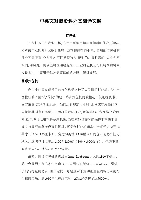
制 袋 过 程 的 工 艺 流 程 图 如 下 图 1所 示 :
动 以 纠 正 塑 料 膜 。 纠 偏 控 制 器 可 由 工 控 机 取 代 , 过 A 和 D 板 卡 通 D A 来 采 集 偏 差 信 号 和 控 制 纠 偏 伺 服 机 构 。 利 用 工 控 机 的 软 件 资 源 可 以 设 计 出 非 常 友 好 的人 机 界 面 , 是 传 统 光 电 纠 偏 控 制 器 所 无 法 完 成 的 。 这
图 1 工 艺 流 程 图
电纠 偏 控 制 , 目前 张 力 控制 多 数 由独 立 的 张 力 控 制 系过 程 中 。 膜 卷 材 续 展 开 , 通 过 光 电 纠 偏 和 进 给 机 要 包 括 张 力 控 制 器 、 力 检 测 器 、 力 表 、 合 器 及 制 动 器 。 全 自 动 薄 并 张 张 离 构 源 源 不 断 地 进 入 折 叠 成 型 装 置 中 的 。 薄 膜 经 过 折 叠 成 型 后 , 定 张 力 控 制 是 有 张 力 检 测 器 来 直 接 测 定 卷 料 的 张 力 . 后 把 张 力 数 据 由 然 长 定 位 牵 引 装 置 进 行 牵 引 和 定 位 进 入 热 封 工 序 。制 袋 流 程 中 的 热 封 变 成 张 力 信 号 传 回 张 力 控 制 器 , 力 控 制 器 来 调 整 离 合 器 或 制 动 器 张
打包机论文中英文对照资料外文翻译文献
中英文对照资料外文翻译文献打包机打包机是一种农业机械,它用于压缩已切割和倾斜的作物(如草、稻草或青贮饲料)成易于处理、运输和储存的小包。
常用的打包机有几个不同类型,分别生产不同类型的包-矩形的、圆柱形的,大小各不相同,用麻绳、网或金属丝缠绕起来。
工业打包机还可以用在材料回收设备上,主要用于包装需要运输的金属、塑料或纸。
圆形打包机在工业化国家最常用的打包机是这种又大又圆的打包机。
它生产圆柱状的“圆”或“筒状”的包。
草在打包机内被捲起,使用橡胶带、固定滚筒,或两者的组合。
当包达到规定尺寸时,用网或麻绳裹住它,以保持其固有的形状。
打包机的后面打开,包被排出。
包在这个阶段完成,但也可以用塑料薄膜包裹,当在室外储存时能保持干草的干燥或者将潮湿的草变成青贮饲料。
可变仓打包机通常生产直径为48至72英寸(120~ 180厘米)、宽达60英寸(150厘米)的包。
无论在任何地区,这些包可以重达1100至2200磅(500-1000公斤),包的重量取决于大小,材料,和水分含量。
最初,圆形打包机的构思由Ummo Luebbens于大约1910年提出,第一台圆形打包机才生产出来,一直到1947年Allis-Chalmers 引进了旋转打包机之后。
由于它的干草包脱水干燥和重量轻的特点从而得以推向市场,到1960年生产结束时,AC已经销售了近70000台接下来的一个重大创新是在1972年,当时Vermeer公司开始出售其型号为605的第一台现代圆形打包机。
以前,圆的干草包仅仅是干草缚在一起的肿块,但Vermeer设计使用皮带将干草紧密结合起来形成一个圆柱体,正如今天所看到的样子。
大型矩形打包机另一种常用类型的打包机生产大型的矩形包,每个包缠绕半打左右的麻绳,然后再打结。
这样的包非常紧凑,重量又普遍比圆形的包大几分。
在加拿大的草原,它们被称为草原猛禽。
小型矩形打包机这种打包机现今是不常见的,但在许多国家却是相当流行,如新西兰和澳大利亚,除了大型包的生产,还生产小型矩形 (通常被称为“正方形的”) 包。
新型多制式高速制袋机控制系统研发

背心袋制袋机的原理与维修的书

背心袋制袋机的原理与维修的书英文回答:The principle of a vest bag making machine is to take a roll of plastic film, cut it into the desired size, and then seal the edges to form a bag. The machine is equipped with a series of rollers, cutters, and sealing bars that work together to perform these tasks. The plastic film is fed through the machine and passed over the rollers, which help to guide the film and keep it in position. The cutters then cut the film to the required length, and the sealing bars heat-seal the edges to create the bags.To maintain and repair a vest bag making machine, it is important to regularly inspect and clean the various components. The rollers should be checked for any signs of wear or damage, and the cutters and sealing bars should be inspected for proper alignment and functionality. Any worn or damaged parts should be replaced to ensure the machine continues to operate effectively.Regular lubrication of moving parts is also essentialto prevent excessive wear and ensure smooth operation. Additionally, the electrical components of the machine should be inspected for any loose connections or signs of overheating. Proper maintenance and timely repairs are crucial for maximizing the lifespan and performance of avest bag making machine.中文回答:背心袋制袋机的原理是将一卷塑料薄膜切割成所需尺寸,然后封口边缘以形成袋子。
阀口袋包装机的一种改进控制系统
阀口袋包装机的一种改进控制系统An Improved Control System of the Air Valve Packer居上江 阙沛文(上海交通大学自动检测研究所,上海 200030)摘 要分析了以51系列单片机为核心的阀口袋包装机的控制系统,该控制系统为了适应包装物料特性的变化,提出了一种改进的方案。
该方案利用下游重量校准反馈并运用模糊控制过程,使包装速度和精度都有了一定的提高。
关键词阀口袋包装机测量误差自适应控制Abstract This paper analyses the 51 series single-chip microprocessor based control system for the air valve packer. In order to adapt to the change of the material characteristic, an improved control system is presented. The control system improves the packing velocity and precision to a certain extent by feeding back from downstream weigh calibration and applying fuzzy control process.Keywords Air valve packer Measurement error Adaptive control0 引言阀口袋包装机是为适应颗粒、粉粒混合物及片状物料而专门设计的毛重式包装机型。
该机采用低压空气强制压送物料装袋,成功地解决了自流性差、密度小、微粒度等特性的粉末物料的自动计量包装,结构新颖合理,操作维护方便,在化工行业有较广泛的应用。
1 阀口袋包装机系统及其误差分析阀口袋包装机由进料闸板阀、储料仓、物料充填装置(气动双速阀门控制)、机架、回风除尘装置、称量、翻袋装置以及称重控制柜等组成。
机械类 数控 外文翻译 外文文献 英文文献 PID控制器
PID controllerA proportional–integral–derivative controller (PID controller) is a generic .control loop feedback mechanism widely used in industrial control systems. A PID controller attempts to correct the error between a measured process variable and a desired setpoint by calculating and then outputting a corrective action that can adjust the process accordingly.The PID controller calculation (algorithm) involves three separate parameters; the Proportional, the Integral and Derivative values. The Proportional value determines the reaction to the current error, the Integral determines the reaction based on the sum of recent errors and the Derivative determines the reaction to the rate at which the error has been changing. The weightedsum of these three actions is used to adjust the process via a control element such as the position of a control valve or the power supply of a heating element.By "tuning" the three constants in the PID controller algorithm the PID can provide control action designed for specific process requirements. The response of the controller can be described in terms of the responsiveness of the controller to an error, the degree to which the controller overshoots the setpoint and the degree of system oscillation. Note that the use of the PID algorithm for control does not guarantee optimal control of the system or system stability.Some applications may require using only one or two modes to provide the appropriate system control. This is achieved by setting the gain of undesired control outputs to zero. A PID controller will be called a PI, PD, P or I controller in the absence of the respective control actions. PI controllers are particularly common, since derivative action is very sensitive to measurement noise, and the absence of an integral value may prevent the system from reaching its target value due to the control action.Note: Due to the diversity of the field of control theory and application, many naming conventions for the relevant variables are in common use.1.Control loop basicsA familiar example of a control loop is the action taken to keep one's shower water at the ideal temperature, which typically involves the mixing of two process streams, cold and hot water. The person feels the water to estimate its temperature. Based on this measurement they perform a control action: use the cold water tap to adjust the process. The person would repeat this input-output control loop, adjusting the hot water flow until the process temperature stabilized at the desired value.Feeling the water temperature is taking a measurement of the process value or process variable (PV). The desired temperature is called the setpoint (SP). The output from the controller and input to the process (the tap position) is called the manipulated variable (MV). The difference between the measurement and the setpoint is the error (e), too hot or too cold and by how much.As a controller, one decides roughly how much to change the tap position (MV) after one determines the temperature (PV), and therefore the error. This first estimate is the equivalent of the proportional action of a PID controller. The integral action of a PID controller can be thought of as gradually adjusting the temperature when it is almost right. Derivative action can be thought of as noticing the water temperature is getting hotter or colder, and how fast, and taking that into account when deciding how to adjust the tap.Making a change that is too large when the error is small is equivalent to a high gain controller and will lead to overshoot. If the controller were to repeatedly make changes that were too large and repeatedly overshoot the target, this control loop would be termed unstable and the output would oscillate around the setpoint in either a constant, growing, or decaying sinusoid. A human would not do this because we are adaptive controllers, learning from the process history, but PID controllers do not have the ability to learn and must be set up correctly. Selectingthe correct gains for effective control is known as tuning the controller.If a controller starts from a stable state at zero error (PV = SP), then further changes by the controller will be in response to changes in other measured or unmeasured inputs to the process that impact on the process, and hence on the PV. Variables that impact on the process other than the MV are known as disturbances and generally controllers are used to reject disturbances and/or implement setpoint changes. Changes in feed water temperature constitute a disturbance to the shower process.In theory, a controller can be used to control any process which has a measurable output (PV), a known ideal value for that output (SP) and an input to the process (MV) that will affect the relevant PV. Controllers are used in industry to regulate temperature, pressure, flow rate, chemical composition, speed and practically every other variable for which a measurement exists. Automobile cruise control is an example of a process which utilizes automated control.Due to their long history, simplicity, well grounded theory and simple setup and maintenance requirements, PID controllers are the controllers of choice for many of these applications.2.PID controller theoryNote: This section describes the ideal parallel or non-interacting form of the PID controller. For other forms please see the Section "Alternative notation and PID forms".The PID control scheme is named after its three correcting terms, whose sum constitutes the manipulated variable (MV). Hence:where Pout, Iout, and Dout are the contributions to the output from the PID controller from each of the three terms, as defined below.2.1. Proportional termThe proportional term makes a change to the output that is proportional to the current error value. The proportional response can be adjusted by multiplying the error by a constant Kp, called the proportional gain.The proportional term is given by:WherePout: Proportional outputKp: Proportional Gain, a tuning parametere: Error = SP − PVt: Time or instantaneous time (the present)Change of response for varying KpA high proportional gain results in a large change in the output for a given change in the error. If the proportional gain is too high, the system can become unstable (See the section on Loop Tuning). In contrast, a small gain results in a small output response to a large input error, and a less responsive (or sensitive) controller. If the proportional gain is too low, the control action may be too small when responding to system disturbances.In the absence of disturbances, pure proportional control will not settle at its target value, but will retain a steady state error that is a function of the proportional gain and the process gain. Despite the steady-state offset, both tuning theory and industrial practice indicate that it is the proportional term that should contribute the bulk of the output change.2.2.Integral termThe contribution from the integral term is proportional to both the magnitude of the error and the duration of the error. Summing the instantaneous error over time (integrating the error) gives the accumulated offset that should have been corrected previously. The accumulated error is then multiplied by the integral gain and added to the controller output. The magnitude of the contribution of the integral term to the overall control action is determined by the integral gain, Ki.The integral term is given by:Iout: Integral outputKi: Integral Gain, a tuning parametere: Error = SP − PVτ: Time in the past contributing to the integral responseThe integral term (when added to the proportional term) accelerates the movement of the process towards setpoint and eliminates the residual steady-state error that occurs with a proportional only controller. However, since the integral term is responding to accumulated errors from the past, it can cause the present value to overshoot the setpoint value (cross over the setpoint and then create a deviation in the other direction). For further notes regarding integral gain tuning and controller stability, see the section on loop tuning.2.3 Derivative termThe rate of change of the process error is calculated by determining the slope of the error over time (i.e. its first derivative with respect to time) and multiplying this rate of change by the derivative gain Kd. The magnitude of the contribution of the derivative term to the overall control action is termed the derivative gain, Kd.The derivative term is given by:Dout: Derivative outputKd: Derivative Gain, a tuning parametere: Error = SP − PVt: Time or instantaneous time (the present)The derivative term slows the rate of change of the controller output and this effect is most noticeable close to the controller setpoint. Hence, derivative control is used to reduce the magnitude of the overshoot produced by the integral component and improve the combined controller-process stability. However, differentiation of a signal amplifies noise and thus this term in the controller is highly sensitive to noise in the error term, and can cause a process to become unstable if the noise and the derivative gain are sufficiently large.2.4 SummaryThe output from the three terms, the proportional, the integral and the derivative terms are summed to calculate the output of the PID controller. Defining u(t) as the controller output, the final form of the PID algorithm is:and the tuning parameters areKp: Proportional Gain - Larger Kp typically means faster response since thelarger the error, the larger the Proportional term compensation. An excessively large proportional gain will lead to process instability and oscillation.Ki: Integral Gain - Larger Ki implies steady state errors are eliminated quicker. The trade-off is larger overshoot: any negative error integrated during transient response must be integrated away by positive error before we reach steady state.Kd: Derivative Gain - Larger Kd decreases overshoot, but slows down transient response and may lead to instability due to signal noise amplification in the differentiation of the error.3. Loop tuningIf the PID controller parameters (the gains of the proportional, integral and derivative terms) are chosen incorrectly, the controlled process input can be unstable, i.e. its output diverges, with or without oscillation, and is limited only by saturation or mechanical breakage. Tuning a control loop is the adjustment of its control parameters (gain/proportional band, integral gain/reset, derivative gain/rate) to the optimum values for the desired control response.The optimum behavior on a process change or setpoint change varies depending on the application. Some processes must not allow an overshoot of the process variable beyond the setpoint if, for example, this would be unsafe. Other processes must minimize the energy expended in reaching a new setpoint. Generally, stability of response (the reverse of instability) is required and the process must not oscillate for any combination of process conditions and setpoints. Some processes have a degree of non-linearity and so parameters that work well at full-load conditions don't work when the process is starting up from no-load. This section describes some traditional manual methods for loop tuning.There are several methods for tuning a PID loop. The most effective methods generally involve the development of some form of process model, then choosing P, I, and D based on the dynamic model parameters. Manual tuning methods can be relatively inefficient.The choice of method will depend largely on whether or not the loop can be taken "offline" for tuning, and the response time of the system. If the system can be taken offline, the best tuning method often involves subjecting the system to a step change in input, measuring the output as a function of time, and using this response to determine the control parameters.Choosing a Tuning MethodMethodAdvantagesDisadvantagesManual TuningNo math required. Online method.Requires experiencedpersonnel.Ziegler–NicholsProven Method. Online method.Process upset, sometrial-and-error, very aggressive tuning.Software ToolsConsistent tuning. Online or offline method. May includevalve and sensor analysis. Allow simulation before downloading.Some costand training involved.Cohen-CoonGood process models.Some math. Offline method. Only good forfirst-order processes.3.1 Manual tuningIf the system must remain online, one tuning method is to first set the I and D values to zero. Increase the P until the output of the loop oscillates, then the P should be left set to be approximately half of that value for a "quarter amplitude decay" type response. Then increase D until any offset is correct in sufficienttime for the process. However, too much D will cause instability. Finally, increase I, if required, until the loop is acceptably quick to reach its reference after a load disturbance. However, too much I will cause excessive response and overshoot. A fast PID loop tuning usually overshoots slightly to reach the setpoint more quickly; however, some systems cannot accept overshoot, in which case an "over-damped" closed-loop system is required, which will require a P setting significantly less than half that of the P setting causing oscillation.3.2Ziegler–Nichols methodAnother tuning method is formally known as the Ziegler–Nichols method, introduced by John G. Ziegler and Nathaniel B. Nichols. As in the method above, the I and D gains are first set to zero. The "P" gain is increased until it reaches the "critical gain" Kc at which the output of the loop starts to oscillate. Kc and the oscillation period Pc are used to set the gains as shown:3.3 PID tuning softwareMost modern industrial facilities no longer tune loops using the manual calculation methods shown above. Instead, PID tuning and loop optimization software are used to ensure consistent results. These software packages will gather the data, develop process models, and suggest optimal tuning. Some software packages can even develop tuning by gathering data from reference changes.Mathematical PID loop tuning induces an impulse in the system, and then uses the controlled system's frequency response to design the PID loop values. In loops with response times of several minutes, mathematical loop tuning is recommended, because trial and error can literally take days just to find a stable set of loop values. Optimal values are harder to find. Some digital loop controllers offer a self-tuning feature in which very small setpoint changes are sent to the process, allowing the controller itself to calculate optimal tuning values.Other formulas are available to tune the loop according to different performance criteria.4 Modifications to the PID algorithmThe basic PID algorithm presents some challenges in control applications that have been addressed by minor modifications to the PID form.One common problem resulting from the ideal PID implementations is integralwindup. This can be addressed by:Initializing the controller integral to a desired valueDisabling the integral function until the PV has entered the controllable regionLimiting the time period over which the integral error is calculatedPreventing the integral term from accumulating above or below pre-determined boundsMany PID loops control a mechanical device (for example, a valve). Mechanical maintenance can be a major cost and wear leads to control degradation in the form of either stiction or a deadband in the mechanical response to an input signal. The rate of mechanical wear is mainly a function of how often a device is activated to make a change. Where wear is a significant concern, the PID loop may have an output deadband to reduce the frequency of activation of the output (valve). This is accomplished by modifying the controller to hold its output steady if the change would be small (within the defined deadband range). The calculated output must leave the deadband before the actual output will change.The proportional and derivative terms can produce excessive movement in the output when a system is subjected to an instantaneous "step" increase in the error, such as a large setpoint change. In the case of the derivative term, this is due to taking the derivative of the error, which is very large in the case of an instantaneous step change.5. Limitations of PID controlWhile PID controllers are applicable to many control problems, they can perform poorly in some applications.PID controllers, when used alone, can give poor performance when the PID loop gains must be reduced so that the control system does not overshoot, oscillate or "hunt" about the control setpoint value. The control system performance can be improved by combining the feedback (or closed-loop) control of a PID controller with feed-forward (or open-loop) control. Knowledge about the system (such as the desired acceleration and inertia) can be "fed forward" and combined with the PID output to improve the overall system performance. The feed-forward value alone can often provide the major portion of the controller output. The PID controller can then be used primarily to respond to whatever difference or "error" remains between the setpoint (SP) and the actual value of the process variable (PV). Since the feed-forward output is not affected by the process feedback, it can never cause the control system to oscillate, thus improving the system response and stability.For example, in most motion control systems, in order to accelerate a mechanical load under control, more force or torque is required from the prime mover, motor, or actuator. If a velocity loop PID controller is being used to control the speed of the load and command the force or torque being applied by the prime mover, then it is beneficial to take the instantaneous acceleration desired for the load, scale that value appropriately and add it to the output of the PID velocity loop controller. This means that whenever the load is being accelerated or decelerated, a proportional amount of force is commanded from the prime mover regardless of the feedback value. The PID loop in this situation uses the feedback information to effect any increase or decrease of the combined output in order to reduce the remaining difference between the process setpoint and thefeedback value. Working together, the combined open-loop feed-forward controller and closed-loop PID controller can provide a more responsive, stable and reliable control system.Another problem faced with PID controllers is that they are linear. Thus, performance of PID controllers in non-linear systems (such as HV AC systems) is variable. Often PID controllers are enhanced through methods such as PID gain scheduling or fuzzy logic. Further practical application issues can arise from instrumentation connected to the controller. A high enough sampling rate, measurement precision, and measurement accuracy are required to achieve adequate control performance.A problem with the Derivative term is that small amounts of measurement or process noise can cause large amounts of change in the output. It is often helpful to filter the measurements with a low-pass filter in order to remove higher-frequency noise components. However, low-pass filtering and derivative control can cancel each other out, so reducing noise by instrumentation means is a much better choice. Alternatively, the differential band can be turned off in many systems with little loss of control. This is equivalent to using the PID controller as a PI controller.6. Cascade controlOne distinctive advantage of PID controllers is that two PID controllers can be used together to yield better dynamic performance. This is called cascaded PID control. In cascade control there are two PIDs arranged with one PID controlling the set point of another. A PID controller acts as outer loop controller, which controls the primary physical parameter, such as fluid level or velocity. The other controller acts as inner loop controller, which reads the output of outer loop controller as set point, usually controlling a more rapid changing parameter, flowrate or accelleration. It can be mathematically proved that the working frequency of the controller is increased and the time constant of the object is reduced by using cascaded PID controller.[vague]7. Physical implementation of PID controlIn the early history of automatic process control the PID controller was implemented as a mechanical device. These mechanical controllers used a lever, spring and a mass and were often energized by compressed air. These pneumatic controllers were once the industry standard.Electronic analog controllers can be made from a solid-state or tube amplifier, a capacitor and a resistance. Electronic analog PID control loops were often found within more complex electronic systems, for example, the head positioning of a disk drive, the power conditioning of a power supply, or even the movement-detection circuit of a modern seismometer. Nowadays, electronic controllers have largely been replaced by digital controllers implemented with microcontrollers or FPGAs.Most modern PID controllers in industry are implemented in software in programmable logic controllers (PLCs) or as a panel-mounted digital controller. Software implementations have the advantages that they are relatively cheap and are flexible with respect to the implementation of the PID algorithm.PID控制器比例积分微分控制器(PID调节器)是一个控制环,广泛地应用于工业控制系统里的反馈机制。
自动包装机外文翻译文献
自动包装机外文翻译文献(文档含中英文对照即英文原文和中文翻译)译文:药物的自动包装装置1.发明的技术领域最新的发明是一个药物包装仪器。
它能在每次使用的时候单独给予药物包装。
就好像医院和药房等使用的用于药片包装,粉末状药物包装的仪器。
更特别的是这个仪器拥有区分同一药品货架上的储存类药品:如药片,胶囊。
2. 背景技术的描述众所周知,传统的药物包装装置以种类为基础进行药品分类,并将药物吸纳在药剂容器中而且任何一个多元化的货架都与每个容器的药物有关。
这种类型的药物包装装置,根据每个货架的货架号,将所需的药物从相应的药剂容器中取出,并进行包装。
例如,日本已审核专利号1-14081公开的一种药物的自动包装装置,在该装置中的代码都被分配给各自的药剂容器,并通过操作装置上的一个操作键,将所需的药物放在预定的位置进行选择。
日本已审核专利号3-41208公开了一种片剂的供给装置,根据装置中每片的识别信息来确定位置信息,指定所需的片馈线和相应的片剂供给。
日本已审核专利号2-933837公开了一种药剂包装装置,一旦安装药剂容器,装置将读取它的医药数据并存储它的链接地址。
所以,根据每个药物的链接地址,可以达到所需的药物供应和包装的目的。
然而,在上述传统的药物包装装置中,尚未充分考虑在交换药物容器上的可操作性。
换句话说,虽然每个药物的本身的信息是很重要的,但通过使用维护屏幕会改变药物货架编号,当然它是不可能直接改变每个货架号码和相应的药剂的匹配的。
在实际情况下,作为一名药剂师,需要知道每一个架子和相应的药物之间的对应关系,而这严重的加强了操作者的负担。
此外,操作维护屏幕也是复杂的,而且往往会造成输入的错误,其结果是导致药剂师的药物的配给和包装过程变得困难。
此外,它也使药剂师难以精确地操作从相应的货架上安装或者拆卸一个药剂容器这一过程。
正式因为如此,才更需要一个能区分出现在一个区域内药物的药物包装装置,以此来说明哪些药物是附属的,哪些药物是单独使用的。
中英文文献-高速全自动包装机plc控制系统设计
1可编程逻辑控制器1.1简介控制工程已经发展了时间。
在过去的人类是一种用于控制系统的主要方法。
更多最近的电力已经被用于控制和早期的电气控制是基于继电器。
这些继电器使权力被打开和关闭开关没有机械开关。
它是通常使用的继电器,使简单的逻辑控制决策。
低成本计算机的发展带来了最新的革命,可编程逻辑控制器(PLC)。
PLC 的出现始于20世纪70年代,并已成为生产控制最常见的选择。
PLC已获得在工厂车间普及,将可能继续主导一段时间的到来。
大部分的这是因为它们提供的优点。
成本有效控制复杂的系统。
灵活的可以重新应用到快速,轻松地控制其他系统。
计算能力允许更复杂的控制。
故障排除辅助工具使编程更容易,并减少停机时间。
可靠的组件,使这些可能发生故障前几年进行操作。
1.2梯形图梯形逻辑是用于PLC的主要编程方法。
如前面提到的,梯形逻辑已经发展到模仿继电器逻辑。
使用继电器逻辑图的决定是战略之一。
通过选择梯形图作为主要编程方法,培训量所需的工程师和行业的人大大减少。
现代控制系统还包括继电器,但这些很少使用的逻辑。
继电器是一种利用磁场来控制开关,如下图图1.1一个简单的装置。
当电压被施加到输入线圈,所产生的电流产生的磁场。
磁场拉一个金属开关(或簧片)朝它和接触触摸,关闭开关。
该时闭合线圈通电时的接触被称为常开。
常闭触点接触时,输入线圈不通电。
以示意图的形式用一个圆圈来代表输入继电器线圈通常绘制。
输出触点,只显示两条平行线。
常开触点被示为两行,并且将开放(不导通)时,输入不通电。
常闭触点,只显示两行通过其对角线。
当输入线圈不通电时,常闭触点将闭合(导通)。
继电器是用来让一个电源关闭另一个(通常是大电流)电源开关,同时保持他们孤立。
在一个简单的控制应用程序中的继电器的一个例子示于图2.2中。
在这个系统中在左侧的第一继电器被用作常闭的,并且允许电流流动,直到电压被施加到输入端A的第二个继电器为常开,并且不允许电流流过,直到电压被施加到输入B,如果电流流过前两继电器则电流将流过线圈在第三继电器,并关闭输出C.开关该电路通常会在梯形逻辑形式绘制。
- 1、下载文档前请自行甄别文档内容的完整性,平台不提供额外的编辑、内容补充、找答案等附加服务。
- 2、"仅部分预览"的文档,不可在线预览部分如存在完整性等问题,可反馈申请退款(可完整预览的文档不适用该条件!)。
- 3、如文档侵犯您的权益,请联系客服反馈,我们会尽快为您处理(人工客服工作时间:9:00-18:30)。
附录一Bag-making machine control system research The bag-making machine control system is controls based on the labor machine the integration computer control system, controls machine the control software by the labor to complete the system bag process each kind of function coordination control, and substitutes the original mechanical major axis by the electronic axis, had guaranteed strictly each printing unit's synchronization, provides one kind for the bag-making machine based on the computer control integration solution. The bag-making machine is on the processed foods production line manufactures bag's processing equipment using the plastic film.Bag-making machine's control system mainly includes: The main actuation electrical machinery servocontrol, the fixed-length positioning control system, the tensity control system, the temperature control system, to feed control system and the electro-optic correct an error the control system. At present, the most bag-making machine control system's host actuation electrical machinery servocontrol and the fixed-length positioning control system is a body, namely controls take the labor machine forms a three servocontrol as the control core, but the tensity, the electro-optic correct an error, the temperature and to feed control system independence in this three servocontrol. Each system independent types of control increased the bag-making machine coordination control difficulty mutually, also reduced the entire control system's reliability, to further enhance system's automated performance, must develop the new control plan.In the system bag process, the thin film volume material launches continuously, and corrects an error through the electro-optic with the advanced gear to enter in continuously the folding formation installment. Thin film after folding formation, carries on the hauling and the localization by the fixed-length localization draw gear enters the heat-seal working procedure. Makes in the bag flow the heat-seal working procedure, is causes the laminated film heat-seal spot using the heating wire heating the heat-seal level to turn the plastic flow condition, draws support again cutting tool'spressure, causes high and low two heat-seal material each other to fuse together in together, after the cooling, can maintain certain intensity, has leak-proof and so on good. The heat-seal good bag may according to need to carry on processings and so on punch and margin, finally completes the dinking die by the dinking die installment, makes the end product bag.Bag-making machine's control system must complete the main servo electrical machinery and the feed bag hauling servo electrical machinery's motion control, this contained feed bag's fixed-length positioning control, the system must also complete the feed bag to correct an error, to feed, the tensity and the heat-seal temperature control. The control system controls take the labor machine as a core, carries on each control function the hardware expansion, controls machine the control software through the labor to improve each function conformity the system coordination control performance, forms a computer control system. In addition, the remote diagnosis technology applies in the bag-making machine can strengthen bag-making machine's maintainability.The main servo electrical machinery's types of control are the speed control, the main electrical machinery leads the hot knife vertical motion through four pole organizations, through controls the main electrical machinery driver's speed to control hot knife's state of motion. The feed bag hauling servo electrical machinery's control is the position control, must realize the fixed-length localization hauling. These three servo electrical machinery's coordination control can guarantee the hauling and the heat-seal and the dinking die coordinated work. Puts the material and the feed bag to feed servo electrical machinery may unify with this three servo motor control forms a multiple spindle servo to actuate the control system together. The use may complete many servo electrical machinery's motion control based on the PC machine main line's multiple spindle movement controller, like this simplified the servo to actuate control system's hardware, favored each servo electrical machinery's coordination control. The movement controller controls machine the main line through the labor to carry on the communication with it, like this causes employing labor to control machine the control software then to monitor the movement controller, realizes toeach servo electrical machinery's control.Fixed-length, the positioning control must have custom-made in firmly the bag process bag's length, the heat-seal and the dinking die position. The longitudinal localization is refers to the thin film carries on the fixed-length hauling the control, enables the product to have the good uniformity. The longitudinal localization completes by two feed bag hauling servo electrical machinery, the servo electrical machinery must move according to the S shape curve addition and subtraction ship promptly carries on the intermittent type fixed-length localization hauling, guaranteed that the hauling dynamic process is steady. Two servo electrical machinery must maintain the synchronized movements, this may complete the synchronization control through the movement controller. Regarding the synchronization accuracy requirement high situation, may use the torque synthesis feedback form the control policy, realizes two axis couplings. When the accuracy requirement is ordinary, may use the synchronized main reference form the control policy. Two kind of control policy hardware request basic consistent, is only the software complex degree is different.The crosswise localization, namely the electro-optic corrects an error to control, refers to the route which the control plastic membrane walks, enables it not to deviate the fixed track, must overcome so-called “the fishtail” the question. At present is independent the electro-optic to correct an error the equipment to use the photoelectric sensor to examine the plastic membrane boundary, when occurs runs, corrects an error the controller to correct an error the servo to send out the control signal, causes it to lead a material volume movement through the guide screw to correct the plastic membrane. Corrects an error the controller to be possible to control machine the substitution by the labor, gathers the error signal and the control through AD and the DA board card corrects an error the servo. Advantage employing labor controls machine the software resource may design the very friendly man-machine contact surface, this is the traditional electro-optic corrects an error the controller to be unable to complete.The plastic membrane is one flexible material, will have the stretch elongationunder certain temperature and the tensity, both will cause thickness to be uneven, and will have the bulging, will affect the product the quality. The tensity control's quality has the material effect to the product quality, when complete machine movement in high speed is especially obvious. The tensity control mainly exists in putting between the material and to feed and two carry-over pinch rolls. Is similar corrects an error with the electro-optic to control, at present the tensity control completes most by the independent tensity control system, mainly includes the tensity controller, the tensity detector, the tensiometer, the coupling and the brake. The completely automatic tensity control has the tensity detector to come the immediate determinant volume material the tensity, then turns tensity data the tensity signal to feed in the tensity controller, the tensity controller adjusts the coupling or brake's exciting current controls the volume material the tensity. The tensity controller and the tensiometer control machine the substitution completely by the labor, the signal transformation and the output may complete by AD and the DA board card, the parameter hypothesis, the demonstration and the tensity adjustment value's computation completes by the systems control software. Like this controls through the labor machine the software and hardware resources substitute for the independent tensity control system equipment components, may simplify the system, saves the cost.Heat-seal temperature control quality immediate influence system bag's rate of finished products. Some plastic membrane under 5 degrees temperature differences, the stretch situation will have the very big change, its heat-seal will become very bad, therefore the temperature also will be an important link. The temperature control mainly uses the intelligent program/temperature controller, this kind of controller has the thermo-element input channel and the temperature control output channel. Uses the thermo-element to take bag-making machine's temperature measurement sensor, and adopts the fuzzy PID control the strategy and the PWM technology, causes the thermal rating continuously adjustable, definitely may meet 1℃within deviation requirements. Figure 2 is the system structure diagram. This system has used the function formidable multiple spindle movement controller and the AD/DA board card, I/O expands hardware equipment and so on exhibition board card to substitute forsome general controllers, controls machine the control software by the labor to complete the systems control and coordinated. This kind simplified the system hardware based on the industry computer's integration control policy, has increased the integration rate, not only this enhanced system's reliability, but also facilitates the system function coordinated, reduced control system's costThe system in a control platform - - - labor controls within the aircraft realizes each control function, enhances the reliability, facilitates the system function to be coordinated, the elimination general control device sinks the after effect energy, reduces the cost. The integrated fundamental mode is uses each kind based on the PC machine main line's board card, this includes the multiple spindle movement controller, the AD/DA board card and so on, substitutes for each independent control system's controller. Each kind of sensor and the actuating equipment may are connected through the field bus or the serial interface and the control platform, thus forms a computer control system. The hardware equipment provided each function to realize the platform, the control function realizes must controlled by the labor machine the control software complete. The control software must complete each hardware equipment's communication, the coordinated, the process value establishment and the examination, as well as work and so on system value of exports computation, may realize each kind conveniently using computer's software resource complex and the advanced control algorithm. In addition the control software must have the friendly man-machine contact surface, may demonstrate that bag-making machine's state variable and so on, may facilitate the operation and the monitoring like this This control system was controlled based on the labor machine the integration computer control system, the labor controls machine has provided the hardware platform for the system, controlled machine the control software by the labor to complete the system bag process each kind of function coordination control. Various units' electronic axis has substituted the original mechanical major axis, carries on the data transmission using the optical fiber, its high accuracy had guaranteed each printing unit's strict synchronization, provides one kind for the bag-making machine based on the computer control integration solution.附录二制袋机控制系统研究制袋机控制系统是基于工控机的一体化计算机控制系统,由工控机中的控制软件来完成制袋过程的各种功能的协调控制,并由电子轴来替代原先的机械长轴,严格保证了各印刷单元的同步,为制袋机提供一种基于计算机控制的一体化解决方案。