SSD2828 Getting Start User Guide v03
DM3028A EM3028A Troubleshooting Guide

Specifications Operation: playback only File Format: Windows .wav, PCM, mono, 16-bit, 22.05 or 44.1 KHz Maximum Number of Sound Segments
Direct Mode: 8 Binary Mode: 128 Sequential Mode: 128 Memory Type: CompactFlash card (type 1, 5V), 8 ~ 128 MB Supply Voltage: 10 ~ 32 VDC Audio Output: 40W (8 Ohm load), bridged output DM3028A Dimensions: 5.6’’ x 4.2’’ EM3028A Dimensions: 6.0’’ x 4.8’’ x 1.7’’
DOS工具箱MHDD使用方法详细图解
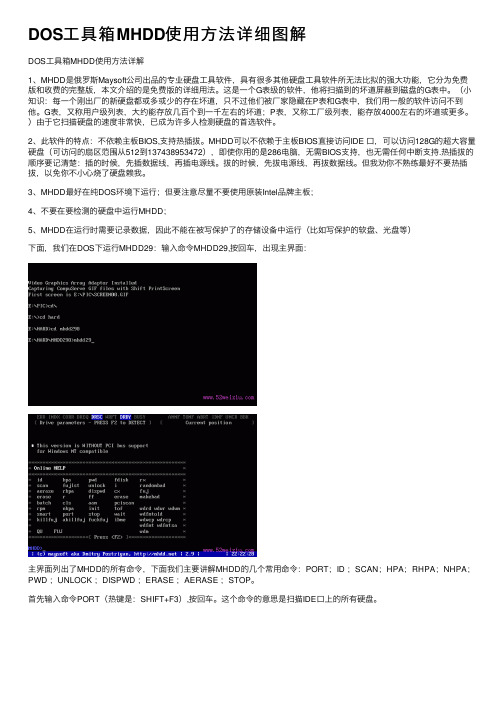
DOS⼯具箱MHDD使⽤⽅法详细图解DOS⼯具箱MHDD使⽤⽅法详解1、MHDD是俄罗斯Maysoft公司出品的专业硬盘⼯具软件,具有很多其他硬盘⼯具软件所⽆法⽐拟的强⼤功能,它分为免费版和收费的完整版,本⽂介绍的是免费版的详细⽤法。
这是⼀个G表级的软件,他将扫描到的坏道屏蔽到磁盘的G表中。
(⼩知识:每⼀个刚出⼚的新硬盘都或多或少的存在坏道,只不过他们被⼚家隐藏在P表和G表中,我们⽤⼀般的软件访问不到他。
G表,⼜称⽤户级列表,⼤约能存放⼏百个到⼀千左右的坏道;P表,⼜称⼯⼚级列表,能存放4000左右的坏道或更多。
)由于它扫描硬盘的速度⾮常快,已成为许多⼈检测硬盘的⾸选软件。
2、此软件的特点:不依赖主板BIOS,⽀持热插拔。
MHDD可以不依赖于主板BIOS直接访问IDE ⼝,可以访问128G的超⼤容量硬盘(可访问的扇区范围从512到137438953472),即使你⽤的是286电脑,⽆需BIOS⽀持,也⽆需任何中断⽀持.热插拔的顺序要记清楚:插的时候,先插数据线,再插电源线。
拔的时候,先拔电源线,再拔数据线。
但我劝你不熟练最好不要热插拔,以免你不⼩⼼烧了硬盘赖我。
3、MHDD最好在纯DOS环境下运⾏;但要注意尽量不要使⽤原装Intel品牌主板;4、不要在要检测的硬盘中运⾏MHDD;5、MHDD在运⾏时需要记录数据,因此不能在被写保护了的存储设备中运⾏(⽐如写保护的软盘、光盘等)下⾯,我们在DOS下运⾏MHDD29:输⼊命令MHDD29,按回车,出现主界⾯:主界⾯列出了MHDD的所有命令,下⾯我们主要讲解MHDD的⼏个常⽤命令:PORT;ID ;SCAN;HPA;RHPA;NHPA;PWD ;UNLOCK ;DISPWD ;ERASE ;AERASE ;STOP。
⾸先输⼊命令PORT(热键是:SHIFT+F3),按回车。
这个命令的意思是扫描IDE⼝上的所有硬盘。
好了,现在看到有两个硬盘,⼀个是西数40G,⼀个是迈拓2G。
ADATASSDToolbox_UserGuide_V10_TC

使用手冊ADATA® SSD(版本 1.0)大綱產品導覽 (3)簡介 (3)注意事項 (3)系統需求 (3)軟體限制 (4)執行 SSD Toolbox (5)硬碟資訊 (6)1.Disk Drive (6)2.Drive Details (7)3.硬碟空間訊息 (7)4.健康程度 (8)5.剩餘壽命 (8)6.S.M.A.R.T (8)診斷掃描 (11)工具程式 (12)1.安全抹除 (12)2.韌體更新 (14)3.Toolbox 升級 (14)4.資訊匯出 (14)系統最佳化 (15)1.固態硬碟最佳化 (15)2.作業系統最佳化 (15)系統資訊 (17)Q&A (18)參考文件 (18)23產品導覽簡介ADATA SSD Toolbox 是為了方便使用者能用簡單操作得到所需資訊的工具。
此外,它更能增加您使用固態硬碟的壽命以及加快固態硬碟的使用效能。
Toolbox 提供服務包括 硬碟資訊、診斷掃描、工具程式、系統優化和系統資訊。
注意事項▪ ADATA Toolbox 僅提供ADATA 系列固態硬碟產品。
▪ 在執行韌體更新或安全抹除等相關動作之前請備份您的重要資料! ▪ 建議您在每次做固態硬碟的插拔後按下重新整理( ),以維持您的Toolbox 中的硬碟狀態都是最新。
▪ 請注意您的使用環境是否支援熱插拔,如您並未在BIOS 啟動SATA 熱插拔功能,請在電源關閉時插拔裝置。
▪ 在Toolbox 使用非ADATA 固態硬碟系列產品,部分功能將不支援。
系統需求▪ 支援作業系統Microsoft Window® 7 32bit/ 64bit, Microsoft Windows® 8 32bit/ 64bit, Microsoft Windows ® 8.1 32bit / 64bit. ▪ 最少留10MB 空間執行Tool▪ 此軟體支援所有ADATA 現行的SSD 產品,軟體部分功能因不同的產品有使用上的限制,若需要更詳盡的資訊,請造訪相關連結:/index.php?action=ss_main&page=ss_software_6&lan=tw軟體限制5執行 SSD Toolbox您可以從以下網址下載 ADATA SSD Toolbox ,/index.php?action=ss_main&page=ss_software_6&lan=tw ,下載完請解壓縮檔案並雙擊 ”SSDTool.exe” , 開啟SSD Toolbox 的使用。
针对卡慢盘、显示告警并隔离被注入故障的ssd和hdd磁盘的方法

针对卡慢盘、显示告警并隔离被注入故障的ssd和hdd磁盘的方法全文共四篇示例,供读者参考第一篇示例:针对卡慢盘、显示告警并隔离被注入故障的SSD和HDD磁盘的方法随着科技的不断发展,存储设备在各行各业中扮演着至关重要的角色。
SSD(固态硬盘)和HDD(硬盘驱动器)是两种主要的存储设备,它们在各自领域内都有着独特的优势。
正如任何其他设备一样,这些存储设备也可能会受到各种故障影响,导致卡慢盘或显示告警。
本文将讨论针对这些问题的方法,以及如何隔离被注入故障的SSD和HDD磁盘。
让我们来看看可能导致存储设备故障的原因。
一些常见的因素包括磁盘损坏、物理损坏、数据传输错误等。
当存储设备出现问题时,可能会导致卡慢盘和显示告警。
在这种情况下,我们需要采取适当的措施来解决问题。
针对卡慢盘问题,可以采取以下方法来解决:1. 清理存储空间:及时清理不必要的文件和数据,释放存储空间。
2. 升级固件:对SSD和HDD的固件进行升级,以修复可能存在的bug和问题。
3. 检查硬件连接:确保存储设备与计算机正确连接,避免连接不良导致的问题。
4. 检查系统设置:检查操作系统设置,确保存储设备能够正常工作。
1. 查看告警信息:及时查看存储设备的告警信息,了解问题所在。
2. 备份重要数据:在处理问题之前,务必备份重要数据,以免数据丢失。
3. 重启设备:尝试重启存储设备,有时可以解决一些问题。
4. 检查磁盘健康:使用专业的检测工具检查SSD和HDD的健康状况,及时发现问题并解决。
1. 使用安全软件:安装安全软件来防止外部恶意注入,保护存储设备安全。
2. 隔离感染设备:一旦发现磁盘被注入故障,立即隔离设备,不再使用。
3. 数据恢复:尝试使用专业的数据恢复工具来尝试恢复故障磁盘上的数据。
4. 更换磁盘:如果数据无法恢复或存储设备无法修复,那么需要更换新的磁盘。
针对卡慢盘、显示告警并隔离被注入故障的SSD和HDD磁盘,我们需要及时识别问题,并采取适当的方法来解决。
SCv3000和SCv3020存储系统入门指南.pdf_1700415797.7770145说明书
SCv3000 and SCv3020 Storage SystemGetting Started GuideNotes, Cautions, and WarningsNOTE: A NOTE indicates important information that helps you make better use ofyour product.CAUTION: A CAUTION indicates either potential damage to hardware or loss of data and tells you how to avoid the problem.WARNING: A WARNING indicates a potential for property damage, personal injury,or death.© 2017 – 2018 Dell Inc. or its subsidiaries. All rights reserved. Dell, EMC, and other trademarks are trademarks of Dell Inc. or its subsidiaries. Other trademarks may be trademarks of their respective owners.2018 - 11Rev. A01Setting Up the Storage System Consider the following best practices when setting up an SCv3000 and SCv3020 storage system.•Dell recommends that you use a dedicated SAN network for data transmission when using a Fibre Channel or iSCSI storage system.•Always configure redundant data paths to provide alternate paths to and from the host server should one of the data paths become disabled.•Before connecting any cables between the storage system and host server or expansion enclosure, physically label each port and connector.•Always follow proper power-up and power-down procedures when cycling power across the network. Verify that critical network components are on separate power circuits.NOTE: This product is intended for restricted access locations, such as a dedicatedequipment room or equipment closet.WARNING: If installed in a closed or multi-unit rack assembly, the operatingambient temperature of the rack environment may be greater than room ambient temperature. Therefore, consideration should be given to installing the equipment in an environment compatible with the maximum ambient temperature (Tma) specified by the manufacturer.Safety WarningsT wo person lift requiredA fully configured SCv3000 and SCv3020 storage systemweighs approximately 43 kg (95 lb). Use appropriate liftingmethods when installing the storage system.Laser Radiation for Fibre Channel Storage SystemsSetting Up the Storage System3The unit is certified in the U.S. to conform to the requirements of DHHS 21 CFR, chapter 1 Subchapter J for Class I (1) laser products, and elsewhere is certified as a Class I laser product conforming to the requirements of IEC 60825-1:2007.Class I laser products are not considered to be hazardous. The laser system and unit are designed so there is never any human access to laser radiation above a Class I level during normal operation, user maintenance or prescribed service condition.Topics:•Locating Your Service T ag•Other Information You May Need•Installation and Configuration•NOM Information (Mexico Only)•T echnical SpecificationsLocating Your Service TagYour storage system is identified by a unique service tag and Express Service Code.The service tag and Express Service Code are found on the front of the system by pulling out the information tag. Alternatively, the information might be on a sticker on the back of the storage system chassis. This information is used by Dell to route support calls to the appropriate personnel.NOTE: The Quick Resource Locator (QRL) code on the information tag is unique toyour system. Scan the QRL to get immediate access to your system information using your smart phone or tablet.Other Information You May NeedTo install the storage system, you may need the following additional information:•SCv3000 and SCv3020 Storage System Owner’s Manual4Setting Up the Storage SystemProvides information about an SCv3000 and SCv3020 storage system, such ashardware features, replacing hardware components, and technical specifications.•Storage Manager Administrator’s GuideProvides instructions for using the Storage Manager software.•Unisphere and Unisphere Central for SC Series Administrator’s Guide Provides instructions and information for managing storage systems using Unisphere and Unisphere Central for SC Series.Installation and ConfigurationBefore you begin installation, make sure that the site where you plan to install the storage system has standard power from an independent source or a rack power distribution unit with a UPS.In addition, verify that there is a 3U space in the lower 20U of the rack to install the storage system. If you plan to install the storage system above the lower 20U of a rack, a customer-provided mechanical lift must be used to avoid injury.Unpacking Storage Center EquipmentUnpack the storage system and identify the items in your shipment.Setting Up the Storage System5Figure 1. SCv3000 and SCv3020 Storage System Components1Documentation2Storage system3Rack rails4USB cables (2)5Power cables (2)6Front bezelInstall the Storage System in a RackInstall the storage system and other Storage Center system components in a rack.About this taskMount the storage system and expansion enclosures in a manner that allows for expansion in the rack and prevents the rack from becoming top‐heavy.The SCv3000 and SCv3020 storage system ships with a ReadyRails II kit. The rails come in two different styles: tool-less and tooled. Follow the detailed installation instructions located in the rail kit box for your particular style of rails.NOTE: Dell recommends using two people to install the rails, one at the front of the6Setting Up the Storage SystemSteps1 Position the left and right rail end pieces labeled FRONT facing inward.2 Align each end piece with the top and bottom holes of the appropriate U space.Figure 2. Attach the Rails to the Rack3 Engage the back end of the rail until it fully seats and the latch locks into place.4 Engage the front end of the rail until it fully seats and the latch locks into place.5 Align the system with the rails and slide the storage system into the rack.Setting Up the Storage System7Figure 3. Slide the Storage System Onto the Rails6 Lift the latches on each side of the front panel and tighten the screws to the rack.8Setting Up the Storage SystemFigure 4. Tighten the ScrewsIf the Storage Center system includes expansion enclosures, mount the expansion enclosures in the rack. See the instructions included with the expansion enclosure for detailed steps.Install the Front BezelInstall the bezel on the front of the storage system.Steps1 Hook the right end of the bezel onto the storage system.Setting Up the Storage System9Figure 5. Front Bezel2 Insert the left end of the bezel into the securing slot until the release latch snaps intoplace.3 Secure the bezel with the keylock.Next stepInstall the expansion enclosures in the rack. See the instructions included with the expansion enclosure or in the expansion enclosure Service Guide for detailed steps.Connect the Power CablesConnect power cables to the storage system.1 Make sure that the power switches are in the OFF position before connecting thepower cables.2 Connect the power cables securely to both power supply/cooling fan modules in thestorage system chassis.10Setting Up the Storage System3 Use the straps to secure the power cables to the storage system chassis.Figure 7. Secure the Power Cables4 Plug the other end of the power cables into a grounded electrical outlet or a separatepower source such as an uninterrupted power supply (UPS) or a power distributionunit (PDU).NOM Information (Mexico Only)The following information is provided on the device described in this document in compliance with the requirements of the official Mexican standards (NOM):T echnical SpecificationsThe technical specifications of the SCv3000 and SCv3020 storage systems are displayed in the following tables.。
金士顿 SSD 管理器用户指南说明书

Kingston®SSD ManagerUser Guide(V.1.0.1.3)FIRMWARE AND FIRMWARE UPDATES ARE PROVIDED AT KINGSTON'S DISCRETION IN CONNECTION WITH CERTAIN KINGSTON PRODUCTS.THE FIRMWARE AND FIRMWARE UPDATES ARE PROVIDED"AS IS"AND ARE USED AT YOUR SOLE RISK WITH NO WARRANTIES,CLAIMS,OR REPRESENTATIONS FROM KINGSTON WHATSOEVER.KINGSTON EXPRESSLY DISCLAIMS ALL SUCH WARRANTIES OF ANY KIND,WHETHER EXPRESS,IMPLIED OR STATUTORY,WITH RESPECT TO THE FIRMWARE AND FIRMWARE UPDATES INCLUDING,WITHOUT LIMITATION,WARRANTIES OR CONDITIONS OF QUALITY,PERFORMANCE,NON-INFRINGEMENT, MERCHANTABILITY,OR FITNESS FOR USE FOR A PARTICULAR PURPOSE.KINGSTON DOES NOT REPRESENT OR WARRANT THAT THE FIRMWARE OR FIRMWARE UPDATES WILL ALWAYS BE AVAILABLE,ACCESSIBLE, UNINTERRUPTED,TIMELY,SECURE,ACCURATE,COMPLETE OR ERROR-FREE,INCLUDING BUT NOT LIMITED TO THE ACCURACY OR COMPLETENESS OF ANY INFORMATION,TEXT,GRAPHICS,LINKS OR OTHER ITEMS CONTAINED WITHIN THE FIRMWARE.NO LICENSE,EXPRESS OR IMPLIED,BY ESTOPPEL OR OTHERWISE,TO ANY INTELLECTUAL PROPERTY RIGHTS IS GRANTED BY ALLOWING THE DOWNLOAD OF ANY FIRMWARE AND/OR FIRMWARE UPDATE,EXCEPT AS PROVIDED HEREIN.IntroductionKingston®SSD Manager is an application that provides users with the ability to monitor and manage various aspects of their Kingston®Solid State Drive.With Kingston®SSD Manager you will be able to:∙Monitor drive health,status,and disk usage∙View drive identification data including model name,serial number,firmware version,and other relevant information∙Utilize Self-Monitoring,Analysis,and Reporting Technology(SMART)and export detailed reports in text format ∙Update drive firmware∙Securely erase data∙Manage TCG Opal and IEEE1667∙Overprovision with Host Protected Area(HPA)(DC400series only)Supported Operating SystemsKingston®SSD Manager is supported on the following operating systems:∙Windows®10∙Windows®8.1∙Windows®8∙Windows®7SP1System RequirementsIn order to use Kingston®SSD Manager you must have:∙One or more Kingston®SSDs∙AHCI mode set in BIOS∙Administrator privileges in Windows®Main WindowThe main window allows you to quickly view device information and health status.To rescan for devices click the refresh button.If you have more than one Kingston®SSD you can switch between them in the left panel.Switching between tabs is done in the right panel.The bottom panel provides the following drive information:∙Partition and disk usage∙SMART health overview∙SSD life remaining and spare blocks∙Temperature and power on hoursFirmware TabThe Firmware tab provides the following drive information:∙Physical device path∙Volume information∙Vendor/Model∙Serial number∙Firmware versionIf there is a firmware update available for your Kingston®SSD you will be able to click on the firmware update button to begin the update.Once the firmware update process has completed it is recommended to safely shut down your system and leave it powered off for10seconds before powering back on again.Operations TabThe Operations tab includes any special operations that may be applicable to your Kingston®SSD.This tab will be hidden from view if your model of SSD does not support any special operations.OverprovisioningThe overprovisioning feature allows you to manage the overprovisioning of your Kingston®SSD by setting a Host Protected Area(HPA).Overprovisioning is the practice of reducing the usable capacity of an SSD in order to increase both its performance and endurance.This feature is only supported on the DC400series of Kingston®SSDs.If you would like to use this feature you must first remove all partitions from the SSD.You may also need to clean the SSD using diskpart.For best performance a secure erase is recommended.Now enter the desired capacity in gigabytes(GB)and click the commit button to apply your changes.After the process completes successfully you must disconnect and then reconnect the SSD in order for the operating system to properly detect the new capacity.Note:If the overprovisioning process fails please power cycle the SSD and try again.SMART TabThe SMART tab allows you to monitor various attributes related to the health and status of your Kingston®SSD.Click the refresh data button to refresh the SMART information currently being displayed.Click the export data button to save the SMART information to a text file.You may scroll up and down on this tab to view all of the various SMART attributes.The attributes with colored gauges next to them allow you to quickly monitor their status.There is also a table listing all of the supported SMART attributes along with their technical details and values:∙Attribute:The attribute number and description.∙Normalized:The current normalized value of the attribute.∙Worst:The lowest recorded normalized value of the attribute.∙Threshold:The value that the attribute should not exceed under normal operation.∙Raw:Raw value of the attribute.∙Flags:The number of flags associated with the attribute.Security TabThe Security tab allows you to manage and view the current status of the following security features of your Kingston®SSD:∙ATA Security:View the current ATA security status.You may be able to perform an ATA secure erase on a secondary non-partitioned drive by clicking on the secure erase button.ATA secure erase will erase all data on the drive.This will restore your Kingston®SSD to its fresh out of box condition.ATA secure erase may not be available on allsystems.∙TCG Opal:View the current TCG status.This only applies to Kingston®SSDs that support TCG Opal.If your drive is TCG enabled and you would like to restore it to a disabled state then you have the ability to perform a TCG revert using the PSID.The PSID is a string of32letters and numbers located on the drive label.The SSD must be connected as a secondary drive and you must correctly type in the PSID on the label.Once you have PSID typed in click the TCGrevert button to revert the drive.TCG revert will cryptographically erase all data on the drive.∙IEEE1667:View the current IEEE1667status.This only applies to Kingston®SSDs that support TCG Opal.You can enable or disable IEEE1667support by clicking on the IEEE1667enable/disable button.It is recommended to only have IEEE1667enabled if you plan to use hardware encryption in BitLocker according to the Microsoft®eDrivestandard.Events TabThe Events tab contains an event log that records all actions since the application was launched.For additional support related the Kingston®SSD Manager,please contact our Technical Support team@/support。
SUN 系统管理指南 设备和文件系统 说明书
系统管理指南:设备和文件系统Sun Microsystems,Inc.4150Network CircleSanta Clara,CA95054U.S.A.文件号码819–7062–102006年9月版权所有2006Sun Microsystems,Inc.4150Network Circle,Santa Clara,CA95054U.S.A.保留所有权利。
对于本文档中介绍的产品,Sun Microsystems,Inc.对其所涉及的技术拥有相关的知识产权。
需特别指出的是(但不局限于此),这些知识产权可能包含一项或多项美国专利,或在美国和其他国家/地区申请的待批专利。
美国政府权利-商业软件。
政府用户应遵循Sun Microsystems,Inc.的标准许可协议,以及FAR(Federal Acquisition Regulations,即“联邦政府采购法规”)的适用条款及其补充条款。
本发行版可能包含由第三方开发的内容。
本产品的某些部分可能是从Berkeley BSD系统衍生出来的,并获得了加利福尼亚大学的许可。
UNIX是X/Open Company,Ltd.在美国和其他国家/地区独家许可的注册商标。
Sun、Sun Microsystems、Sun徽标、Solaris徽标、Java咖啡杯徽标、、Java和Solaris是Sun Microsystems,Inc.在美国和其他国家/地区的商标或注册商标。
所有SPARC商标的使用均已获得许可,它们是SPARC International,Inc.在美国和其他国家/地区的商标或注册商标。
标有SPARC商标的产品均基于由Sun Microsystems,Inc.开发的体系结构。
FireWire和FireWire徽标是Apple Computer,Inc.的商标,其使用已获得许可。
X/Open是X/Open Company,Ltd.的注册商标。
DLT已申请为Quantum Corporation在美国和其他国家/地区的商标。
硬盘故障处理大全
硬盘故障处理大全1、分区表错误的处理故障现象:开机后,屏幕上显示:“Invalid partition table” 硬盘不能启动,可从软盘启动。
故障分析与处理:造成该故障的原因一般是硬盘主引导记录中的分区表有错误,当指定了多个自举分区(只能有一个自举分区)或病毒占用了分区表时将有上述提示。
主引导记录(MBR)位于0磁头0柱面1扇区,由FDISK.EXE对硬盘分区时生成。
MBR包括主引导程序、分区表和结束标志55AAH 3部分,共占一个扇区。
主引导程序中含有检查硬盘分区表的程序代码和出错信息、出错处理等内容。
当硬盘启动时,主引导程序将检查分区表中的自举标志。
若某个分区为自举分区,则有分区标志80H,否则为00H,系统规定只能有一个分区为自举分区,若分区表中含有多个自举标志时,主引导程序会给出“Invalid partion table”的错误提示。
最简单的解决方法是用NDD 修复,它将检查分区表中的错误,若发现错误,将会询问您是否愿意修改,您只要不断地回答“Yes”即可修正错误,或者用备份过的分区表覆盖它也行。
如果是病毒感染了分区表,格式化是解决不了问题的,可先用杀毒软件杀毒,再用NDD进行修复。
如果上述方法都不能解决,就先用FDISK重新分区,但分区大小必须和原来的分区一样,这一点尤为重要,分区后不要进行高级格式化,然后用NDD进行修复。
修复后的硬盘不仅能启动,而且硬盘上的信息也不会丢失。
其实用FDISK 分区,相当于用正确的分区表覆盖原来的分区表。
尤其当用软盘启动后不认硬盘时,可用此方法。
2、硬盘不能工作的故障原因和处理故障现象:微机无法用硬盘启动,检查CMOS参数没有问题。
用软盘启动后可转入C:u25552提示符,但是不能对硬盘进行任何操作。
故障分析与处理:用软盘启动后可转入C:u25552提示符,说明系统是可以识别硬盘驱动器的。
硬盘不仅不能引导系统,而且也不能进行其他操作,说明故障原因可能是硬盘的主引导区或分区表遭到破坏,弄得硬盘不能正常工作。
开机 chkdsk is verifying files(stage 1 of 3)解决方法
开机chkdsk is verifying files(stage 1 of 3)解决方法1、正常关机的情况下,每次重启后都要自检硬盘,后来经过多方查找终于找到解决方法:单击“开始→运行”,在“运行”对话框中输入“regedit”打开注册表编辑器,依次选择“HKEY_LOCAL_MacHINE\SYSTEM\CurrentControlSet\Control\S ession Manager”子键,然后在右侧窗口中找到“BootExecute”键值项并将其数值清空,按“F5”键刷新注册表即可。
2、控制面板〉性能和维护〉管理工具〉事件查看器,看看有没关机是未正常退出的服务和程序,有些程序在关闭时会把内存中的数据写入硬盘,如果失败就会引起磁盘检测。
3、最坏的可能,坏道。
逻辑坏道可以PC3000或效率源加以修复,物理坏道虽也可以隔离和屏蔽,但是会极大的影响硬盘的正常寿命。
一般来说第一个办法就可以解决这个烦恼了很久的问题了。
网络其它说法:CHKDSK is verifying files (stage1 of 3)...file verfying completedCHKDSK is verifying indexes (stage2 of 3)...0 percent completed[pre]是磁盘错误.以D盘为例运行命令行cmd输入chkntfs d:它会显示此盘是否有问题,如果有问题会提示你扫描错误. 如有问题输入chkdsk /f d:可能要重启,并且还会出现那个画面.之后再进cmd输入chkntfs /x d:如果有多个盘可以同时解决如:chkntfs /x c: d: e: 等等chkntfs /x D:试了吗?要你找磁盘问题是次要的,这个命令才是最主要的.[/pre][pre]解决这个问题最简单的办法:点击开始,运行,输入regedit 找到: HKEY_LOCAL_MACHINE\SYSTEM\CurrentControlSet\Control\S ession Manager,打开右边的BootExecute,将其中的值删除就行了说你说复制10G的要70分钟,这是有点问题,你听到硬盘有响声不,运行的时候,沙沙的响声,如果没的话就不是硬盘物理损坏,应该是你硬盘的磁头出错误了,解决的办法:一、你用张GHOST系统盘,重启后进到里头的PQ8.5,然后等它检测,等它修复二、用张带winpe的光盘,进到winpe,在程序里头选择PTDD3.0,然后用它修复下你的注册表和磁头,这个工具在网上也有的下载,不过我推荐你在winpe里头用它……这样的话,问题应该就能解决了~[/pre][pre][pre][pre]你可以吧硬盘的系统文件改成NTFS 的格式的基本上能结局在运行里输入CMD 然后convert c:/fs:ntfsC盘完了你就打convert D:/fs:ntfs convert E:/fs:ntfs convert F:/fs:ntfs[/pre][pre][pre]系统自动修复功能这个是你的硬盘数据出现错误,有两种方法解决。
os390操作手册
第一步:配置与大型机的终端通信第二步:在程序界面中点击链路参数并按管理员的说明输入主机IP地址及端口号(以192.168.2.2 端口3270为例)点击确认并保存此链接信息。
之后可在“WIN开始”菜单中选择保存的链接(以刚保存的链接为“2.WS”为例)。
成功连接主机后程序界面如下输入“TSO”并回车(回车为右CTRL键或小键盘的回车)或输入“TSO 管理员为你分配的用户名”并回车分别出现以下界面:界面如下输入分配帐户的密码并按回车登录(初次登录系统会要求更改密码,不得与原密码重复)两次输入新密码并确认后回车,登录成功则显示如下界面按下回车后进入OS390主界面按下回车后信息提示框消失此时即可进行各种操作。
一、新建文件输入“3”并回车进入以下界面按2新建一个数据集,进入如下界面在Data Set Name处输入新文件名称,为方便查找输入’USER03.DATA’也可直接输入DATA,系统会自动为文件加上USER03的前缀,’’起限定文件名的作用在Option处输入A并回车,表示为分配新的数据集。
回车后进入如下详细设定界面。
其中V olume serial为当前用户可写卷标,一般为系统管理员分配,此处示例使用“WORK01”卷标。
Space units为文件计算大小单位,在常用磁带3390-3中,一个TRKS(磁道)可保存40到50KB的数据,而一个CYLS(簇)为15磁道,一般使用TRKS计算文件大小。
Primary quantity为文件初次分配存储空间大小,Secondary quantity为文件内容溢出再分配存储空间大小,根据实际情况自由设定,但一般系统会有文件增长次数,本系统中为16次,亦有128次的系统。
Record format为记录格式,FB为Fixed Block的缩写,意即当文件不够Record length大小时,根据Record length补足。
Block Size则为块大小。
- 1、下载文档前请自行甄别文档内容的完整性,平台不提供额外的编辑、内容补充、找答案等附加服务。
- 2、"仅部分预览"的文档,不可在线预览部分如存在完整性等问题,可反馈申请退款(可完整预览的文档不适用该条件!)。
- 3、如文档侵犯您的权益,请联系客服反馈,我们会尽快为您处理(人工客服工作时间:9:00-18:30)。
C. No display, even 0x11 and 0x29 are sent D. E. F. End of the display has tearing effect Display has red / blue / green dots Display Shift
SSD2828 Dec 2012 P. 6
Check List 5. TS5000 debug guide A. AP SYNC and RGB check
SSD2828
Dec 2012
P. 7
1A Power Supply Voltage MAVDD / MDVDD / VCC12A Connected to 1.2V Maximum current consumption is about 40mA VDD3IO / VDD3IOC / ATC[1:0] Connected to 1.8 ~ 3.3V Maximum current consumption is below 1mA
Dec 2012 P. 20
SSD2828
2C DOTCLK/HSYNC/VSYNC/DEN setting Related commands: 0xB1 0xB2 0xB3 0xB4 0xB5 0xB6 SYNC width setting Back porch setting Front porch setting Horizontal active period Vertical active period Video mode and pixel format
PCLK Color # of Lane 55.0 24 4 MHz Bits
Min.
Per Lane Speed
330
Mbps
SSD2828
Dec 2012
P. 18
2A HS clock setting (PLL clock) Related commands: 0xB9 0xBA Control PLL on/off PLL freq. setting
E.g. TX_CLK = 10MHz, 0xBA 0x8023, 0xBB 0x000A LP clock = 350Mbps / 10 / 8 = 4.4MHz
PLL freq. 0xBB 0x000A 1 byte PLL generating 1 bit LP clock Convert unit “bps” to “Hz”
PLL freq. can only be changed when PLL is off E.g. TX_CLK = 10MHz, 0xBA 0x8023 PLL = 350Mbps
SSD2828
Dec 2012
P. 19
2B LP clock setting Related commands: 0xB9 0xBA 0xBB Control PLL on/off PLL freq. setting LP clock setting
SSD2828
Dec 2012
P. 12
1C SPI Type PS[4:0] = 000010, 4 wire 8 bit SPI interface CSX0 is connected to CS pin of AP Make sure sending the LSB 8bit data first
SSD2828
Dec 2012
P. 13
1D DOTCLK/HSYNC/VSYNC/DEN/RGB setting
Sync Pulses event SYNC width will not be counted for back porch value
SSD2828
Dec 2012
P. 14
1D DOTCLK/HSYNC/VSYNC/DEN/RGB setting
SSD2828
Dec 2012
P. 17
2A HS clock setting (PLL clock) Minimum PLL clock frequency is related to PCLK E.g. PCLK = 55MHz, 24bit color, 4 Lanes Min. PLL freq. = 330Mbps
RGB or BGR setting
Following is an example:
C O D23 D22 D21 D20 D19 D18 D17 D16 D15 D14 D13 D12 D11 D10 D9 D8 D7 D6 D5 D4 D3 D2 D1 D0 0 1 B7 R7 B6 R6 B5 R5 B4 R4 B3 R3 B2 R2 B1 R1 B0 R0 G7 G7 G6 G6 G5 G5 G4 G4 G3 G3 G2 G2 G1 G0 R7 R6 R5 R4 R3 R2 R1 R0 G1 G0 B7 B6 B5 B4 B3 B2 B1 B0
SSD2828
Dec 2012
P. 10
1C SPI Type PS[4:0] = 00000, 3 wire 24 bit SPI interface CSX0 is connected to CS pin of AP Make sure the MSB 8 bits are correct
0x70
D. DOTCLK/HSYNC/VSYNC/DEN/RGB setting E. Jumper setting
SSD2828
Dec 2012
P. 3
Check List 2. Software A. B. HS clock setting (PLL clock) LP clock setting
C. DOTCLK/HSYNC/VSYNC/DEN setting D. E. F. Number of MIPI Lane setting VC setting for video and SPI mode RGB Data setting
SSD2828 Dec 2012 P. 8
1B External Clock Source Setting of TEST[2:0] = 000 TX_CLK = 8 ~ 30MHz
(Same voltage as VDD3IO)
SSD2828
Dec 2012
P. 9
1B External Clock Source Setting of TEST[2:0] = 001 Crystal freq. = 8 ~ 30MHz
HSYNC is active low DEN is active high
VSYNC is active low
SSD2828
Dec 2012
P. 16
1E Jumper setting CM = 0, 16M/262k/64k color display mode SHUT = 1, using software command to control display on/off IF_SEL = IF_SEL2 = 0, normal operation
0xB6
24 / 18 / 16 bpp setting
Following is an example:
SSD2828
Dec 2012
P. 24
3A HS mode MIPI connection If there is no MIPI connection with Rx HS mode has about 1V peak to peak waveform
0x72
SSD2828 Dec 2012 P. 11
1C SPI Type PS[4:0] = 000001, 3 wire 8 bit SPI interface CSX0 is connected to CS pin of AP Make sure the MSB bit (D8) is “0” for command and “1” for data Make sure sending the LSB 8bit data first
SSD2828 Getting Start User Guide
Version 03
SSD2828
Dec 2012
P. 1
Block Diagram
1.8 ~ 3.3V
1.2V
Power DOTCLK VSYNC /
AP
HSYNC / DEN RGB Data SPI Interface
Tx: SSD2828
SSD2828 Dec 2012 P. 4
Check List 3. MIPI output A. B. HS mode MIPI connection Video mode output
SSD2828
Dec 2012
P. 5
Check List 4. Q & A A. No display, MIPI video cannot sync with VSYNC B. No display, PLL > 1Gbps per lane
Normally, all the VC should be “00”, so 0xB8 0x0000 for most of the case
SSD2828
Dec 2012
P. 23
2F RGB Data setting Related command: 0xD6
0xD6 0x0004 0x0005
Legend
DATAN0
DATAP0
CLKP
HS mode
SSD2828
Dec 2012
P. 26
3B Video mode output Blinking period (LP mode period) must be sync. with VSYNC