空预器吹灰器IK-AH-500 IM-3146说明书
艾尔斯·科普科特冷凝式空气干燥器产品说明书
Why dry yourcompressed air?Compressed air contains oil, solid particles and water vapors. It is theinherent result of the compression process, which concentrates thenatural water vapors and particles in the air that surrounds us. Thisuntreated compressed air poses a substantial risk to your air system andend products. Its moisture content alone can cause corrosion in pipework, premature failure of pneumatic equipment, product spoilageand more. An air dryer is therefore essential to protect your systemsand processes.Refrigerant dryersby Atlas CopcoAtlas Copco’s refrigerant dryers provide the clean, dry air you need+) to expand the life of your equipment and ensure the quality of yourproducts. Our FD and FX dryers are designed in-house and tested usingthe most stringent methods. They meet or exceed the internationalstandards for compressed air purity and are tested according toISO 7183:2007.253614Controls the speed of the compressor to match your air demand and ensure the highest possible energy savings.1Opens the drain only when needed to eliminate unnecessary loss of compressed air during timed draining.4Counter-flow compact brazed plate or aluminum heat exchanger, with air-to-air side for optimum cooling efficiency and the lowest possible pressure drop.2®Touch controllerProvides advanced control and allows for remote monitoring.5Low velocity with high separation efficiency, even in low flow conditions.3Ensures plug-and-play installation.6VSD for superior energy savingsAtlas Copco’s in-house developed VSD technology matches your FD dryer’s power consumption to your production’s actual airflow. While a traditional refrigerant dryer can only be turned on or off, Atlas Copco’s FD VSD mirrors your production’s demand for compressed air as it fluctuates during the day, week or year. This ensures supreme energy savings as well as a stable dew point.Minimal environmental impactFD VSD dryers use the CFC-free R410A refrigerant, which has an ozone depletion potential (ODP) of zero. The refrigerant meets the strict F-Gas regulations and, due to its low powerconsumption, has an an outstanding TEWI (Total Equivalent Warming Impact) performance.Optimum performance and safety in all conditions• Hot gas bypass valve prevents freezing at lower loads.• The extremely reliable R410A rotary compressor provides the best performance with minimum environmental impact.Capillary tubes cope with all conditions – no moving parts for extra reliability.• Condenser with louvered fin technology for improved performance in dusty environments.Advanced remote monitoring and control• High-tech Elektronikon ® Touch controller with warning indications, dryer shutdown and maintenance scheduling. • Standard SMARTLINK remote monitoring to maximize air system performance and energy savings.Robust and compact design• Forklift opening for smooth transport. • Easy front and side panel access.• No bulky thermal mass heat exchanger needed to save on energy.FiltersIf your production requires higher levels of air quality andfiltration, UD + filters can be added on to your FD VSD dryer.Power consumptionVSD dryerFixed speed dryerSupreme energy efficiency• The FD offers a low pressure drop – typically below 0.2 bar/2.9 psi – and minimal energy consumption.• The compact brazed plate or aluminum heat exchanger was designed specifically to provide optimal pre-cooling and the lowest possible pressure drop.• The electronic no-loss condensate drain comes with a level sensor to open the drain only when needed, preventing unnecessary loss of compressed air.Comprehensive control and monitoring options• The Elektronikon ® Alpha controller displays the pressure dew point and relative humidity.• Remote alarm and start/stop control through voltage-free contact.• Additional features such as alarm history and standard remote visualization.Easy installation and long maintenance intervals• Small footprint thanks to an innovative all-in-one design. • Delivered ready for use, minimizing costly production downtime.Low environmental impactFD dryers use CFC-free refrigerants (R134A and R410A) with an ozone depletion potential (ODP) of zero.Counter-flow compact brazed plate or aluminum heatexchanger, with air-to-air side for optimum cooling efficiency and the lowest possible pressure drop.2condensate drainWith level sensor, backup manual drain and drain alarm.4separatorLasts longer thanks to limited vibrations, minimal moving parts, and reduced risk of leakage.1Reduces energy consumption and optimizes the pressure dew point at very low temperatures.5Low velocity with high separation efficiency even in low flow conditions.3Ensures stable pressure dew point and prevents freezing at lower loads.6connectionAllows for plug-and-play installation.8Eliminates the chance of moisture entering the compressed air system.7Reliable performance in tough conditions• Hot gas bypass valve prevents freezing at lower loads.• R134A piston compressor with high coefficient of performance (extremely reliableR410A rotary compressor for models FD 60-FD 95) provides the best performance with minimum environmental impact. Capillary tubes cope with all conditions – no moving parts for extra reliability.• Condenser with louvered fin technology for improved performance in dusty environments.3748152637481526Pressure dew point precisionThe FX comes in a wide range of sizes (7-300 l/s or 15-636 cfm) to offer a steady pressure dew point as low as +3°C/+37.4°F. Its easy to use digital display precision-measures and monitors the pressure dew point and dryer performance.Digital display• Pressure dew point: exact measurement and visual monitoring. • Status: refrigerant compressor and fan.• Alarms: high/low pressure dew point and probe failure.• Service warning.ReliableBuilt according to the stringent Atlas Copco standards, the FX is made of high quality, generously sized components.Hot environmentsHigh ambient temperatures can put your equipment to the test. The FX range offers several high temperature models that ensure dependable performance in conditions up to 46°C/115°F.Significant cost savings• Increased reliability and lifetime of tools and equipment.• Reduced pipe work leaks and thus a lower energy bill.• Less equipment breakdowns and operational interruptions.• Minimal chance of product damage as a result of moisture carryover.Sustainable refrigerantThe FX range comes with refrigerant that is compliant with F-Gas regulations to ensure the lowest possible carbon footprint and energy consumption.separatorNo chance of moisture entering the compressed air system.1Ensures stable pressure dew point and eliminates the possibility of condensate freezing.2Provides peace of mind through precise monitoring of pressure dew point.3connectionAllows for plug-and-play installation.4componentsFor straightforward servicing.5Offers high efficiency for better pressure dew point.6with integrated liquid separatorLasts longer thanks to limited vibrations, minimal moving parts, and reduced risk of leakage.8For a small footprint.7VSD:a game-changer in energy savingsWhen purchasing a refrigerant dryer, the main focus is usually on the initial cost. However, this only represents approximately 10% of the lifecycle cost of the dryer. Energy, maintenance and installation make up the bulk of your actual dryer costs. Direct and indirect (pressure drop) energy costs are the most important.Indirect energy costsIndirect energy costs are related to the extra energy your aircompressor must consume to overcome the pressure drop that takesplace in the air dryer. By design, Atlas Copco FD VSD dryers offer a lowpressure drop and efficient heat transfer – both of which contribute toFD VSD 100-300:Elektronikon ® Touch controller• 4.3-inch high-definition color display with clear pictograms and service indicator.• Internet-based dryer visualization using a simple Ethernet connection.• Automatic restart after voltage failure.• Built-in SMARTLINK online monitoring.• More flexibility: four different week schedules.• Graphical service plan indication.• Remote control and connectivity functions.SMARTLINK & Total ResponsibilityGet the most out of SMARTLINK as part of a Total Responsibility Plan. Step back, relax, and let our service engineers monitor your compressed air system. We know exactly when to serviceyour machines, diagnose any issues and be there on time to fix them.FD 5-95:Elektronikon ® Alpha controller• Exact measurement and visual monitoring of pressure dew point and ambient temperature.• High/low pressure dew point alarm.• Relative humidity indicator.• Energy saving mode.• Switch off at freezing alarm.• Alarm history and standard remote visualization.FX 1-16: Digital display• Pressure dew point: exact measurement and visual monitoring. • Energy saving mode.• Alarms: high/low pressure dew point and probe failure.•Service warnings.SMARTLINK: Data Monitoring ProgramSMARTLINK captures live data from your compressed air equipment and translates it in clear insights. At a glance, you can check uptime, energy efficiency and machine health.• Remote monitoring that helps you optimize your compressed air system and save energy and costs.• Provides a complete insight in your compressed air network.• Anticipates potential problems by warning you upfront.• Efficient service planning and parts handling to give you improved uptime.Advanced controlAtlas Copco’s refrigerant dryers are built to reliably and efficiently deliver quality air. But in the end, it’s all about how they perform on your work floor, meeting your individual needs and responding to your specific conditions. That is why the FD VSD, FD and FX come with comprehensive control options to allow you to get the best performance from your Atlas Copco dryer.Remote monitoringHow refrigerant dryers workA refrigerant dryer uses a refrigerant circuit and heat exchanger(s) to pre-coolair, refrigerate it to condense out moisture vapor, and then re-heat the air toAir circuit1Air-to-air heat exchanger: Incoming air is cooled downby the outgoing dry, cold air2Air-to-refrigerant heat exchanger: The air is cooled tothe required dew point by the refrigerant circuit. Thewater vapor condenses into water droplets3Integrated water separator: The moisture is collectedand evacuated by the electronic drainRefrigerant circuit4Refrigerant compressor: Compresses the gaseousrefrigerant to a higher pressure5Regulation device: The hot gas bypass valve regulatesthe dryer to prevent freezing at lower load conditions6Refrigerant condenser: Cools the refrigerant so that itchanges from a gas to a liquid7Refrigerant filter: Protects the expansion device fromharmful particles8Thermostatic expansion valve: The expansion processreduces the pressure and cools the refrigerant further9Liquid separator: Ensures that only refrigerant gasenters the compressorHot refrigerant gasCold refrigerant liquidExpanded refrigerant liquid2935 0868 41 © 2020, A t l a s C o p c o A i r p o w e r N V , B e l g i u m . A l l r i g h t s r e s e r v e d . D e s i g n s a n d s p e c i fi c h a n g e w i t h o u t n o t i c e o r o b l i g a t i o n . R e a d a l l s a f e t y i n s t r u c t i o n s i n t h e。
吹灰程序控制系统用户使用说明书

目录1.概述1.1锅炉要求1.2被控设备1.3控制系统2.系统工作原理3.系统操作3.1系统的通电和断电3.2操作方式及切换3.3就地手动4.故障处理5.安装须知6.日常维护7.附件参考资料清单1.概述DZCK-300/V锅炉吹灰程序控制系统是四川东方电脑工程公司设计并制造的,适用于东方锅炉股份有限公司制造的300MW机组锅炉。
能够完成对安装在锅炉本体及空气预热器上的所有吹灰器及吹灰蒸汽管路的控制和监视,可以减轻运行人员劳动强度,更好地保护运行设备,提高锅炉的运行效率。
本说明书适用于重庆白鹤电厂二期1×300MW锅炉吹灰程控系统。
1.1锅炉要求在锅炉的炉膛、过/再热器(水平烟道和尾部烟道)、省煤器和空气预热器上,共布置有湖北戴蒙德机械制造公司制造的121台蒸汽吹灰器。
在本系统中,所有被控对象均有编号。
有关吹灰器的分组及被控对象的编号情况请参考图ZK1532-8。
管路系统简略示意图参见图ZK1532-10。
在正常情况下,当锅炉需要通过吹灰器清洁锅炉受热面上的积灰时,可以使用本控制系统控制吹灰管路阀门和所有吹灰器工作。
根据吹灰器布置的位置,将吹灰器分为左、右侧两大组(或称为单数组、双数组)。
左侧组包括炉膛左、前墙组,过/再热器左墙组,省煤器左墙组和左空预器组;右侧组包括炉膛右、后墙组,过/再热器右墙组,省煤器右墙组和右空预器组。
在正常情况下,整个系统允许处于对应位置的两组中的两只吹灰器同时工作,如布置在炉膛前墙组的IR13吹灰器和布置在炉膛后墙组的IR14同时工作。
锅炉及吹灰系统本身禁止多于2只的吹灰器同时工作,这是因为,吹灰蒸汽管路系统难以提供多只吹灰器同时工作所需蒸汽量,且对锅炉燃烧也可能带来影响。
一般情况下,只有在锅炉负荷较高(建议在70%以上)而炉内燃烧稳定时才进行吹灰,但是否进行吹灰操作要根据实际情况来决定。
当锅炉负荷<10%BMCR时,锅炉本身不能向吹灰蒸汽管路系统提供足够的、适合于吹灰流程需要的主蒸汽而要使用辅助蒸汽,此时只能进行空气预热器的吹灰操作。
吹灰器操作手册

吹灰器使用操作(一)操作流程1、打开乙炔气瓶阀;查看气体参数是否如下表所示:序号项目参数备注1 乙炔压力(Mpa)0.10-0.15 充气状态下的压力表示数2 压缩空气压力(Mpa)0.15-0.25 指工作状态下的压力表示数2、观察乙炔气瓶内的压力,若低于0.3Mpa,则更换该气瓶;3、观察气瓶减压阀后压力是否大于等于0.15MPa如否,则应调整至0.1 MPa-0.15MPa;调试设计参数为0.13Mpa;4、打开DCS操作界面,系统进入运行监控界面;5、点击每一路,显示状态出现,则说明开始自动进行吹灰作业;6、吹灰完毕,关闭乙炔气瓶和压缩空气阀;7、锅炉启动前应开启防积水积灰总阀,锅炉停运后关闭。
(二)单路变量设置当需要自行设置运行参数时,按如下步骤操作:1、点击系统初始界面中的“变量设置”按钮,系统即自动进入运行参数设置界面。
2、在系统参数允许的范围内,根据需要选择参与吹灰作业的吹灰点、各路的运行参数。
调试参数如下所示:序号点火持续时间(S)充气时间(S)炮前吹扫时间(S)炮尾吹扫时间(S)炮数第1路 2 6-15 15 15 1 第2路 2 6-15 15 15 1 第3路 2 6-15 15 15 1 第4路 2 6-15 15 15 1 第5路 2 6-15 15 15 1 第6路 2 6-15 15 15 1 第7路 2 6-15 15 15 1 第8路 2 6-15 15 15 1 第9路 2 6-15 15 15 1注意:以上为调试参数,运行后可根据现场锅炉积灰情况来设定充气时间、吹灰次数,但充气时间不得低于6秒。
(三)注意事项1、控制柜电源在正常情况下应始终保持开启状态;2、乙炔稳压减压模块及空气稳压减压模块已调好,不可擅动(即乙炔稳压阀和空气稳压阀不需要调节);3、乙炔气瓶周围5米内严禁明火;4、应经常检查乙炔胶管及其接嘴处、乙炔气瓶及其减压阀是否漏气;5.当发现乙炔瓶内压力低于0.3MPa时应及时更换。
吹灰器设备说明
380
电流A
0.64
⒉声波吹灰器
鸣音频率:175Hz(20℃)
声压度:(lm)150~154分贝
作业范围:射程6~9m
两侧半径:3~5m
鸣音时供气压力:0.5~0.7MPa
鸣音时耗汽量:80~100升/秒
冷却风耗量:1~2.5升
⒊吹灰器的布置
项目
序号
吹灰器型式
装设部位
数量
吹灰介质
1
炉膛吹灰器IR-3D型
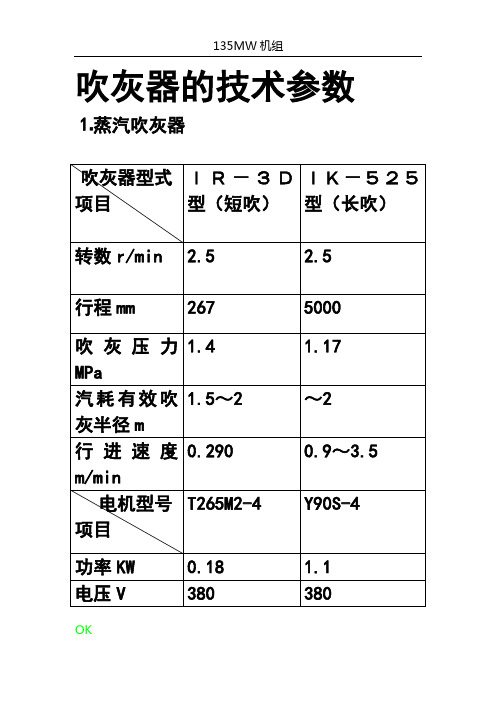
吹灰器的技术参数
⒈蒸汽吹灰器
吹灰器型式
项目
IR-3D型(短吹)
IK-525型(长吹)
转数r/min
2.5
2.5
行程mm
267
5000
吹灰压力MPa
1.4
1.17
汽耗有效吹灰半径m1.5~2来自~2行进速度m/min
0.290
0.9~3.5
电机型号
项目
T265M2-4
Y90S-4
功率KW
0.18
1.1
电压V
炉膛四壁(后墙6台,其它墙各9台)
33
蒸汽
2
伸缩式长吹灰器IK-525型
两侧墙
8
蒸汽
3
声波吹灰器
竖井烟道
12
压缩空气
4
固定喷射管式
水平连接烟道
12
压缩空气0.5~0.6MPa
5
空气预热器
空气预热器进、出口
4
蒸汽(0.93~1.07MPa)
吹灰器通用版说明书
烟气加热器GGH用全伸缩式吹灰器Jetblower 安装、运行与维修手册目录1前言 (4)2/1.吹灰设备技术数据表 (5)3吹灰设备运行要求 (8)4吹灰设备冷态调试 (9)5吹灰设备热态调试 (10)6吹灰装置日常维护和保养. (10)7吹灰器空气密封墙箱 (11)8吹灰器润滑表 (12)9吹灰器安装说明 (14)10吹灰器总体描述 (16)11内/外管组件的装配和拆卸 (20)12现场替换高压水喷嘴 (21)13Jetblower全伸缩吹灰器图 GH-0 (22)14喷嘴装配图 K22588 (23)15吹灰器本体阀门 (25)16本体阀门图GH-2-0 (30)17吹灰器电机齿轮箱 (32)18齿轮箱图 K20695 (35)19吹灰器行走箱组件 (图 K20220) (36)20高压水软管托架组件 (图见GH-8-0 GH-9-0) (37)21横轴组件 (图见K21685) (38)221”链条张紧机构(图见 K22545) (39)231/2”链条张紧机构 (见图K20217) (39)24行走箱图 K20220 (41)25高压水软管托架图GH-8-0 GH-9-0 (42)26横轴图K21685 (43)27张紧机构 K20217 K22545 (45)28编码器 (47)29密封风机 (54)30压力变送器 (59)31高压水过滤器 (71)32流量开关 (77)33ASCO 电磁阀 (78)34限位开关 (83)1前言回目录本公司生产的烟气加热器用全伸缩式吹灰器是按照正常工况条件下,采用严格的技术要求和公差控制来设计、制造的,保证吹灰器能可靠、有效地运行。
通过采用本说明书所介绍的方法对吹灰器进行定期检查和维修,定期润滑和更换密封填料能保证吹灰器处于最佳工作性能和保持工作寿命。
当吹灰器运行时,可以同时参照本说明书和所提供的组件图。
如遇到本说明书没有涉及到的任何技术问题,可按下面的地址进行联系:中国上海杨树浦路2200号上海克莱德贝尔格曼机械有限公司电话:0086-021-65396385传真:0086-021-65661886备件:我们通过精密制造来保证提供的备件具有完全互换性。
蒸汽吹灰器说明书

第一章前言1.1 概述C305-525/C305-545型长伸缩式吹灰器(图1)统称为C305-500系列长伸缩式吹灰器,二种吹灰器的行程范围不同,但其结构形式、传动原理和安装形式基本相同(图2),电气接线和控制原理(图3)也完全相同,零部件大部分通用。
C305-500系列长伸缩式吹灰器是以蒸汽或压缩空气作为吹灰介质,吹扫锅炉受热面上的积灰和结渣的吹灰器。
主要用在清除捕渣管、过热器、再热器和省煤器等部位的结灰,也可用来清除炉顶和管式空气预热器的结灰。
1.2 工作原理(1)清扫原理从伸缩旋转的吹灰枪管端部的两个或几个喷嘴中,喷出蒸汽或压缩空气持续冲击、清洗受热面是本吹灰器的工作原理。
喷嘴的轨迹是一条螺旋线。
吹灰器的运行速度、螺旋线导程(100或150或200mm)和吹灰压力等由吹灰要求决定。
吹灰器退回时,喷嘴吹扫的螺旋轨迹与前进时的轨迹错开1/2节距。
图4为两个喷嘴、100mm导程吹灰器的吹灰轨迹示意图。
(2)主要机构A、高效喷嘴——对每一台吹灰器专门选定。
B、喷嘴传送机构——吹灰枪管、跑车和电动机。
C、向喷嘴提供吹灰介质的机构——阀门、内管、填料压盖和吹灰枪管。
D、支承和包容吹灰器元件的机构——两点支吊的箱式梁。
E、控制系统——提供控制电源和动力电源,控制吹灰器的运行。
(3)吹灰过程吹扫周期从吹灰枪处在起始位置时开始(如图1)。
吹灰器启动后,电动机驱动跑车沿着梁两侧的导轨前移,将吹灰枪匀速旋入锅炉内。
喷嘴进入炉内一定距离后,跑车开启阀门,吹灰开始。
跑车继续前进,吹灰枪不断旋转、前进吹灰;直至达到前端极限后,电动机反转,跑车退回,吹灰枪管以与前进时不同轨迹后退吹灰。
当喷嘴接近炉墙时,阀门关闭,吹灰停止。
跑车继续后退,回到起始位置。
1.3 主要技术参数吹灰器行程(m)最大7.62 (C305-525)7.63~13.72 (C305-525)吹灰介质蒸汽或压缩空气进退速度(m/min) 0.9~3.5转速(r.p.m) 9~35喷嘴口径(mm) 12~32吹灰半径(m)~2吹灰角度360°吹灰压力按吹灰要求(见注)电动机型号、规格 Y90S-4 B5型 1.1kw 1400 r.p.m (C305-525) Y90S-4 B5型 1.5kw 1400 r.p.m (C305-545)电动机电源 380V 50Hz 3P近似重量参数根据锅炉、燃料及灰的特性、烟温和吹灰介质的具体情况确定。
吹灰器设计使用说明书 2
余热锅炉吹灰器使用说明编制:校对:审核:余热锅炉吹灰器使用说明一、概述催化装置余热锅炉配有一套激波吹灰系统,该系统利用乙炔及压缩空气在蓄气罐中按一定配比迅速燃烧产生脉冲激波从而有效清除锅炉受热面的积灰。
吹灰器吹灰系统的布置根据本炉结构、烟气性质,选用我公司的XSJ-JZ型燃气脉冲吹灰系统。
脉冲发生器分别布置在4个吹灰层面,共15个脉冲发生器,15个吹灰点,即:第一层在过热器布置后侧墙3台脉冲发生器,每台脉冲发生器带1只定向喷嘴;第二层在蒸发器前侧墙布置4台脉冲发生器,每台脉冲发生器带1只定向喷嘴;第三层在高温省煤器前侧墙布置4台脉冲发生器,每台脉冲发生器带1只定向喷嘴;第五层在低温省煤器前侧墙布置4台脉冲发生器,每台脉冲发生器带1只定向喷嘴;根据该炉的积灰性质和结构尺寸,在保证吹灰效果的前提下,选择的吹灰点位置和脉冲发生器的尺寸、数量见下表。
系统布置详见施工图纸。
脉冲发生器及喷嘴位置、数量、规格显示触摸屏吹灰的路数现场具体吹灰位置如下:第一路吹灰器吹灰位置在过热器东第二路吹灰器吹灰位置在蒸发器东第三路吹灰器吹灰位置在高温省煤器东第四路吹灰器吹灰位置在低温省煤器东第五路吹灰器吹灰位置在过热器西第六路吹灰器吹灰位置在蒸发器西第七路吹灰器吹灰位置在高温省煤器器西第八路吹灰器吹灰位置在低温省煤器器西二、吹灰器原理及特点脉冲激波吹灰系统吹灰机理是通过冲击动能、声能和热能作用来清除锅炉受热面的表面积灰,达到提高锅炉效率,恢复锅炉出力的目的。
脉冲吹灰器的技术原理:燃气(通常是乙炔或瓦斯)在特殊结构混配点火装置中,与空气混合,被高能点火器点燃,产生爆燃,爆燃气体受罐体内特殊结构的调制瞬间产生冲击波。
当冲击波作用于积灰表面时,其声能和动能将对灰粒子产生冲击和加速扰动,使之与受热表面分离,从而脱落。
通过对两种气体的配比浓度和蓄能量的控制生成不同形式和不同强度的冲击波,可完成不同程度、不同类型积灰的清除。
脉冲激波吹灰系统的主要特点是:冲击波将能量聚积于极短时间和空间,在气体介质中形成瞬间能量间断面,使气流的压力和速度产生突变,其瞬间传播速度为度量尺度,声压可达到160dB以上,压力通常10~15㎏/㎝2,速度可达300~350m/s。
空预器说明书
十一月份培训内容5.1.4 空气预热器:#1、#2炉空气预热器采用由上锅供货的2-29.5VI(65°)-2200(2300)正转回转式空气预热器,#3、#4炉空气预热器采用由哈锅供货的30.5-VI(T)-2400-QMR 回转式空气预热器,采用三分仓布置,经济性和可靠性较好,该空气预热器从烟气侧吸收热量,然后通过由特殊形状的金属板组成的连续转动的传热元件把热量传给空气。
高效率传热元件紧密地放在扇形仓,扇形仓在径向分隔着被称为转子的圆柱形外壳内,转子之外装有转子外壳,外壳的两端同连接烟风道相连。
预热器装有径向密封和旁路密封,形成预热器的一半流通烟气,另一半流通空气。
预热器设计漏风系数小,径向密封可以跟踪调节,使密封区在任何状况下保持最小平均间隙,为了确保预热器安全,本空预器驱动装置设有二个马达,即主马达和气动马达。
当电动马达跳闸或失去电源时,气动马达自动投入,维持转子转动,但气动马达不能长时间带负荷运行。
此外,空预器还设有吹灰器、多喷嘴水冲洗装置和消防水装置,以确保空预器的安全、稳定、经济运行。
5.2.1空气预热器规范:7.4.1支撑轴承拆卸(参见附图4):7.4.1.1利用调节装置将高温端扇形板提高约10㎜;7.4.1.2拆下下部挡水盖,清理检查调换填料;7.4.1.3拆除进、出口油管及温度计电缆;7.4.1.4将油放尽;7.4.1.5拆下轴承箱上罩壳,并做好记号;7.4.1.6将制动螺栓拆除;7.4.1.7将底盖拆除并做好记号;7.4.1.8在耳轴法兰面上用气割割除4根螺帽防松杆;7.4.1.9拆除耳轴法兰螺丝;7.4.1.10将千斤顶梁放于耳轴法兰下指定位置,临时固定于中心部分;7.4.1.11根据转子重量选择千斤顶,将千斤顶平衡地设置在千斤顶梁上,一头与耳轴法兰平面顶住。
设置好后请有关技术人员来现场检查,认为符合要求时,才能将转子顶高5㎜左右。
7.4.1.12质量标准:a)轴承滚柱表面应光滑,无斑点、裂纹、剥皮现象;b)砂架完整无损,滚柱在砂架中转动灵活;c)调节环固定螺丝不得有损伤;d)调节环结合平面应平整无纹路;e)推力轴承外壳合金钢螺丝不得有损伤;f)轴颈应光洁、平滑,不得有裂纹、凹痕、毛刺等缺陷;g)主轴法兰平面应平整、无毛刺及较严重的碰伤;h)主轴法兰螺丝应无损伤现象,各螺丝紧固力距应一致,法兰螺丝紧固后,两法兰平面应接合严密, 用0.03㎜塞尺检查,塞不进为佳;i)转子标高应检修前、后一致;j)转子中心与密封盖偏心不大于0.2㎜;k)防水密封罩壳装好后,不得有泄漏现象。