EPEC 控制器使用手册
E-CELL操作说明书

操作手册FOR THE120 GPM, 27.3 m3/hE-CELL SYSTEM TM注意:本手册含有对 E-Cell 公司所提供的水处理系统的操作和维护指导。
在操作和维修该系统时,必须始终遵守手册中的程序。
此中文文本的内容与英语版本的用户手册有分歧时,以英文版本为准。
1. 人身安全注意事项E-CELL MK-2 STACK™1.1 电气1. 定期检查接线端子是否接触良好。
2. 如发现有损坏的电气元件,在修复或更换前要先隔离该元件。
3. 检查电器箱密封良好以防进水。
4. 只允许有资格的电气技术人员进行检修工作。
5. 整流器处于工作状态时不可切断E-Cell MK-2模块上的电源线。
1.2 机械E-Cell MK-2 模块含有电器元件,可能造成触电危险,故请勿将工具、螺丝等放置在E-Cell 模块上。
除专业人员外,不要调整E-Cell MK-2 模块上的螺丝。
模块端板间的距离在出厂前已经精确调节,过度调整可能造成永久损害。
1.2.1 泄漏MK-2 模块的最大操作压力是 100 psi (6.8 bar) ,在正常压力下模块不应泄漏。
如发现模块漏水,应停机检查泄漏位置和模块端板间距。
若漏水无法解决,请立即联系E-Cell 公司。
1.2.2 离心泵1. 严禁在运转的离心泵上工作。
如需维护必须停机并在泵上加标识。
2. 确保水泵电机风扇的通风畅通。
1.2.3 水力E-Cell™ 系统通过不同管径的管道输送大量的水,如非正常的操作可能引起设备损坏、高压水泄漏以致人身伤害。
1. 确认所有的管道都有足够的固定和支撑。
2. 在开启系统进水阀门前,保证出口阀门已经开启。
1.3 停机必须遵守停机程序来保证工作人员的安全。
不仅需注意转动设备和电器,对容器或水管也应小心。
1.4 通道在 E-Cell™ 设备周围应有足够的通道和照明以便操作和维护的安全。
1.5 安全用具当可能暴露在酸碱环境中时,须穿戴橡胶手套、橡胶服、面罩和防护眼镜。
PLC控制器说明书

PLC控制器使用说明书承德承申自动化计量仪器有限责任公司本套系统适用于定量给料机,固体流量计,皮带秤。
采用了德国西门子S7-200系列PLC,具有运行稳定,精度高,扩展能力强的优点。
采用西门子大屏幕触摸屏,使的操作画面更加清晰直观易于操作。
数据输入全部采用屏幕软键盘,用户更加方便操作。
本系统可完全替代原装申克系列仪表应用的场合,其部分性能已超越原装仪表且价格低廉,扩展性能强。
以下部分是整个系统的操作解释,用户务必连续阅读。
首先是系统上电后的主画面:Array上电后触摸屏有一个自检过程过几十秒后与PLC连接成功,出现主画面。
在主画面中显示了两台给料机的工作画面。
如果此时有报警则在画面的右上角出现报警提示,用手点击报警提示,即可看到具体的报警信息。
主画面介绍:画面分为左右两台给料机,左边为一号给料机,右边为二号给料机。
我们以一号给料机为例进行介绍。
“#1启动”键用于启动给料机。
“#1停车”键用于停止给料机。
“ON/OFF”用于表示当前给料机的运行状态是处于启动状态或者停止状态下。
“G-MODE/V-MODE”用于表示当前给料机的运行模式是处于称量状态或者容积状态下。
“设定流量”表示当前给料机的设定值,用手按“设定流量”后面的数字即可出现一幅由数字和部分字母构成的屏幕键盘,在键盘上按相应的数字键和确认键即可完成对“设定流量”的修改。
(B07中的设定值为“触摸屏”时有效)“实际流量”表示当前给料机的实际流量值。
“皮带负荷”表示当前给料机的称量端负荷值。
“皮带速度”表示当前给料机的皮带速度值。
“累计流量”表示当前给料机的累计流量值。
主画面介绍完了,下面介绍功能画面:“功能键”位于主画面的左上角,点击“功能键”即可出现“功能画面”如下图:主画面介绍:“系统功能画面”分仍为左右两台给料机,左边为一号给料机,右边为二号给料机。
我们仍以一号给料机为例进行介绍。
1、标定功能:根据实际应用参数对程序进行必要的设置,以便精确的应用在实际现场中。
EPEC 2024 控制器 说明书
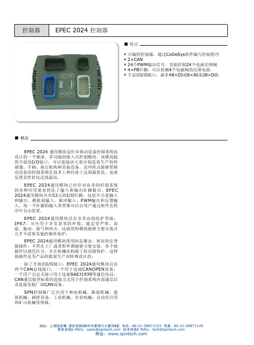
■概述EPEC 2024 通用模块是针对移动设备控制系统而设计的一个紧凑、多功能的嵌入式控制模块。
该模块提供开放的I/O接口,可以连接决大部分制造商生产的传感器、手柄、执行机构和其他设备。
这些特点能够使移动设备的控制系统在技术上和经济上达到最优化,也就是使其性价比达到最高。
EPEC 2024通用模块已经针对众多的控制系统的各种应用要求优化了输入和输出针脚数目。
EPEC 2024通用模块共有52点的I/O针脚,包括开关量输入和输出、模拟量输入、脉冲输入、PWM输出和反馈输入。
每一个针脚的输入类型都可以由用户通过软件在程序中自由设置。
EPEC 2024通用模块具有非常高的防护等级:IP67,可应用于非常恶劣的环境,能忍受严寒、高温、振动、湿气和冲击。
这就使得模块能够方便安装并几乎不需要其他的额外保护。
EPEC 2024通用模块使用的是镀金、密封的安普接插件,不管在工厂或者野外都能够方便安装。
各个接插件以颜色区分,并在机械结构做了防误插保护。
这种接插件是为产品的批量生产而特殊设计的。
除了开放的I/O接口,EPEC 2024通用模块具有两个CAN总线接口,一个用于连接CANOPEN设备,一个用户自定义接口用于连接SAEJ1939等通信协议。
CAN通信提供标准的连接方式用于控制系统内部通信以及连接其他厂商CAN设备。
SPN控制器广泛应用于林业机械、路面机械、建筑机械、破碎设备、工业机械、农业机械、自动化应用和矿山机械等领域。
■技术参数■控制器经过测试■ I/O配置I/O说明简介,详细请参考EPEC 2024用户手册内部电路原理图■ 电气特性■电气特性注释1 :超过最大值会导致输入点损坏内部电路原理图■ PWM频率控制分组■ DI/DO/PWMXM1.1 XM1.2 XM1.3 XM1.4 XM1.7 XM1.8 XM1.14 XM1.15 XM1.16 XM1.17 XM1.22 XM1.23 XM2.1 XM2.2 XM2.5 XM2.6 XM2.7 XM2.8 XM2.9 XM2.10 XM2.16 XM2.17 XM2.22 XM2.23■电气特性■电气特性■电气特性■ 电气特性地址:上海陆家嘴 浦东南路256号华夏银行大厦704室 电话:86-21-58871153 传真:86-21-58871140商务咨询E-MAIL :*****************技术咨询E-MAIL :****************网址:●2只M6螺钉(DIN912标准)●垂直或水平安装,如上图● 关于模块安装的详细信息请参考用户手册中模块的安装和接线说明。
PLC可编程控制器 使用说明书
起火能导致其运行时散热不畅,引起火灾、故障、
误操作。 安装和接线必须牢固可靠,接触不良可能导致误动作。 设备外部配线的规格和安装方式应符合当地配线法规要求, 详见本手册配线章节。 模块顶部有防止异物进入的标签, 防止配线期间配线头等异物进入模块, 配线期间请勿
1.2.1 可编程控制器工作原理............................................................................................... 6 1.2.3 用户程序控制原理....................................................................................................... 6 1.3 编程语言.................................................................................................................................. 6 二、产品规格.........................................................................................................................................7 2.1 产品命名规格......................................................................................
EPEC 软件库使用手册_V1.0

4)Output 数据类型: UINT 1.5.HP 模块
HP模块用于设定死区。
上海派芬自动控制技术有限公司 地址:上海·浦东·金桥浙桥路 289 号建银大厦 A 座 605~608 邮编:201206
5)Output 数据类型: UINT
6)PosValue 数据类型: BOOL PAR_Zero * 256 > Input值,值为 TRUE;PAR_Zero * 256 < Input 值,值为 FALSE。
2 .PWMControlvoltageAmpere -funktio库: 2.1.Motion 模块
数据类型: BOOL 3) DI_JoystickDirSwitchNEG负向微动开关
数据类型: BOOL 4)OutputEnable(同上) 5)PAR_NegFull
上海派芬自动控制技术有限公司 地址:上海·浦东·金桥浙桥路 289 号建银大厦 A 座 605~608 邮编:201206
电话:+86-(21)-51303669/70 传真:+86-(21)-51303671 tech@
3)PAR_PosFull 数据类型: UINT 当input值>=PAR_PosFull * 256时, 输出为65535 , PosValue 为TRUE。
4) PAR_NegFull 数据类型: UINT 当input值<= PAR_NegFull * 256, 输出为-65535 ,PosValue 为 FALSE。
EPEC 软件库使用手册_V1.0
EPEC 2024 数据手册新版

Epec 2024 Control ModuleTechnical DocumentDocument: 2024G08Updated: 1.10.2008Epec Oy reserves all rights for improvements without prior noticeDOCUMENT VERSION HISTORYDate Notes1.10.2008Document and layout updated 16.8.2006First released versionEpec Oy reserves all rights for improvements without prior noticeTABLE OF CONTENTS1 GENERAL (4)1.1 Purpose of This Document (4)1.2 About Manufacturer (4)1.3 Epec CAN Module Family (4)1.4 Basic skills required (4)1.5 Safety guidelines (4)1.6 Warranty (5)1.7 Limited liability (6)1.8 Environmental statement (6)2 I/O MODULE GENERAL DESCRIPTION (7)2.1 Programming Environment (7)2.1.1 Codesys 2.1 (7)2.1.2 Codesys 2.3 (8)2.2 CANopen Indexes (8)3 INPUT / OUTPUT SPECIFICATIONS (9)3.1 Configurable I/Os (9)3.2 Digital Input (10)3.3 Current Measuring Feedback (11)3.4 Digital Input / PWM Output / Digital Output (12)3.5 Digital Input / Analog Input (15)3.6 Digital Input / Digital Output (sinking) (17)3.7 Digital Input / Pulse Input (19)3.8 Specification for Internal Diagnostics (21)3.9 Closed Loops Wiring (21)3.10 I/O / IEC Map (22)3.11 AMPSEAL Connectors (23)3.12 AMPSEAL Cable Dimensions (23)4 POWER SUPPLY (24)4.1 Overvoltage Protection (24)4.2 Power Consumption (24)4.3 Power Supply Pins (24)5 BUS CONNECTION (25)5.1 Bus Connection Pins (25)5.2 CAN Interface (25)6 ENVIRONMENTAL CHARACTERS (26)6.1 Protection (26)6.2 EMC Tests (26)6.3 Environmental Tests (30)7 HOUSING (32)7.1 Mounting (32)7.2 Unit Dimensions (33)8ADDITIONAL DOCUMENTS (34)Epec Oy reserves all rights for improvements without prior notice1 GENERAL1.1 Purpose of This DocumentThis technical document is meant to be used in system development. This document containsnecessary data concerning the module in question, which system designer needs in systemdevelopment work.Copying of this document without permission is prohibited. All trademarks mentioned in thisdocument are owned by their manufacturers.1.2 About ManufacturerEpec Oy helps its customers to manufacture efficient, safe and environmental friendly mobileworking machines and special vehicles which help their customers to maximise theirproductivity.Epec is a solution provider specialized in embedded control systems, vehicle computers andinformation logistics systems for mobile machines. We believe that we know control systems forchallenging conditions and we are able to offer a total solution from control units to projectservices and designing.1.3 Epec CAN Module FamilyEpec CAN Module Family is designed to operate in extreme environments, where vibration,wide temperature changes and moisture are normal conditions. The requirements for thesystem’s reliability and safety have been the key words in module family development. A smalland protective module casing keeps inside high performance microcontroller with lots of controlcapabilities.1.4 Basic skills requiredThe user of this document must have professional skills on machine controlling, CANcommunication, PLCopen programming according to IEC61131-1 and should have skills to useCoDeSys 2.1/2.3 programming environment.Please refer CoDeSys 2.1/2.3 manual for further information on programming environment andrequired installations.Please refer CAN and CANopen documentation from CAN in Automation (CiA) for furtherinformation on communication issues.1.5 Safety guidelinesThe user of this documentation should follow general machine safety guidelines, directives andregulation appropriate to his/her country or market area.This product does not comply with SIL2 or SIL3 classifications and should not be used in suchapplications, e.g. lifting people, where SIL 2 or SIL3 are required by directives or otherregulations.A separate safety analysis is always recommended for the machine and its control system. Thefeatures of this product should be well documented in machine and control system documentsEpec Oy reserves all rights for improvements without prior noticeso that the machine operator has the right information how to operate the machine correctly andsafely.This product is designed to be used only for machine controlling purposes. The manufacturerdoes not assume any responsibility for this product being fit for any particular application, unlessotherwise expressly stated in writing by the manufacturer.This product complies with those certifications and standards that are listed below. Themanufacturer does not guarantee that this product complies any other certification, standard ortest than listed below.This product is not field serviceable, so it should not be opened at any situation.An external fuse should be installed for the product or the system power supply.The system should be designed and constructed according to the Epec general mounting andcabling instruction document.Epec Oy reserves a right to improve its products without a further notice.1.6 WarrantyThe manufacturer does not assume any responsibility for the products being fit for any particularpurpose, unless otherwise expressly stated in writing by the manufacturer.The manufacturer gives the warranty of twelve (12) months to the products and thereto relatedfirmware from commissioning or eighteen (18) months from the date of delivery of the productswhich ever occurs firstThe manufacturer is during the warranty period responsible for defects in the products andthereto related firmware resulting from faults in material, design or workmanship. Themanufacturer’s only obligation under this warranty is to, at its sole discretion, either to replacethe products and/or thereto related firmware or to repair the defective products. Themanufacturer shall, at its sole option, repair the products at its manufactory in Seinäjoki,Finland.The warranty does not cover any costs related to removing or fastening of devices related to theproducts. Neither does the warranty cover the expenses of sending devices to or from themanufacturer for repairs. The warranty does not cover possible expenses relating to travelling,accommodation, daily benefits, etc. of installers.The warranty becomes null and void if the buyer and/or a third party alters the products or thefirmware in any way or if they are not used in accordance with the Manufacturer’s operatinginstructions.All claims with respect to defects in the products shall be made to the manufacturer withoutdelay and no later than on the seventh (7th) day after the defect has been or should have beendiscovered by the buyer. The manufacturer strives to reply to the claim in writing within two (2)weeks from the receipt of the claim. The buyer shall attach to the claim a possible error report orequivalent explanation of the grounds for the claim.The manufacturer gives no other warranties whatsoever for the products than the warranty setout in this section and thus the warranty given in this section sets forth the warranty given by themanufacturer in its entirety.Epec Oy reserves all rights for improvements without prior notice1.7 Limited liabilityThe manufacturer shall under no circumstances be liable for loss of production, loss of profit,loss of use or any other consequential damages and/or indirect losses, whatever their causemay be. In case claims based on product liability are brought against the Manufacturer for whichclaims the manufacturer may be liable, the manufacturer’s liability is limited to the extentnormally covered under normal product liability insurances.The buyer shall compensate the manufacturer to the extent that the manufacturer might beliable to pay damages as a result of claims based on product liability according to paragraphabove.1.8 Environmental statementThe manufacturer uses ISO14001 environmental certified processes and materials tomanufacture products. The manufacturer undertakes to arrange for the recycling and scrappingof the products that are returned to the manufacturer by the buyer and/or the products that arereceived by the Manufacturer in connection with maintenance services performed as a result ofthat repairing of the products is deemed by the manufacturer to be inappropriate.The manufacturer will charge a scrapping fee from the buyer according to the manufacturer'sprice list in force from time to time. No scrapping fee will, however, be charged for products thatare received by the manufacturer during the warranty period.Epec Oy reserves all rights for improvements without prior notice2 I/O MODULE GENERAL DESCRIPTIONI/O Module is part of the Epec CAN Module Family. I/O Module has large amount of digital andanalog inputs and digital outputs. Digital outputs can be configured to be used as digital inputs and vice versa. Module is used in a CAN control module system as a multifunction controller with different kinds of sensors and actuators, such as proportional valves, servo motors, andelectro-hydraulic components. This PLCopen programmable (with CoDeSys tool) module canalso be used as an independent controller because of digital and analog I/O capabilities. I/OModule has two CAN-busses.FeaturesApplications • ISO High Speed CAN1 interface• ISO High Speed CAN2 interface• Operating voltage 10 - 30 VDC• Recommended operating voltage 24 VDC• Overvoltage protection• Overheating protection• Short-circuit protection for outputs• Gold plated, locked and sealed connectors:8-pin AMPSEAL for module connection3 x 23-pin AMPSEAL for I/O• Small outline dimensions: 147 x 113 x 46• Weight 0,7 kg• Forest Machines • Road Maintenance • Construction Machines • Crushing Stations • Industrial Machines • Agricultural applications • Automation applications • Mining MachinesMonitoring FunctionsFollowing issues can be monitored by the application• Supply voltage• Firmware/application code corruption• Module temperatureSoftware deadlock is monitored by the hardware watchdog that reboots the moduleautomatically after 300 ms software deadlock.2.1 Programming EnvironmentThis product can be programmed with either CoDeSys 2.1 or CoDeSys 2.3 depending on themodule’s firmware. If the firmware’s runtime is older than 2.1x, the programming environment isCoDeSys 2.1 and if the runtime is 2.3.x or newer the programming environment is CoDeSys2.3.The runtime version can be checked from index with a CANopen tool, for example withCANmoon.2.1.1 Codesys 2.1• Flash• 248 x 16-bit flash saved parameters (Runtime older than 2.15)• 756 x 16-bit flash saved parameters (Runtime 2.15 or newer)• CAN buses• Supported baud rates 20, 50, 100, 125, 250, 500 and 1000 kbit/s.• CAN1• CANopen• CAN2• User programmable• J1939Epec Oy reserves all rights for improvements without prior notice• Pulse inputs• Maximum pulse input frequency 20 kHz.• Joint frequency for all pulse inputs. (e.g. four channel in use --> 5 kHz for each channel.)• Minimum PWM frequency• 40 Hz for 20 MHz module• 80 Hz for 40 MHz module2.1.2 Codesys 2.3• Flash• 6200 bytes flash saved parameters.• 10 separately saved sets.• Maximum code size 254 kb.• CAN-buses• User programmable CAN for all physical CAN-buses• Supported baud rates 50, 100, 125, 250, 500 and 1000 kbit/s.• Supported protocols• CANopen (for all physical buses)• J1939 (only for one bus in the same module)• ISOBUS (only for one bus in the same module)• Possible to add external c-programmed library• Minimum PWM frequency• 40 Hz for 20 MHz module• 80 Hz for 40 MHz module• Maximum pulse input frequency 40 kHz. Joint frequency for all pulse inputs. (e.g. fourchannel in use --> 10 kHz for each channel). Is dependable for the other interrupt load inmodule (for example heavy CAN-traffic can reduce maximum frequency).2.2 CANopen IndexesCANopen communication features can be installed through software, for example NodeIDs andCAN rates. For more information refer to programming manuals.Epec Oy reserves all rights for improvements without prior notice3 INPUT / OUTPUT SPECIFICATIONSI/O module contains inputs and outputs or, in other words, I/O pins of many different types.There are, for example, outputs which source current and outputs which sink current.Furthermore, there are I/O pins which can be used as inputs or as outputs at the control of theapplication programmer.3.1 Configurable I/Os DI AI PI DO PWMMax Amount Digital Input Analog Input Current Measuring Feedback Pulse Input Digital Output (sourcing) Digital Output (sinking) Pulse Width Modulation Output4 x4 x24 x x x8 x x4 x x8 x x52 48 12 8 28 24The usage of each I/O pin is determined by the application.Epec Oy reserves all rights for improvements without prior notice3.2 Digital InputPins X1.19, X1.20, X2.19, and X2.20 are ground referenced inputs (DI ).Pins are associated with a bit variable in the IX area in PLCopen programming environment.The application program will see there a logical zero when the pin is grounded or left open anda logical one when the pin is connected to a positive voltage source.Electrical Characteristics Symbol Parameter ConditionsMin Max Units V I Greater than 4,3 V (Note 1)9,0 11 k Ω R I Input Resistance Referenced to 1,3 V;V I Less than 4,3 V (Note 1)6,2 7,6 k Ω V IH Input High Voltage4,8 30 V V IL Input Low Voltage-0,5 4,2 V t C=10 ms (Note 2, 3, 4, 5) 12 Hz f I Input Frequency Variable t C (Note 2, 3, 5)1/8t CC I Input Capacitance 37 57 nFNote 1: With input voltages below 4,3 V it seems like the internal input resistance wasconnected to a 1,3 V voltage source.Note 2: t C denotes software cycle time.Note 3: Violating this rating may lead to system not recognizing all input state transitions.Note 4: These parameters depend on software cycle time.Note 5: Applies to inputs used as normal digital input. Violating this rating may lead toapplication program not noticing all input state transitions.Connection PrincipleEpec Oy reserves all rights for improvements without prior notice3.3 Current Measuring FeedbackPins X1.5, X1.6, X2.3, and X2.4 are normally used as a return path for the loads of PWM outputs. These kinds of pins have a small shunt resistor connected to ground. The shunt resistor is used to measure the current flowing through the load. Nothing prevents using these pins to measure currents from other sources as well.In PLCopen programming environment, there is a word variable in IW area associated with each pin from where the software can read the actual current flowing into the pin.Electrical Characteristics Symbol Parameter ConditionsMin Max Units R I Input Resistance0,21 0,23 Ω Analog measuring range 0,0 1,0 A I I Input Current (Note 1) 1,7 A TIRETotal Input Referred Error55mANote 1: Exceeding the max value might cause damage to input.Connection PrincipleA pin where the upper wire of the load is connected is PWM output / digital output. This illustrates the normal way to connect loads when load current measurement is desired.Epec Oy reserves all rights for improvements without prior notice3.4 Digital Input / PWM Output / Digital OutputThese pins are current sourcing outputs. In other words, pin connects the load to positive supply voltage. The application program can also simultaneously monitor the actual state of the pin. This feature makes it possible to detect short circuits to the ground. Open loads can not be detected because the internal load resistor is connected to the ground.Connector X1 Connector X2X1.1 X1.2 X1.3 X1.4 X1.7 X1.8 X1.14 X1.15 X1.16 X1.17 X1.22 X1.23 X2.1 X2.2 X2.5 X2.6 X2.7 X2.8 X2.9 X2.10 X2.16 X2.17 X2.22 X2.23These kind of outputs are also capable to generate pulse width modulated (PWM) output signals. This feature is useful when driving proportionally controlled loads, e.g. proportional hydraulic valves. Monitoring the state of the pin is generally not possible when the pin is used as a PWM signal output.PWM frequencies can be configured under software control in groups of outputs. The frequency is set by HW_SET_PWM_FREQ function call. The setting is done by a PWM channel but setting the frequency of one channel sets also the frequencies of all the other channels in the same groups.In very carefully selected applications a pin of this type can also be used as an input by using the output state monitoring feature. In those cases, the output functionality of the pin must of course be kept in off state. It must be taken care in system design that the output unintentionally switching to on state causes no harm to the system.Epec Oy reserves all rights for improvements without prior noticePWM Frequency Control Groups (PFCG)Group Channel Output pin 0 X1.231 X1.22 2 X1.173 X1.164 X1.15 X1.26 X1.47 X1.38 X2.29 X2.1 10 X2.9 A 11 X2.10B 12 X2.8C 13 X2.7D 14 X2.6E 15 X2.5 16 X1.717 X1.8 18 X1.15 19 X1.14 20 X2.17 21 X2.16 22 X2.22 F 23 X2.23Electrical Characteristics Symbol Parameter Conditions Min Max Units R O Output Resistance Output On 0,2 Ω I O Output Current Output On 3 A f PWM PWM Frequency (Note 1)40 2550 Hz Group A and F (Note 1) 2,5 MHz/ f PWM Group B, C, D and E (Note 1)312,5 kHz/ f PWMGroup A and F;f PWM =100 Hz (Note 1) 25000PWM Resolution Group B, C, D and E; f PWM =100 Hz (Note 1)3125R I Input Resistance Output Off 2,8 7,5 K ΩV IH Input High Voltage 3 V IN V V IL Input Low Voltage Output Off-0,5 1 V t C =10 ms (Note 2, 3, 4)12 Hz f I Input frequencyVariable t C (Note 2, 4) 1/8t C t C =10 ms (Note 2, 3, 4)40 ms t I Input Pulse WidthVariable t C (Note 2, 4)4t CEpec Oy reserves all rights for improvements without prior noticeConnection PrincipleA pin where the lower wire of the load is connected is current measuring feedback. This illustrates the normal way to connect loads when load current measurement is desired.Connection Principle (when used as an input)PWM capable outputs are divided into six groups.Note 1: All outputs in the same group shareizing all input state transitions oftware cycle time Note 4: t C denotes software cycle timethe same PWM frequency (default value 140 Hz) Note 2: Violating this rating may lead to system not recogn Note 3: These parameters depend on sEpec Oy reserves all rights for improvements without prior notice3.5 Digital Input / Analog InputPins X1.12, X2.12, X3.5…X3.8, X3.13, and X3.14 are analog inputs. Some of the inputs are grouped: X3.5, X3.6 and X3.7 is defined as group one, and X3.13 and X3.14 is group two. Both groups can be configured either as a current input or as a voltage input. For example, if group two is configured as a current input, then both pins X3.13 and X3.14 can only be used as a current input.Pins of this kind are used to measure analog signals. They can be used as high impedance voltage inputs for signals from 0 to 5 volts or low impedance current inputs for signals from 0 to 22,7 milliamperes. Pins of this kind can be used as e.g. joystick connection when 41 k +2,5 V (voltage input) is selected.Inputs are divided into groups by the input impedance configuration. The input impedance of each group is controlled by a bit in an Input Impedance Configuration Register (IICR). This register is invisible to the programmer but it can be written by HW_SET_AI_TYPE function call.When an input like this is configured as a low impedance current input, it can’twithstand the normal maximum input voltage rating. The maximum rating is lowered in this case to 15 volts.In PLCopen programming environment, there is a word variable in IW area associated with each pin from where the software can read the actual signal magnitude at the pin.In carefully selected applications these pins can also be used as digital inputs. Generally, it is not recommended. In high impedance voltage input configuration they have low threshold voltage which is quite sensitive to interference signals. In low impedance current input configuration they are subject to damage if they are connected to for example 24 volt system voltage. There are bits in IX area associated with these inputs to support the DI functionality.Input Impedance Configuration Register (IICR) Bit Input Group IICR.0 X1.12 IICR.1 X2.12 IICR.2 X3: 5, 6, 7 IICR.3 X3.8 IICR.4 X3: 13, 14Epec Oy reserves all rights for improvements without prior noticeElectrical CharacteristicsSymbol Parameter Conditions Min Max Units V I Input Voltage Analog measuring range 0,0 5,0 V I I Input Current Analog measuring range 0,0 22,7 mA(Note 1) 2,0 30 VV IH Input High Voltage(Note 2) 2,0 15 VV IL Input Low Voltage -0,5 1,0 V I IH Input High Current (Note 2) 9,0 27 mA I IL Input Low Current (Note 2) -2,3 4,5 mAReferred to 2,5 V (Note 1) 40 42 k ΩR I Input Resistance(Note 2) 215 225 Ω0,25 VTIRETotal Input Referred Error (Note 2) 1,1 mA πI Time Constant of InputLow Pass Filter (Note 1) 3,1 4,7 msConnection Principle; High Impedance Voltage InputNote 1: Input Configured for Voltage Measurement (220 Ω Input Resistor Disconnected) Note 2: Input Configured for Current Measurement (220 Ω Input Resistor Connected)Epec Oy reserves all rights for improvements without prior notice3.6 Digital Input / Digital Output (sinking)Pins X1.18, X1.21, X2.18, and X2.21 are current sinking outputs. In other words, pins connect the load to the ground. The application program can also simultaneously monitor the actual state of the pin. This feature makes it possible to detect open loads and short circuits to the supply voltage.In very carefully selected applications a pin of this type can also be used as an input by using the output state monitoring feature. In those cases, the output functionality of the pin must of course be kept in off state. It must be taken care in system design that the output unintentionally switching to on state causes no harm to system.There are two bit variables associated with each pin of this type in PLCopen programming environment. The first is one of the QX output bits for controlling the pin as an output. The second is one of the IX input bits for monitoring the actual state of the output or reading the pin as an input.Electrical Characteristics Symbol Parameter ConditionsMin Max Units R O Output Resistance Output On 0,12 Ω I O Output Current Output On 3 A R I Input Resistance Output Off 9 11 k Ω V IH Input High Voltage Output Off 3,0 30 V V IL Input Low Voltage-0,5 1,0 V t C=10 ms (Note 1, 2, 3)12 Hz f I Input frequency Variable t C (Note 1, 3) 1/8t C t C =10 ms (Note 1, 2, 3)40 ms t I Input Pulse WidthVariable t C (Note 1, 3)4t CConnection PrincipleEpec Oy reserves all rights for improvements without prior noticeConnection Principle (when used as input)Note 1: Violating this rating may lead to system not recognizing all input state transitions Note 2: These parameters depend on software cycle time Note 3: t C denotes software cycle timeEpec Oy reserves all rights for improvements without prior notice3.7 Digital Input / Pulse InputPins X3.16…X3.23 are ground referenced inputs (DI ) including pulse counting (PI ) feature. These pins have 10 k Ω resistor connected to GND.The application program is provided with frequency and number of the pulses seen in the input in addition to the normal input state.There are three variables associated with each pin of this type in IEC programming environment. The first is a bit variable in the IX area just in the same way as with the pins without the PI features. The other two are word variables in the IW memory area which hold the frequency value and the number of pulses.After starting up the module measures only the pulse frequency. Pulse counting, if needed, must be enabled explicitly by the application program.The pulse counting competes with the application program and other processes for the CPU time. This makes it rather hard to estimate the actual maximum frequency of the pulses that the module is able to count reliably. The maximum frequencies given in the table below are such frequencies which make the module to freeze in practice if all inputs are connected to their maximum frequencies. It means that to be able to reach the maximum frequencies, there is no room for application program or any other processes like CAN traffic. So, the practical limits are lower but the maximum values of the table still give the basis for the estimation.Inputs of this type are also suitable for quadrature sensor position counting. Any of these inputs can be logically paired with another similar input. The result is a two channel pulse counter which is capable of detecting the direction of the movement of the sensor. The pairing is done in application program.The pulse count and pulse frequency can be read from the pulse input channels. The following table shows the IW-addresses where to read the wanted data (when using CoDeSys 2.1).Pulse Input channels ChannelPinPulse FrequencyPulse Count0 X3.23 %IW150 %IW160 1 X3.17 %IW151 %IW161 2 X3.16 %IW152 %IW162 3 X3.20 %IW153 %IW163 4 X3.19 %IW154 %IW164 5 X3.18 %IW155 %IW165 6 X3.22 %IW156 %IW166 7 X3.21%IW157%IW167For more information on pulse input channels refer to Hardware Library manual (HW lib).Epec Oy reserves all rights for improvements without prior noticeElectrical Characteristics Symbol ParameterConditionsMin Max Units V I greater than 4,3 V (Note 1)9,0 11 k Ω R I Input Resistance Referenced to 1,3 V;V I less than 4,3 V (Note 1)6,2 7,6 k Ω V IH Input High Voltage 4,8 30 V V IL Input Low Voltage-0,5 4,2VGroup A: X3.23, X3.17, X3.16, X3.20 (Note 2, 3, 6) 5 kHz Group B: X3.19, X3.18, X3.22, X3.21 (Note 2, 3, 6)2,5 kHz Input Frequency(frequency measurement and pulse counting) Sum of the frequencies of all theabove pins (Note 2, 3, 6)40 kHzt C =10 ms (Note 3, 4, 5, 7) 12 Hz f I Input Frequency (normal inputs) Variable t C (Note 3, 5, 7)1/8t C Note 3, 650 µs t C =10 ms (Note 3, 4, 5, 7)40 ms t I Input Pulse Width Variable t C (Note 3, 5, 7)4t CC I Input Capacitance0,8 47 nFConnection PrincipleNote 1: With input voltages below 4,3 V it seems like the internal input resistance wasconnected to a 1,3 V voltage source Note 2: All conditions must be respected. Even if some of the inputs were not used forfrequency measurement or pulse counting, these conditions must nevertheless be respected regarding those inputs too. Otherwise operation of other inputs may be interfered Note 3: Violating this rating may lead to system not recognizing all input state transitions Note 4: These parameters depend on software cycle time Note 5: t C denotes software cycle timeNote 6: Applies to inputs used for frequency measurement and pulse counting. Violating thisrating may lead to incorrect measurement or counting Note 7: Applies to inputs used as normal digital inputs. Violating this rating may lead toapplication program not noticing all input state transitions。
热泵控制器使用说明书(v2.0)
热泵控制器使用说明书:一、检测功能:模拟量:室外井水进水温度、井水出水温度、室内循环出水温度、循环进水温度和室内环境温度、室外环境温度。
开关量:室外井水水流开关、室内循环水水流开关、热泵故障。
这三个开关量均应为常开无源触点,动作时触点闭合。
二、控制输出:室外井水泵控制、室内循环泵控制、热泵控制、加引水控制、制冷控制、热泵自加热控制等6路开关量输出,其中室外井水泵控制、室内循环泵控制、热泵控制具有公共控制输入端(L),加引水控制、制冷控制、热泵自加热控制各自独立输出。
三、控制功能1、设置参数:室温、制热/制冷、室内循环出水上限、室内循环出水下限、室温偏差、当前年、月、日、时、分、秒、星期等。
2、制热控制:⑴当实际室内温度<设定室内温度—偏差值,且室内循环出水温度<室内循环出水温度低限时,能够开始制热功能,首先控制井水泵启动,延时后控制室内循环泵启动,若在室内循环泵启动后30秒内井水水流开关和室内循环水水流开关均能够闭合,则能够顺利启动热泵。
若井水水泵启动后2分钟内检测不到井水水流开关闭合,会控制“加引水”开关闭合5秒钟,给室外井水泵加引水,若10分钟仍旧不能检测不到井水水流开关闭合,则停止室外井水泵和室内循环泵工作,液晶提示“室外井水故障”,需检查排除故障后,重新给设备送电后运行。
若运行过程中检测到热泵故障信息,则顺序停止热泵、井水泵和循环泵,液晶提示“压缩机故障”,需检查排除故障后,重新给设备送电后运行。
⑵当实际室内温度>设定室内温度+偏差值,或室内循环出水温度>室内循环出水温度上限时,顺序停止热泵、井水泵和循环泵工作,停止制热工作。
⑶当室外环境温度<4℃且室内循环进水温度<4℃时,自动启动压缩机自加热。
⑷在每天5:00~8:00、17:00~22:00,室内温度控制按照设定室内温度+0.5℃运行。
3、制冷控制:当通过按键设置为“制冷”状态时,制冷控制开关闭合。
消防泵控制器使用说明书
电动消防泵控制器使用说明书一、概述:电动消防泵控制器是依据国标GB21208-2007、针对国消防泵使用的实际情况开发的一种专用、智能型控制器。
二、功能特点:1.功能描述1.1 系统状态的实时显示:当前使用的电源类型、泵状态、电压状态、电流状态以及后备电源类型;1.2 参数可设置:过压、欠压、系统密码、消防泵参数、ATSE自复延时时间、消防泵自动停止时间、消防泵类型、后备电源类型、时间日期、周测试时间等可以同过面板上的按键进行设置;1.3 系统故障报警:当出现过压、欠压、断相、错相、堵转、ATS切换失败、通信失败、泵状态异常等故障时,通过显示屏界面实时提示、蜂鸣器鸣叫、声光报警器以及led灯点亮的方式进行报警;1.4 周测试功能:设定好测试时间后,系统自动每周测试一次消防泵,并可自动判别消防泵能否正常启动;1.5 电源切换功能:当一路电源出现故障时,自动切换到另一路电源;1.6 实时采集、显示常用和备用电源的三相电压及干路电流;1.7 泵异常情况处理:能自动识别泵异常启动、异常停止;1.8 泵的紧急启动和紧急停止功能:出现紧急情况时,可对消防泵进行紧急启动和停止;1.9 泵的启动互锁:泵手动启动或紧急启动时,系统在软件和硬件上采用了互锁控制,保证任何时候只有一个泵运行;1.10当发生过载、堵转或短路情况时,系统会按照标准要求进行保护;1.11日历功能:显示当前的时间,并可随时修改;1.12 具有远程启动和远程报警功能。
1.13 具有软件复位功能;1.13 带有485通信接口,可通过该通信接口对各参数进行设定和修改,也可进行远程监测和控制(此功能有待完善)。
2.特点2.1通过高亮的LED灯显示故障,保证火灾发生时,人能在烟雾中清楚识别;2.2系统操作有A、B两种操作级别,手动和外部操作等A操作级别高于自动操作等B操作级别;2.3控制发电机的继电器与常用电源联锁,保证常用电源出现故障后,系统自动启动发电机;2.4控制器外部装有手柄和按钮,操作人员可以很方便的进行柜外操作;2.5自动定期检测消防泵和线路的好坏,可有效保证火灾发生时不出现泵不能启动的情况;2.6清晰迷离的人机界面,采用192*64大屏幕液晶中文显示,设置参数可以很方便的通过按键进行操作;2.7采用AC23级别的隔离开关,可在柜外进行带电操作;2.8各继电器的输出和开关的接线进行了互锁设计,保证不会同时启动两台消防泵;2.9控制器采用特种电线进行接线,使控制柜具有体积小、结构紧凑、安装方便、电线使用寿命长等特点;2.10采用电机保护型的断路器,对泵出现的短路故障能进行实时保护;2.11时间日期的设置能自动判断是否越界;2.12柜外装有模拟开关,可方便地演示控制器的电源切换功能;2.13火灾发生时,自动退出测试模式,保证了“消防优先”的原则;2.14大功率消防泵可以采用降压启动的方式,减小泵启动时对电网的冲击;2.15只需简单地更换直接启动或降压启动装置,就可实现消防泵控制器两种启动方式的转换三、主要技术指标:1.符合标准GB16806-2006 消防联动控制系统GB21208-2007 低压开关设备和控制设备-固定式消防泵驱动器的控制器2.设定技术参数说明:ATSE切换延时时间:两路电源均正常时,从备用电源切换到常用电源的延时时间;泵自动停止时间:泵自动运行后,自动停止所需的延时时间;3.主要器件参数4.其他参数工作电源:三相四线制,相电压AC220V MCU控制部分电源功耗:<1W工作温度/存储温度:-5℃~45℃液晶分辨率:192*64防护等级:IP31二次电流输入:5A/2mA四、安装接线:1、安装注意事项1.1电气环境■外部接线时,注意强电信号与弱电信号分开走线;■输入电源的电压波动围必须小于仪表的容限,尤其是在用户定制电源的情况下;1.2气候环境■周围环境没有滴水,气温不超过-5℃~45℃,且24h平均温度不超过+35℃;■安装地点海拔不超过2000米;■当水压驱动控制器用于户外时,管道中的水温不低于+4℃;■相对湿度<90%;1.3运输与存储环境■本产品运输时,需在包装条件下进行,运输和拆封过程中不应收到剧烈震动和冲击。