8模拟输入通道
8位数模转换器ADC0809实验报告
8位数模转换器ADC0809实验报告实验目的:本实验旨在通过使用8位数模转换器ADC0809来将模拟信号转换为数字信号,并输出至LED灯中,以达到理解数字信号的目的。
实验原理:ADC0809是典型的8位数模转换器,它是一种具有8个模拟输入通道的典型ADC。
ADC0809是一种串行转换器,它可以实现单端和差分两种模式的转换。
ADC0809的转换精度为8比特,转换速率为100厘秒。
ADC0809通过8个输入通道将模拟信号转换为数字信号,并通过8个数据引脚输出数字信号。
实验器材:电脑、ADC0809、LED灯、电阻、电容、按键开关、电源、实验板。
实验步骤:1.将ADC0809插入实验板上。
2.将电阻连接至ADC0809的引脚,以使引脚与电阻的连接具有正确的阻值。
3.将电容插入ADC0809的引脚,并连接至电源。
4.将按键开关插入ADC0809的引脚,并连接至电源。
5.将LED灯连接至ADC0809的引脚,并连接至电源。
6.将实验板接入电源,启动电路。
7.按下按键开关,开始信号转换。
8.数字信号转换完成后,将数字信号输出至LED灯中。
实验结果:本实验成功地将模拟信号转换为数字信号,并将数字信号输出至LED灯中,达到了理解数字信号的目的。
结论:通过本实验,我们可以了解数字信号的基本原理和用途。
通过使用ADC0809将模拟信号转换为数字信号,并输出至LED灯中,我们可以更好地理解数字信号的应用和意义。
同时,该实验也为我们打下了更深入学习数字电路和信号处理技术的基础。
模拟量输入通道的组成

AIN0 AIN1 AIN2 AIN3 AIN4 AIN5 AIN6 AIN7 AIN0 AIN1 AIN2 AIN3 AIN4 AIN5
CHSEL
8D CLK GND
+12V -6V
VDD VEE A B
0 1 2 3 4 5 6 7
10KΩ +5V
74HC138 A/D 转换器
+12V -6V
C INH OUT VSS VDD VEE A B C
采样/保持器的工作原理
当开关K闭合时,输入信号通过电阻向电容C充电,使输出 跟随输入变化此时为采样状态;要求充电时间越短越好,
以使电容电压迅速达到输入电压值。
当开关K断开时,由于电容具有一定的容量,仍能够使输 出保持不变,此时为保持状态;电容维持稳定电压的时间 越长越好,电容容量的大小将决定采样/保持器的精度。
控制字 40H 41H 42H 43H 44H 45H 46H 47H
1
1 1 1 1 1 1 1 1 1 1 1 0 1 1 1 1 1 1 1 1 1 1 1 G1 74HC138
0
0 0 0 0 0 0 0 0 0 0 0 1 0 0 0 0 0 0 0 0 0 0 0 C
0
0 0 0 0 0 0 0 1 1 1 1 0 1 1 1 1 1 1 1 1 1 1 1 B
24路的模拟开关。
74HC273
D0~D7
VCC 1D 2D 3D 4D 5D 6D 7D 1Q 2Q 3Q 4Q 5Q 6Q 7Q 8Q CLR A B C G1 G2A G2B GND Y0 Y1 Y2 Y3
+5V
+12V -6V
CD4051
VDD VEE A B C INH OUT VSS 0 1 2 3 4 5 6 7
DCS系统模板指示灯说明及故障判断
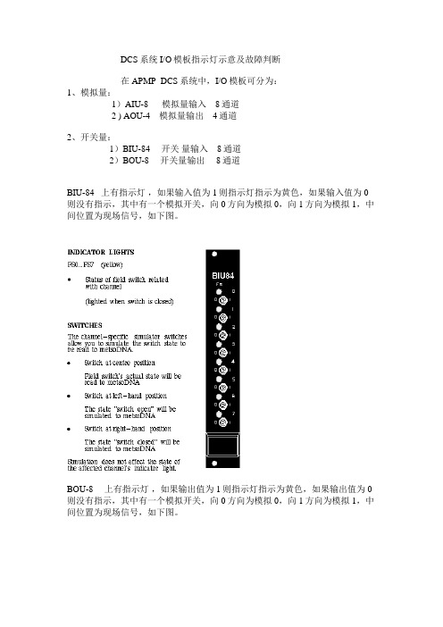
DCS系统I/O模板指示灯示意及故障判断在APMP DCS系统中,I/O模板可分为:1、模拟量:1)AIU-8 模拟量输入 8通道2 ) AOU-4 模拟量输出 4通道2、开关量:1)BIU-84 开关量输入 8通道2)BOU-8 开关量输出 8通道BIU-84 上有指示灯,如果输入值为1则指示灯指示为黄色,如果输入值为0则没有指示,其中有一个模拟开关,向0方向为模拟0,向1方向为模拟1,中间位置为现场信号,如下图。
BOU-8 上有指示灯,如果输出值为1则指示灯指示为黄色,如果输出值为0则没有指示,其中有一个模拟开关,向0方向为模拟0,向1方向为模拟1,中间位置为现场信号,如下图。
AIU-8 模拟量输入 8通道AOU-4 模拟量输出 4通道LS 灯为红色表示外电路电阻小,LO 灯为红色表示外电路电阻大I+ 与I- 为电流测量点,可用万用表测量。
I- 与⊥为电压测量点,可用万用表测量。
二信号判断:电机信号分类:电机信号进APMPR控制分两部分:1)进21CC02或21CC03(即控制室)的信号为现场控制箱来的信号2)进21CC11、21CC12、21CC13 、14的信号为MCC房来的信号1、现场挂箱信号:1)L/R Local/Remote 就地/远程 BI2)JOG Local Start 就地点动 BI3) Fwd Jog Forward 就地正转 BI4)Rev Jog Reverse 就地反转 BI5)E-STOP Emergency stop 紧急停机 BI2、MCC 信号1)R Run feedback 运行反馈 BI2)MF MCC-Fault 无故障 BI3)RDY Ready to run 准备 BI4)CO Start 启动 BO5)CUR Actual current 电流反馈 AI6)CO1 Start 启动 BO7)CO2 Stop 停止 BO8)CR Reverse 反转 BO例:M241301电机为普通正反转电机,它的信号有现场挂箱信号1) L/R (Local/Remote)2) FWD (JOG FORWARD)3) REV (JOG REVERSE)4) CO (Start forward )5) CR ( reverse ) 反转6) R (Run feedback) 运行反馈7) MF其中:L/R 为 BIFWD 为 BIREV 为 BIR 为 BIMF 为BICO 为BOCR 为BO如果M24130要启动,1)必须先满足MF为1,也就是说,电气方面已准备好,如果MF灯没有指示,说明电气有故障;或模板线路有问题。
NI_USB_6009规格说明

NI USB-600914位, 48 kS/s低价位多功能数据采集卡•8路模拟输入通道(14位分辨率,48 kS/s)•2路模拟输出通道(12位分辨率, 150 S/s);12条数字I/O线,32分辨率计数器•方便而易于携带的总线供电型设计•获取用于OEM的仅含板卡的套件•可用于Windows、Mac OS X、Linux和Pocket PC的驱动软件•NI-DAQmx驱动软件和NI LabVIEW SignalExpress交互式数据记录软件概述NI USB-6009具有基本的数据采集功能,其应用范围包括简单的数据记录、便携式测量和学术机构的实验室试验。
该产品价位适于学生购买且其强大的功能足以用于更为复杂的测量应用。
Mac OS X和Linux 用户可下载NI-DAQmx Base驱动软件并使用LabVIEW或C为USB-6009编程。
NI开发了含有LabVIEW学生版副本的USB-6009学生套件,为仿真、测试和自动化的理论性课程补充了实践性实验。
上述套件仅供学生使用,是功能优、价格低、实践性强的学习工具。
若需更多信息,请访问NI教育产品网页:/academic/measurements.htm for more details。
要想取得更高的采样速度,更精确的测量质量,以及更多的测量通道,请参考高性能USB数据采集设备NI USB-6210和NI USB-6211。
每个NI USB数据采集设备均包含一份NI LabVIEW SignalExpress LE的副本,使您无需编程即可快速采集、分析并显示数据。
除了LabVIEW SignalExpress,USB数据采集模块还与下列NI应用软件版本(或更高版本)兼容——LabVIEW 7.x、LabWindows™/CVI 7.x、或Measurement Studio 7.x。
USB数据采集模块也与Visual Studio .NET、C/C++和Visual Basic 6兼容。
K-AIH01 8通道带HART模拟量输入模块使用说明书

HOLLiAS MACS -K系列模块2014年5月B 版HOLLiAS MAC-K系列手册- K-AIH01 8通道带HART模拟量输入模块重要信息危险图标:表示存在风险,可能会导致人身伤害或设备损坏件。
警告图标:表示存在风险,可能会导致安全隐患。
提示图标:表示操作建议,例如,如何设定你的工程或者如何使用特定的功能。
目录1.概述 (1)2.接口说明 (3)2.1模块单元示意图 (3)2.2IO-BUS (4)2.3模块的防混淆设计 (6)2.4模块地址跳线 (7)2.5现场接口电路原理 (8)3.指示灯说明 (12)4.其他特殊功能说明 (14)4.1抗220V AC功能 (14)4.2二线制外供电功能 (15)4.3诊断功能 (16)4.4冗余功能 (18)5.工程应用 (19)5.1底座选型说明 (19)5.2应注意事项 (20)6.尺寸图 (21)7.技术指标 (21)K-AIH018通道带HART模拟量输入模块1.概述K-AIH01为K系列8通道模拟量通道隔离输入模块,支持Profibus-DP协议、HART协议。
测量范围0~22.7mA模拟信号(默认出厂量程4~20mA),同时与现场HART智能执行器进行通信,以实现现场仪表设备的参数设置、诊断和维护等功能。
可以按1:1冗余配置使用。
无需跳线就可以设置为配电或不配电工作方式,可以接二线制仪表或四线制仪表。
K-AIH01模块具备强大的过流过压保护功能,误接±30VDC和过电流都不会损坏。
同时,配合增强型底座还可以做到现场误接220V AC不损坏。
K-AIH01模块支持带点热插拔、支持冗余配置,具备完善断线、短路、超量程诊断功能,面板设计有丰富的LED指示灯,除指示模块电源、故障、通讯信息外,每个通道也有指示灯,可以方便指示各通道的断线、短路、超量程等信息。
K-AIH01模块每个通道可设置不同的滤波参数以适应不同的干扰现场。
可以根据工艺需要,配合主控制器的不同运算周期,组成可快可慢的控制回路。
K-AI01 8通道模拟量输入模块使用说明书
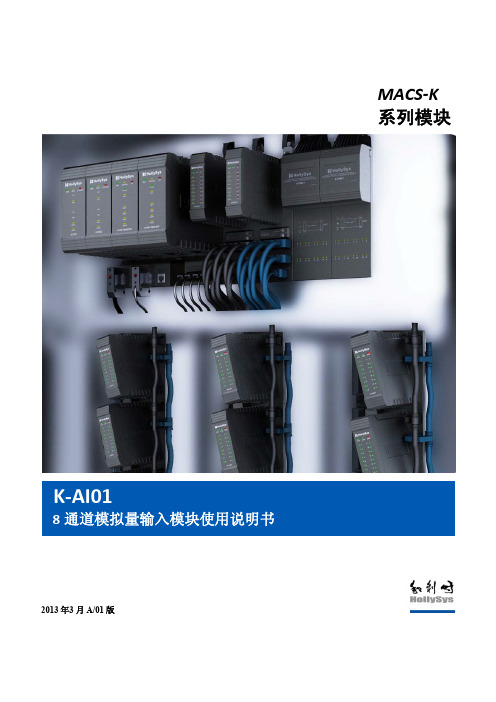
MACS‐K 系列模块
K‐AI01
8 通道模拟量输入模块使用说明书
通道 4 二线制外供电 24V+输出 NC 通道 5 电流输入正 通道 5 四线制电流输入负端 通道 5 二线制外供电 24V+输出 NC 通道 6 电流输入正 通道 6 四线制电流输入负端 通道 6 二线制外供电 24V+输出 NC 通道 7 电流输入正 通道 7 四线制电流输入负端 通道 7 二线制外供电 24V+输出 NC 8 通道电流输入正 通道 8 四线制电流输入负端 通道 8 二线制外供电 24V+输出 NC NC NC 测试端,现场电源+24V,禁止接线 测试端,现场电源地,禁止接线
第6页 共 20 页
通道 1
Байду номын сангаас
B1 C1 D1 A2
通道 2
B2 C2 D2 A3
通道 3
B3 C3 D3
通道 4
和利时公司版权所有
A4 B4
K-AI01
8 通道模拟量输入模块使用说明书
A/01
修订日期 2013-3-12
C4 D4 A5 通道 5 B5 C5 D5 A6 通道 6 B6 C6 D6 A7 通道 7 B7 C7 D7 A8 通道 8 B8 C8 D8 A 现场电源 B C D
图 1-3
模块单元安装位置图
2. 接口说明
2.1 模块单元示意图
K-AI01模块是否能正常通信、能正常处理数据,都跟模块接口有直接的关联。如图2-1所示为 K-AI01模块的外观接口示意图,图2-1中包括多功能总线电缆插头、现场信号接线端子、模块地址设 置开关和保险丝仓,下面将分别介绍各接口。
和利时公司版权所有
罗克韦尔自动化Micro800 4通道和8通道模拟电压 电流输入和输出模块安装说明书
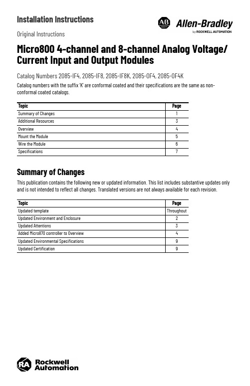
Installation InstructionsOriginal InstructionsMicro800 4-channel and 8-channel Analog Voltage/Current Input and Output ModulesCatalog Numbers 2085-IF4, 2085-IF8, 2085-IF8K, 2085-OF4, 2085-OF4KCatalog numbers with the suffix ‘K’ are conformal coated and their specifications are the same as non-conformal coated catalogs.Summary of ChangesThis publication contains the following new or updated information. This list includes substantive updates only and is not intended to reflect all changes. Translated versions are not always available for each revision.TopicPage Summary of Changes 1Additional Resources 3Overview 4Mount the Module 5Wire the Module 6Specifications7TopicPage Updated templateThroughoutUpdated Environment and Enclosure 2Updated Attentions3Added Micro870 controller to Overview 4Updated Environmental Specifications 9Updated Certification92Rockwell Automation Publication 2085-IN006E-EN-P - August 2022Micro800 4-channel and 8-channel Analog Voltage/Current Input and Output Modules Installation InstructionsEnvironment and EnclosurePrevent Electrostatic DischargeNorth American Hazardous Location ApprovalATTENTION: This equipment is intended for use in a Pollution Degree 2 industrial environment, in overvoltage Category II applications (as defined in EN/IEC 60664-1), at altitudes up to 2000 m (6562 ft) without derating.This equipment is not intended for use in residential environments and may not provide adequate protection to radio communication services in such environments.This equipment is supplied as open-type equipment for indoor use. It must be mounted within an enclosure that is suitably designed for those specific environmental conditions that will be present and appropriately designed to prevent personal injury resulting from accessibility to live parts. The enclosure must have suitable flame-retardant properties to prevent or minimize the spread of flame, complying with a flame spread rating of 5VA or be approved for the application if nonmetallic. The interior of the enclosure must be accessible only by the use of a tool. Subsequent sections of this publication may contain more information regarding specific enclosure type ratings that are required to comply with certain product safety certifications.In addition to this publication, see the following:•Industrial Automation Wiring and Grounding Guidelines, publication 1770-4.1, for more installation requirements.•NEMA Standard 250 and EN/IEC 60529, as applicable, for explanations of the degrees of protection provided by enclosures.ATTENTION: This equipment is sensitive to electrostatic discharge, which can causeinternal damage and affect normal operation. Follow these guidelines when you handle this equipment:•Touch a grounded object to discharge potential static.•Wear an approved grounding wriststrap.•Do not touch connectors or pins on component boards.•Do not touch circuit components inside the equipment.•Use a static-safe workstation, if available.•Store the equipment in appropriate static-safe packaging when not in use.The following information applies when operating this equipment in hazardous locations:Informations sur l’utilisation de cet équipement en environnements dangereux:Products marked “CL I, DIV 2, GP A, B, C, D” are suitable for use in Class I Division 2 Groups A, B, C, D, Hazardous Locations and nonhazardous locations only. Each product is supplied with markings on the rating nameplate indicating the hazardous location temperature code. When combining products within a system, the most adverse temperature code (lowest “T” number) may be used to help determine the overall temperature code of the system. Combinations of equipment in your system are subject to investigation by the local Authority Having Jurisdiction at the time of installation.Les produits marqués “CL I, DIV 2, GP A, B, C, D” ne conviennent qu'à une utilisation en environnements de Classe I Division 2 Groupes A, B, C, D dangereux et non dangereux. Chaque produit est livré avec des marquages sur sa plaque d'identification qui indiquent le code de température pour les environnements dangereux. Lorsque plusieurs produits sont combinés dans un système, le code de température le plus défavorable (code de température le plus faible) peut être utilisé pour déterminer le code de température global du système. Les combinaisons d'équipements dans le système sont sujettes à inspection par les autorités locales qualifiées au moment de l'installation.WARNING: EXPLOSION HAZARD•Do not disconnect equipment unless power has been removed or the area is known to be nonhazardous.•Do not disconnect connections to this equipment unless power has been removed or the area is known to be nonhazardous. Secure any external connections that mate to this equipment by using screws, sliding latches, threaded connectors, or other means provided with this product.•Substitution of components may impair suitability for Class I, Division 2.WARNING: RISQUE D’EXPLOSION •Couper le courant ou s'assurer quel'e nvironnement est classé non dangereux avant de débrancher l'équipement.•Couper le courant ou s'assurer quel'e nvironnement est classé non dangereux avant de débrancher les connecteurs. Fixer tous les connecteurs externes reliés à cet équipement à l'aide de vis, loquets coulissants, connecteurs filetés ou autres moyens fournis avec ce produit.•La substitution de composants peut rendre cet équipement inadapté à une utilisation en environnement de Classe I, Division 2.Rockwell Automation Publication 2085-IN006E-EN-P - August 20223Micro800 4-channel and 8-channel Analog Voltage/Current Input and Output Modules Installation InstructionsAdditional ResourcesYou can view or download publications at rok.auto/literature.ATTENTION:•This product is grounded through the DIN rail to chassis ground. Use zinc-plated chromate-passivated steel DIN rail to assure proper grounding. The use of other DIN rail materials (for example, aluminum or plastic) that can corrode, oxidize, or are poor conductors, can result in improper or intermittent grounding. Secure DIN rail to mounting surface approximately every 200 mm (7.8 in.) and use end-anchors appropriately. Be sure to ground the DIN rail properly. Refer to Industrial Automation Wiring and Grounding Guidelines, Rockwell Automation publication 1770-4.1, for more information.•To comply with UL restrictions, this equipment must be powered from a source compliant with the following: Class 2 or Limited Voltage/Current.•To comply with the CE Low Voltage Directive (LVD), all connected I/O must be powered from a source compliant with the following: Safety Extra Low Voltage (SELV) or Protected Extra Low Voltage (PELV).•Failure to connect a bus terminator module to the last expansion I/O module will result in a controller hard fault.•Do not wire more than 2 conductors on any terminal.WARNING:•When you connect or disconnect the Removable Terminal Block (RTB) with field side power applied, an electrical arc can occur. This could cause an explosion in hazardous location installations. Be sure that power is removed or the area is nonhazardous before proceeding.•If you connect or disconnect wiring while the field-side power is on, an electric arc can occur. This could cause an explosion in hazardous location installations. Be sure that power is removed or the area is nonhazardous before proceeding.•If you insert or remove the module while backplane power is on, an electric arc can occur. This could cause an explosion in hazardous location installations. The module does not support “Removal and Insertion Under Power” (RIUP) capability. Do not connect or disconnect the module while power is applied. Be sure power is removed before proceeding.•Do not unscrew the RTB hold down screws and remove the RTB while power is on. This could cause an explosion in hazardous location installations. Be sure that power is removed before proceeding.•Do not connect directly to line voltage. Line voltage must be supplied by a suitable, approved isolating transformer or power supply having short circuit capacity not exceeding 100 VA maximum or equivalent.•When used in a Class I, Division 2, hazardous location, this equipment must be mounted in a suitable enclosure with proper wiring method that complies with the governing electrical codes.ResourceDescriptionMicro830, Micro850, and Micro870 Programmable Controllers User Manual, publication 2080-UM002A more detailed description of how to install and use yourMicro830, Micro850, and Micro870 programmable controllers.Micro800 Bus Terminator Installation Instructions,publication 2085-IN002Information on installing the bus terminator module.Industrial Automation Wiring and Grounding Guidelines, publication 1770-4.1More information on proper wiring and grounding techniques.4Rockwell Automation Publication 2085-IN006E-EN-P - August 2022Micro800 4-channel and 8-channel Analog Voltage/Current Input and Output Modules Installation InstructionsOverviewThe Micro800™ expansion I/O is a modular I/O that complements and extends the capabilities of Micro850® and Micro870® controllers. These expansion I/O modules interface with the controllers using an I/O expansion port. I/O Module OverviewModule DescriptionDescription Description1Mounting screw hole / mounting foot 4Module interconnect latch 2Removable Terminal Block (RTB)5DIN rail mounting latch 3RTB hold down screws6I/O status indicatorThis equipment is sensitive to electrostatic discharge (ESD).Follow ESD prevention guidelines when handling this equipment.6Front viewRight top view2085-IF41Front view12085-OF4, 2085-OF4K16Front viewRight top view2085-IF8, 2085-IF8K5Rockwell Automation Publication 2085-IN006E-EN-P - August 20225Micro800 4-channel and 8-channel Analog Voltage/Current Input and Output Modules Installation InstructionsMount the ModuleFor more information on proper grounding guidelines, see the Industrial Automation Wiring and Grounding Guidelines, publication 1770-4.1.Module SpacingMaintain spacing from objects such as enclosure walls, wireways, and adjacent equipment. Allow 50.8 mm (2 in.) of space on all sides for adequate ventilation, as shown.Mounting Dimensions and DIN Rail MountingDIN Rail MountingThe module can be mounted using the following DIN rails: 35 x 7.5 x 1 mm (EN 50022 - 35 x 7.5).Before mounting the module on a DIN rail, use a flat-blade screwdriver in the DIN rail latch and pry it downwards until it is in the unlatched position.1.Hook the top of the DIN rail mounting area of the controller onto the DIN rail, and then press the bottom until the controller snaps onto the DIN rail.2.Push the DIN rail latch back into the latched position.Use DIN rail end anchors (Allen-Bradley® part number 1492-EA35 or 1492-EAHJ35) for vibration or shock environments.To remove your controller from the DIN rail, pry the DIN rail latch downwards until it is in the unlatched position.For environments with greater vibration and shock concerns, use the panel mounting method, instead of DIN rail mounting.Mounting dimensions do not include mounting feet or DIN rail latches.or 2085-IOF4K2085-IF8KMicro800 4-channel and 8-channel Analog Voltage/Current Input and Output Modules Installation InstructionsPanel MountingThe preferred mounting method is to use two M4 (#8) per module. Hole spacing tolerance: ±0.4 mm (0.016 in.). For mounting dimensions, see the Micro830®, Micro850, and Micro870 Programmable Controllers User Manual, publication 2080-UM002.Follow these steps to install your module using mounting screws.1.Place the module next to the controller against the panel where you are mounting it. Make sure that thecontroller and module are spaced properly.2.Mark drilling holes through the mounting screw holes and mounting feet then remove the module.3.Drill the holes at the markings, then replace the module and mount it.Leave the protective debris strip in place until you are finished wiring the module and any other devices. System AssemblyThe Micro800 expansion I/O module is attached to the controller or another I/O module by means of interconnecting latches and hooks, as well as the bus connector. The controller and expansion I/O modules must terminate with a 2085-ECR Bus Terminator module.Be sure to lock the module interconnect latches and tighten the RTB hold down screws before applying power to the module.For installation of the 2085-ECR module, see the Micro800 Bus Terminator Module Installation Instructions, publication 2085-IN002.Field Wiring ConnectionsIn solid-state control systems, grounding and wire routing helps limit the effects of noise due to electromagnetic interference (EMI).Wire the ModuleIncluded with your 2085-IF4, 2085-OF4, or 2085-OF4K module is a single 12-pin Removable Terminal Blocks (RTB). Included with your 2085-IF8 or 2085-IF8K module are two 12-pin RTB. Basic wiring of your module is shown below.Basic Wiring to the Module6Rockwell Automation Publication 2085-IN006E-EN-P - August 2022Rockwell Automation Publication 2085-IN006E-EN-P - August 20227Micro800 4-channel and 8-channel Analog Voltage/Current Input and Output Modules Installation InstructionsSpecificationsGeneral SpecificationsAttribute 2085-IF42085-OF4, 2085-OF4K2085-IF8, 2085-IF8K Number of I/O 48Dimensions HxWxD28 x 90 x 87 mm (1.1 x 3.54 x 3.42 in.)44.5 x 90 x 87 mm (1.75 x 3.54 x 3.42 in.)Shipping weight, approx.140 g (4.93 oz)200 g (7.05 oz)270 g (9.52 oz)Bus current draw, max5V DC, 100 mA 24V DC, 50 mA5V DC, 160 mA 24V DC, 120 mA5V DC, 110 mA 24V DC, 50 mAWire sizeWiring category (1)(1)Use this Conductor Category information for planning conductor routing. See Industrial Automation Wiring and Grounding Guidelines, publication 1770-4.1.2 – on signal ports Wire typeShieldedTerminal screw torque 0.5…0.6 N•m (4.4…5.3 lb•in)(2)(2)RTB hold down screws should be tightened by hand. They should not be tightened using a power tool.Power dissipation, total 1.7 W3.7 W1.75 WEnclosure type rating None (open-style)Status indicators 1 green health indicator 4 red error indicator1 green health indicator1 green health indicator 8 red error indicatorsIsolation voltage 50V (continuous), Reinforced Insulation Type, channel to system.Type tested @ 720V DC for 60 s North American temp code T4AT5Input SpecificationsAttribute 2085-IF42085-IF8, 2085-IF8K Number of inputs 48Resolution Voltage Current 14 bits (13 bits plus sign bit)1.28 mV/cnt unipolar; 1.28 mV/cnt bipolar 1.28 µA/cntData format Left justified, 16 bit 2 s complement Conversion type SARUpdate rate <2 ms per enabled channel without 50 Hz/60 Hz rejection, <8 ms for all channel 8 ms with 50 Hz/60 Hz rejectionStep response time up to 63%4...60 ms without 50Hz/60 Hz rejection – depends on number of enabled channel and filter setting 600 ms with 50 Hz/60 Hz rejection Input current terminal, user configurable 4...20 mA (default)0...20 mA Input voltage terminal,user configurable ±10V 0 (10V)Input impedance Voltage terminal >1 M ΩCurrent terminal <100 ΩAbsolute accuracy ±0.10% Full Scale @ 25 °CAccuracy drift with tempVoltage terminal – 0.00428 % Full Scale/ °C Current terminal – 0.00407 % Full Scale/ °CMinMaxSolid 0.34 mm 2 (22 AWG) 2.5 mm 2 (14 AWG)Copper wire rated @ 90°C (194°F), or greater, 1.2mm (3/64 in.) insulation maxStranded0.20 mm 2 (22 AWG)2.5 mm 2 (14 AWG)Micro800 4-channel and 8-channel Analog Voltage/Current Input and Output Modules Installation InstructionsCalibration required Factory calibrated. No customer calibration supported.Overload, max30V continuous or 32 mA continuous, one channel at a time.Channel diagnostics Over and under range or open circuit condition by bit reportingOutput SpecificationsAttribute2085-OF4, 2085-OF4KNumber of outputs4Resolution Voltage Current 12 bits unipolar; 11 bits plus sign bipolar 2.56 mV/cnt unipolar; 5.13 mV/cnt bipolar 5.13 µA/cntData format Left justified, 16-bit 2 s complement Step response time up to 63% 2 msConversion rate, max 2 ms per channelOutput current terminal, user configurable 0 mA output until module is configured 4…20 mA (default)0…20 mAOutput voltage terminal, user configurable ±10V 0 (10V)Current load on voltage output,max 3 mAAbsolute accuracy Voltage terminal Current terminal 0.133% Full Scale @ 25 °C or better 0.425 % Full Scale @ 25 °C or betterAccuracy drift with temp Voltage terminal – 0.0045% Full Scale/ °CCurrent terminal – 0.0069% Full Scale/ °C Resistive load on mA output15…500 Ω @ 24V DC Environmental SpecificationsAttribute ValueTemperature, operating IEC 60068-2-1 (Test Ad, Operating Cold),IEC 60068-2-2 (Test Bd, Operating Dry Heat),IEC 60068-2-14 (Test Nb, Operating Thermal Shock): -20…+65 °C (-4…+149 °F)Temperature, surrounding air, max65 °C (149 °F)Temperature, nonoperating IEC 60068-2-1 (Test Ab, Unpackaged Nonoperating Cold),IEC 60068-2-2 (Test Bb, Unpackaged Nonoperating Dry Heat),IEC 60068-2-14 (Test Na, Unpackaged Nonoperating Thermal Shock): -40…+85 °C (-40…+185 °F)Relative humidity IEC 60068-2-30 (Test Db, Unpackaged Damp Heat):5…95% noncondensingVibration IEC 60068-2-6 (Test Fc, Operating):2 g @ 10…500 HzShock, operating IEC 60068-2-27 (Test Ea, Unpackaged Shock):25 gShock, nonoperating IEC 60068-2-27 (Test Ea, Unpackaged Shock): 25 g – for DIN rail mount35 g – for panel mountEmissions IEC 61000-6-4ESD immunity IEC 61000-4-2:6 kV contact discharges 8 kV air dischargesInput Specifications (Continued)Attribute2085-IF42085-IF8, 2085-IF8K8Rockwell Automation Publication 2085-IN006E-EN-P - August 2022Rockwell Automation Publication 2085-IN006E-EN-P - August 20229Micro800 4-channel and 8-channel Analog Voltage/Current Input and Output Modules Installation InstructionsRadiated RF immunity IEC 61000-4-3:10V/m with 1 kHz sine-wave 80% AM from 80…6000 MHz EFT/B immunity IEC 61000-4-4:±2 kV @ 5 kHz on signal ports ±2 kV @ 100 kHz on signal portsSurge transient immunity IEC 61000-4-5:±1 kV line-line(DM) and ±2 kV line-earth(CM) on signal ports Conducted RF immunityIEC 61000-4-6:10V rms with 1 kHz sine-wave 80% AM from 150 kHz…80 MHzCertificationsCertification (when product is marked)(1)(1)See the Product Certification link at rok.auto/certifications for Declaration of Conformity, Certificates, and other certification details.Valuec-UL-usUL Listed Industrial Control Equipment, certified for US and Canada. See UL File E322657.UL Listed for Class I, Division 2 Group A,B,C,D Hazardous Locations, certified for U.S. and Canada. See UL File E334470CEEuropean Union 2014/30/EU EMC Directive, compliant with:EN 61326-1; Meas./Control/Lab., Industrial Requirements EN 61000-6-2; Industrial Immunity EN 61000-6-4; Industrial EmissionsEN 61131-2; Programmable Controllers (Clause 8, Zone A & B)European Union 2011/65/EU RoHS, compliant with:EN IEC 63000; Technical documentation RCM Australian Radiocommunications Act, compliant with:EN 61000-6-4; Industrial EmissionsKC Korean Registration of Broadcasting and Communications Equipment, compliant with:Article 58-2 of Radio Waves Act, Clause 3EAC Russian Customs Union TR CU 020/2011 EMC Technical Regulation Russian Customs Union TR CU 004/2011 LV Technical Regulation Morocco Arrêté ministériel n° 6404-15 du 29 ramadan 1436UKCA 2016 No. 1091 – Electromagnetic Compatibility Regulations 2016 No. 1101 – Electrical Equipment (Safety) Regulations2012 No. 3032 – Restriction of the Use of Certain Hazardous Substances in Electrical and Electronic Equipment RegulationsEnvironmental Specifications (Continued)AttributeValueMicro800 4-channel and 8-channel Analog Voltage/Current Input and Output Modules Installation Instructions Notes:10Rockwell Automation Publication 2085-IN006E-EN-P - August 2022Micro800 4-channel and 8-channel Analog Voltage/Current Input and Output Modules Installation Instructions Notes:Rockwell Automation Publication 2085-IN006E-EN-P - August 202211Publication 2085-IN006E-EN-P - August 2022 | Supersedes Publication 2085-IN006D-EN-P - December 2019Copyright © 2022 Rockwell Automation, Inc. All rights reserved. Printed in Singapore.Rockwell Otomasyon Ticaret A.Ş. Kar Plaza İş Merkezi E Blok Kat:6 34752, İçerenköy, İstanbul, Tel: +90 (216) 5698400 EEE Yönetmeli ğine UygundurPN-658773Allen-Bradley, expanding human possibility, FactoryTalk, Micro800, Micro830, Micro850, Micro870, Rockwell Automation, and TechConnect are trademarks of Rockwell Automation,Inc.Trademarks not belonging to Rockwell Automation are property of their respective companies.Connect with us.Waste Electrical and Electronic Equipment (WEEE)Rockwell Automation maintains current product environmental compliance information on its website at rok.auto/pec .At the end of life, this equipment should be collected separately from any unsorted municipal waste.Rockwell Automation SupportUse these resources to access support information.Documentation FeedbackYour comments help us serve your documentation needs better. If you have any suggestions on how to improve our content, complete the form at rok.auto/docfeedback .Technical Support CenterFind help with how-to videos, FAQs, chat, user forums, and product notification updates.rok.auto/support KnowledgebaseAccess Knowledgebase articles.rok.auto/knowledgebase Local Technical Support Phone NumbersLocate the telephone number for your country.rok.auto/phonesupport Literature LibraryFind installation instructions, manuals, brochures, and technical data publications.rok.auto/literature Product Compatibility and Download Center (PCDC)Download firmware, associated files (such as AOP, EDS, and DTM), and access product release notes.rok.auto/pcdc。
AD0809中文资料

ADC0809中文资料ADC0809是带有8位A/D转换器、8路多路开关以及微处理机兼容的控制逻辑的CMOS组件。
它是逐次逼近式A/D转换器,可以和单片机直接接口。
(1)ADC0809的内部逻辑结构由下图可知,ADC0809由一个8路模拟开关、一个地址锁存与译码器、一个A/D转换器和一个三态输出锁存器组成。
多路开关可选通8个模拟通道,允许8路模拟量分时输入,共用A/D转换器进行转换。
三态输出锁器用于锁存A/D转换完的数字量,当OE端为高电平时,才可以从三态输出锁存器取走转换完的数据。
(2).ADC0809引脚结构ADC0809各脚功能如下:D7-D0:8位数字量输出引脚。
IN0-IN7:8位模拟量输入引脚。
VCC:+5V工作电压。
GND:地。
REF(+):参考电压正端。
REF(-):参考电压负端。
START:A/D转换启动信号输入端。
ALE:地址锁存允许信号输入端。
(以上两种信号用于启动A/D转换).EOC:转换结束信号输出引脚,开始转换时为低电平,当转换结束时为高电平。
OE:输出允许控制端,用以打开三态数据输出锁存器。
CLK:时钟信号输入端(一般为500KHz)。
A、B、C:地址输入线。
ADC0809对输入模拟量要求:信号单极性,电压范围是0-5V,若信号太小,必须进行放大;输入的模拟量在转换过程中应该保持不变,如若模拟量变化太快,则需在输入前增加采样保持电路。
地址输入和控制线:4条ALE为地址锁存允许输入线,高电平有效。
当ALE线为高电平时,地址锁存与译码器将A,B,C三条地址线的地址信号进行锁存,经译码后被选中的通道的模拟量进转换器进行转换。
A,B和C为地址输入线,用于选通IN0-IN7上的一路模拟量输入。
通道选择表如下表所示。
C B A 选择的通道0 0 0 IN00 0 1 IN10 1 0 IN20 1 1 IN31 0 0 IN41 0 1 IN51 1 0 IN61 1 1 IN7数字量输出及控制线:11条ST为转换启动信号。
- 1、下载文档前请自行甄别文档内容的完整性,平台不提供额外的编辑、内容补充、找答案等附加服务。
- 2、"仅部分预览"的文档,不可在线预览部分如存在完整性等问题,可反馈申请退款(可完整预览的文档不适用该条件!)。
- 3、如文档侵犯您的权益,请联系客服反馈,我们会尽快为您处理(人工客服工作时间:9:00-18:30)。
三、双向晶闸管输出接口
双向晶闸管具有双向导通功能,能在交流、 大电流场合使用,且开关无触点,因此在工业控 制领域有着极为广泛的应用。双向晶闸管隔离驱 动电路的设计是光耦合双向晶闸管驱动器。与一 般的光耦不同,在于其输出部分是一硅光敏双向 晶闸管,有的还带有过零触发检测器,以保证在 电压接近为零时触发晶闸管。
固态继电器由光电耦合电路、触发电路、开关电路、过零 控制电路和吸收电路五部分构成。这五部分被封装在一个 六面体外壳内,外面有四个引脚。非过零型SSR没有过零 控制电路。
A
C 负载
输入
受 触发 开关 吸收 光 控制 电路 电路
电源
B
耦合电路
过零控制
D
1、直流型固态继电器
直流型固态继电器主要用于直流大功率控制 场合。其输入端为一光电耦合电路,因此可用 OC门或晶体管直接驱动,驱动电流一般3~ 30mA,输入电压为5~30V,其输出端为晶 体管输出,输出电压30~180V。
二、DAC0832与80C51单片机的接口
1、单缓冲工作方式
适用只有一路模拟量输出,或有几路模拟量输出但并不要求 同步的系统。
P2.7
80C51
P0 WR VSS
DAC0832
+5V
CS
VCC
ILE
XFER
Rfb
D0
IOUT1
-
VO
D7
IOUT2
+
WR1
WR2 DGND
VREF
-5V
AGND
例:锯齿波产生电路:
INC DPTR
;修改通道号
MOVX @DPTR,A ;再次启动A/D转换
DJNZ R2,NEXT CLR EX1
;关中断
RETI
;中断返回
END
8.3 开关量接口
开关量的输入与输出,CPU通过对输入信息分析是 “1”还是“0”,即可知开关是合上还是断开。如果控 制某个执行器的工作状态,只需送出“0”或“1”,即 可由操作机构执行。但是由于工业现场存在着电、磁、 振动、温度等各种干扰及各类执行器所要求的开关电 压量级及功率不同,所以在接口电路中需要选用不同 的元器件,还需要采用各种缓冲、隔离与驱动措施。
R
R
R
R
R
R
I7 I6 I5 I4 I3 I2 I1 I0 2R 2R 2R 2R 2R 2R 2R 2R 2R
0 1 0 1 0 1 0 1 0 1 0 1 0 1 0 1 Rfb
IOUT1 IOUT2
+
VO
D7 D6 D5 D4 D3 D2 D1 D0
8.1.1 D/A转换器的原理
输出电压的大小与数字量具有对应的关系。
1G
2G
4 8 A 1 2
5.1KΩ×8
接口程序如下:
BCD: CLR P1.0 MOVX A,@R0 ANL A,#0FH MOV 20H,A MOVX A,@R0 ANL A,#0F0H SWAP A MOV 21H,A
RET
;准备选通和读入2位BCD码 ;产生读信号 ;取个位数 ;存入片内RAM 的20H单元 ;重读2位BCD码 ;取十位数 ;调整到低半字节 ;存入片内RAM的21H单元
DAC0832是8位D/A转换器,片内有输入数 据寄存器,可直接与单片机接口。DAC0832以电 流形式输出,当需要转换为电压输出时,可外接 运算放大器。
一、DAC0832内部结构及引脚
DI7~DI0
ILE CS WR1
输入 锁存器
LE1 &
DAC
寄存器
LE2 &
D/A 转换器
&
LE=1输出跟随输入 IE=0锁存
8.2.2 ADC0809芯片及其与单片机的接口
一、ADC0809的内部结构
START
CLK
IN7
IN0
C B A
ALE
8路
三
模拟
8位
态
开关
A/D
输
转换
出
3
器
锁 存
地址锁
器
存与
译码
VREF(+)
VREF(-)
EOC
D7 D6 D5 D4 D3 D2 D1 D0
OE VCC GND
8.2.2 ADC0809芯片及其与单片机的接口
;P0.7为高电平,转ELSE
LJMP KF8 ;P0.7为低电平,执行KF8程序
ELSE:… …
二、拨盘开关与单片机的接口
+5V
A
A
8421 8421
P0.0
80C51
P0.7 P1.0
≥1
RD
74LS244
1Y1 1A1 1Y2 1A2 1Y3 1A3 1Y4 1A4 2Y1 2A1 2Y2 2A2 2Y3 2A3 2Y4 2A4
引脚:
IN0~IN7:8路模拟量; C、B、A:8路模拟开关的地址信号; ALE:地址锁存信号; START:启动A/D控制信号。上升沿复位内部逐次逼近寄 存器,下降沿开始A/D转换; EOC:转换结束信号; OE:输出允许。OE为高电平时,转换结果数据出现在 D7~D0引脚。当OE为低电平时,呈高阻状态。
8.3.1 开关量输入接口
一、独立键盘与单片机的接口
+5V
P0.0
80C51
P0.7 P1.0
≥1
RD
74LS244
1Y1 1A1 1Y2 1A2 1Y3 1A3 1Y4 1A4 2Y1 2A1 2Y2 2A2 2Y3 2A3 2Y4 2A4
1G
2G
读扳键开关状态程序段:
CLR P1.0
;准备选通和读入开关状态
I VREF / R
I7 I / 21 , I6 I / 22......I10 I / 28
IOUT
I 2
d
7
I 4
d6
......
I 256
d0
VO
-R fb IOUT1
VREF 28
(d7 27
d6 26
...... d0 20 )
8.1.2 DAC0832芯片及其与单片机接口
;中断服务程序入口
;置数据区首地址 ; 转换通道数 ;为边沿触发方式 ;开中断 ;允许中断 ;指向IN0通道 ;启动A/D转换 ;等待中断
PINT1 NEXT:
ORG 2100H
;中断服务程序入口
MOVX A,@DPTR ;读取转换后数据
MOV @R1,A ;数据存入RAM中
INC R1
;修改数据区指针
VIN
-
比较器
+
计
数
器
时钟 控制逻辑
T2’
t
T1
T2
T2 =
T1 VREF
VIN
N D= VREF VIN
8.2.2 ADC0809芯片及其与单片机的接口
主要性能为: 分辨率为8位; 单+5V供电,模拟输入电压范围为0~+5V; 8路模拟输入; 可锁存三态输出,输出与TTL电平兼容; 时钟频率范围:典型值为时钟频率640KHz,转换时间约为 100μS。
MOV DPTR,#0DFFFH ;0832(1)输入锁存器地址
MOV A,#data1
MOVX @DPTR,A ;data1送入0832(1)输入锁存器
MOV DPTR,#0BFFFH ;0832(2)输入锁存器地址
MOV A,#data2
MOVX @DPTR,A ;data2送入0832(2)输入锁存器
MOV DPTR,#7FF8H
;指向0通道
MOV R7,#08H
;置通道数
LOOP: MOVX @DPTR,A
;启动A/D转换
JNB P3.3,$
JB P3.3,$
;查询A/D转换结束
MOVX A,@DPTR
;读取A/D转换结果
MOV @R1,A
;存储数据
INC DPTR
;指向下一个通道
INC R1
8.3.2 开关量输出接口
一、输出接口的隔离
VC
J
光耦合器是以光为媒介传输信号的器件,它把一个发光二极 管和一个光敏三极管封装在一个管壳内,发光二极管加上正 向输入电压信号(>1.1V)就会发光,光信号作用在光敏三 极管基极产生基极光电流使三极管导通,输出电信号。
二、继电器输出接口
继电器输出,可完成从低压直流到高压交流的过 渡。在经光耦合器光电隔离后,直流部分给继电 器控制线圈供电,而其输出触点则可直接于 220V相接。
第8章 模拟通道接口
8.1 D/A转换器及其与单片机接口 8.2 A/D转换器及其与单片机接口 8.3开关量接口
8.1 D/A转换器及其与单片机接口
8.1.1 D/A转换器的原理 一、D/A转换器的基本原理 T型电阻网络D/A转换器 :
I I7 I6 I5 I4 I3 I2 I1 I0
VREF
R
2R
- A2 +
VOUT
+5V
VOUT
-5V
例:小功率直流电机驱动:
PWM直流电机调速:
5V
正向快速 0V
5V
正向慢速 0V 反向快速 0V
-5V
反向慢速 0V
-5V
电机正传控制程序: MOV DPTR,#7FFFH
DAMOT: MOV A,#80H MOVX @DPTR,A ;输出电平0V ACALL DELAY1 ;维持输出0V电平 MOV A,0FFH MOVX @DPTR,A ;输出电平+5V ACALL DELAY2 ;维持输出电平+5V SJMP DAMOT
四、固态继电器输出接口