丰田-S_86 (Chassis)
丰田八十年代经典跑车AE86和4A-GE的历史

AE86和4A-GE的历史从4A-GE开始来慢慢介绍AE86是再好不过了。
4A-GE是旧丰田跑车的主要心脏,从心脏下手,完全融会贯通之后,要改装引擎你就会有一个很清楚的蓝图,引擎从哪些车可以拿下?哪些引擎可以放在原厂变速箱,开始吧!现在的‘A’ 系列引擎已经跟第一代的A系列引擎大大不同了。
丰田在1934年9月制造出第一个A系列引擎,当时是一个六缸3.4公升引擎,直到今天的A系列引擎仍然是在市场上成功的多功能四缸引擎。
A系列可以说是丰田在八十年代中一个精简,轻巧,有力而且高功效的引擎。
八十年代的4A-GE也成为丰田在后来的第二代4A-GE上改良的基础。
当年第一代高功效引擎有下列几样,3M, 5M-GE, 6M-GE series; the 9R, 8R-G (10R), 18R-G, 18R-GE, 和2T-G, 2T-GE and 3T-GE 系列在1982年,丰田推出1G-GE双轮轴引擎(DOHC),也创造了第二代的4气门高性能引擎,丰田也将这颗引擎正式的用在赛车上面。
这时DOHC引擎也开始成为了市场的主流,开始了TWIN CAM引擎的大竞争。
在1982年丰田推出了TURBO的3T-TGE和1985推出的双TURBO 的1G-GTE,在1988年日本版的SUPRA上面有用了TURBO的7M-GTE引擎。
在1985年日本丰田也推出了第一代的机械增压(supercharged)的1G-GZE引擎,再过一年之后随之推出4A-GZE引擎,这颗引擎当年放在第一代的MR2上面.在第二代丰田引擎也考虑到了市场上的热衷的追随者,对第二代引擎有了以下的调教。
丰田对新一代的引擎有了不同的目标,低污染,低耗油,精简,轻巧,低噪音,反应佳,这些原因明确了指出丰田对未来的引擎有了一个清楚的方向.1982年丰田开始研究第二代4气门双凸轮引擎,1G-GE(后来Celica的引擎)和4A-GE (AE86. 92. 101 .111. 第一代MR2用的引擎),这两个引擎也完全往高性能的需求而推出。
丰田车型代码

丰田车型代码-参考丰田:ZZE 花冠ZRE卡罗拉GRJ霸道4000TRJ霸道2700GRS188L皇冠2.5GRS182L皇冠3.0GRX188L锐志ACA RAV4ACR 大霸王ACV 佳美RZB考斯特ACV并不代表任何意思,它是一组,AVC40或者ACV41 代表的意思就是配置为2.0或者2.4的发动机ACV40代表2.4的2AZ发动机ACV41代表2.0,1AZ的发动机.回答人的补充2009-04-26 13:26拿一个凯美瑞的车型代码做实例:ACV40L-JEAGKCACV40 L J E A G K C1 2 3 4 5 6 7 81、基本型号代码:配置2AZ-FE的2.4L发动机2、方向盘位置:左侧驾驶3、制造型号:旗舰型4、车身类型:4门5、变速箱类型:配置5速自动变速箱6、级别:LUX7、发动机规格:丰田车型的代码1更新日期: 2010-4-11 23:53:36 ZZE122花冠1.8ZRE120花冠1.6ZRE15#卡罗拉GRJ120霸道4000RZJ120、TRJ120霸道2700VZJ95霸道3400RZJ95旧霸道2700ACA21、ACA33RAV4TCR10.20、ACR30、ACR50大霸王JZS133、JZS155、GRS182、GRS188、GRS20#皇冠GRX122、GRX121锐志NHW20普锐斯ACV30佳美2.4ACV31佳美2.0MCV10、VCV10、MCV20佳美3.0SXV10、SXV20佳美2.2AXP41、AXP42、SCP4#、NCP9#威驰ACV4#凯美瑞RN8#、YN8#、RZN14#的士头RZB4#、RZB5#、HZB5#、BB4#、BB5#中巴FZJ80、FZJ100陆地巡洋舰4500UZJ100、UZJ200 陆地巡洋舰4700YR21LG小霸王RZH10#、RZH104、RZH105、THR22#海狮UCF10、UCF20凌志400UCF30凌志430JZS147、JZS160、GRS19#、凌志GS300MCU3#凌志RX300ZZE 花冠ZRE卡罗拉GRJ霸道4000TRJ霸道2700GRS188L皇冠2.5GRS182L皇冠3.0GRX188L 锐志ACA RAV4ACR 大霸王ACV 佳美RZB考斯特VIN是英文Vehicle Identification Number(车辆识别码)的缩写。
丰田车系统保险丝继电器中英文名称对照精心整理含考核

丰田车系统保险丝中英文名称英文缩略语名称相关的系统1 FUSE 保险丝--- 熔断丝2 DOME 保险丝---室内灯系统3 STOP 保险丝--- 停车灯系统4 HORN 保险丝--- 喇叭5 ST 保险丝--- 起动机6 DEFOG 保险丝--- 除雾器系统7 TRUN 保险丝--- 转向信号灯系统8 PANEL 保险丝--- 仪表板9 GAUGE 保险丝--- 组合仪表10 ENGINE 保险丝--- 发动机11 RADIO 保险丝--- 音响系统12 CHARGE 保险丝--- 充电系统13 IGN 保险丝--- 点火系统14 FOG 保险丝--- 防雾灯系统15 WIPER 保险丝--- 刮水器和洗涤器系统16 CIG 保险丝--- 点烟器17 TAIL 保险丝--- 尾灯18 A/C 保险丝--- 空调系统19 EFI 保险丝--- 电子控制燃油喷射系20 AIR SUS 保险丝--- 空气悬架系统21 ABS 保险丝---- 防抱死制动系统22 SRS 保险丝---- 辅助乘员保护系统23 ECU 保险丝---- 电子控制单元24 HAZ-HORN 保险丝-----危险-喇叭25 POWER 保险丝--- 电动车窗控制系统26 CB DOOR 保险丝--- 电动门锁控制系统27 FL RAD FAN 保险丝--- 散热器风扇28 HTR 保险丝--- 加热器系统29 HEAD RH-LWR 保险丝--- 右前照灯近光30 HEAD LH-LWR 保险丝--- 左前照灯近光31 HEAD RH-UPR 保险丝--- 右前照灯远光32 HEAD LH-UPR 保险丝--- 左前照灯远光33 TEMP ---温度34 O/D ---超速35 A/T ---自动变速器36 TDCL ---故障诊断连接器37 TEL ---车载电话38 RR A/C ---保险丝后空调系统39 RR SEAT-HTR 保险丝--- 后座加热器系统40 SEAT-HTR 保险丝--- 前座加热器系统41 ECU-IG 保险丝巡航控制系统、电动倾斜和伸缩控制系统、ABS 系统42 ECU-B 保险丝安全气囊警告灯43 DOME-CLOCK 保险丝 ---车内照明系统、液晶车内后视镜、电子表AIR CON [A,C] 空调BACK 倒车灯CIG [CIGAR] 点烟器LIG。
Rane CM 86 操作 维修手册说明书

OPERATING / SERVICE MANUAL CM 86QUICK STARTThink of this like a fortune cookie: you have to read the saying before you eat it. But unlike a fortune cookie we don’t want you to break your CM 86 before getting the message. So here’s your fortune:Rane adheres to the AES/ANSI/IEC standards of pin 2 positive, pin 3 negative and pin 1 ground. Choose between either the 3-pin (XLR-type) or the terminal strip MIC IN. Use only ONE; they are in parallel and do NOT sum. The LINE IN (unbalanced 1/4") is grounded when not used. This allows the MIC/LINE switch to act as an input MUTE switch when-ever the LINE IN jack is not used. Likewise, if it is used then the MIC/LINE switch acts like a true source selector.Set the rear-mounted MIC GAIN control as necessary for your mic. Use the OL indicator as an adjustment aid: increase gain until this LED occasionally lights. Optimum noise performance results from taking as much gain as possible. (The OL indi-cator on the front panel parallels the one on the rear.) Select PHANTOM POWER as needed for each channel indepen-dently. When setting channel equalization, use the IN/OUT switch to compare equalized with unequalized material.When using the AUX A/B level controls, remember to set the desired take-off location using the PRE/POST switches. PRE takes this signal before the Channel LEVEL controls, allowing independent operation of both. POST takes this signal after the Channel LEVEL controls, allowing the LEVEL controls to turn the Aux levels up/down simultaneously. Set the OUTPUT SELECT to assign each input channel to the desired output. Choose between “A” only, “B” only or “AB” both. Note that choosing only one, say “A,”routes this input to both MASTER 1A and MASTER 2A outputs, but nothing goes to either B output.When setting input AUX A/B and LEVEL A/B controls, keep an eye on the appropriate PRE-OUTPUT OVERLOAD in-dicators. They monitor overloading of the critical summing stages. Use the METER & HEADPHONE ASSIGN switch to select the desired output for metering and monitoring. The HEADPHONE connects to the same point as the OUTPUT ME-TERS — what you see is what you hear.Read the Rane FLEX USERS GUIDE for details about the Flex DIN connectors. Expansion and augmentation of the CM 86 is easily done using this handy bus. TAPE OUT is taken after the MASTER INSERT LOOPS and before the MASTER 1 & 2 OUT LEVEL controls. The MASTER INSERT LOOPS do not affect the AUX A & B outputs. All four MASTER OUTS are driven by high-current cross-coupled line drivers which will drive lines 1000 feet (305 meters) using Belden 8451 or equal wire.Miscellaneous: The CM 86 does NOT invert signals. Use the LIFT (ground lift) switch to help eliminate stubborn hum problems. NEVER CONNECT ANYTHING EXCEPT AN APPROVED RANE RS 2 (the big one) POWER SUPPLY TO THE RED JACK ON THE REAR OF THE UNIT.Good fortune and great wealth are coming your way.SYSTEM CONNECTIONWhen first connecting the CM 86, LEAVE THE POWER SUPPLY FOR LAST. This gives you a chance to make mis-takes and correct them without damaging your fragile speakers, ears and nerves.INPUTS. Each input channel has two MIC IN connectors. The 3-pin (XLR-type) connector and the terminal strip are wired in parallel and either one works equally well; however, they do NOT sum. USE ONLY ONE. Choose strictly from a re-quired hardware point-of-view, there is no performance trade-off. Wiring convention conforms to the AES/ANSI/IEC stan-dard of pin 2 positive, pin 3 negative and pin 1 ground, with the shell being tied to chassis. Microphones requiring Phantom Powering must tie pin 1 to the shield, otherwise the Phantom Power circuit is not completed. The LINE IN is an unbalanced 1/4" jack, and may be used in conjunction with the MIC IN. The MIC/LINE switch then operates as a selector switch. When(continues on last page...)FRONT PANEL DESCRIPTION1. INPUT SOURCE SELECTOR. This slide switch selects between MIC or LINE inputs. Both inputs may be used; in which case this switch acts as a true source selector. If the LINE input is not used then it is internally grounded and this switch acts like a Mic Mute when moved to the LINE position.2. INPUT OVERLOAD INDICATOR. This red LED parallels an identical one in the rear and monitors all critical input nodes. It lights whenever these levels exceed 4dB below clipping. Occasional flickering is normal; however., it should not be allowed to light steadily.3. INPUT EQUALIZATION CONTROLS. A two-band shelving LOW (bass) and HIGH (treble) tone control circuit. These controls adjust the frequency contour of both MIC and LINE inputs. The EQ is located before the INSERT LOOP.4. EQ IN/OUT ENGAGE SWITCH. This slide switch controls the EQ circuits. Useful for comparing equalized (IN) with unequalized (OUT) signals, or for guaranteeing flat frequency response (OUT).5. PRE/POST AUX-ASSIGN SWITCHES. These slide switches allow choosing the AUX take-off points. Selecting PRE places the AUX Level before the Channel LEVEL controls, thus allowing independent operation between the two. Selecting POST takes the AUX Level after the Channel LEVEL controls, thereby allowing the LEVEL controls to affect all outputs.6. AUX CONTROLS. Separate controls for mixing the input channel into the AUX A and AUX B Output (Send) signals.7. OUTPUT SELECT SWITCH. A three-position slide switch that selects routing of this input channel. Choosing either “A” or “B” puts all of this signal into only the A or B outputs. Choosing “AB” puts this signal equally into both.8. CHANNEL LEVEL A/B CONTROLS (Input Faders). Concentric controls used to set the amount of signal mixed into the MASTER A and B outputs.9. TAPE/CD MIX CONTROLS. Three rotary controls that set the amount of the Tape, Tuner, or CD input signals mixed in with the AUX A, AUX B or MASTER outputs.IO. AUX IN/RETURN LEVEL CONTROL. Concentric knobs that control the amount of AUX signal coming into the AUX OUT/IN jacks (on the ring). Often the return path from an effects box in the AUX OUT/IN LOOP; or alternatively, it may control a separate AUX input.11. AUX OUT/SEND LEVEL CONTROL. Concentric knobs that control the amount of AUX signal coming out of the AUX OUT/IN jacks (on the tip). Often the send path for an effect box in the AUX OUT/IN LOOP; or alternatively, it is the AUX output level.12. PRE-OUTPUT OVERLOADS. LED indicators monitoring the four critical summing stages (Master A/B and AuxA/B). They light 4dB before actual clipping. Occasional blinking is okay, but do not allow them to light steady.13. MASTER 1 OUT STEREO/MONO SWITCH. A slide switch used to mono the MASTER 1A & 1B outputs.14. MASTER 1 OUTPUT LEVEL CONTROLS. Concentric controls used to set the desired output level.15. MASTER 2 OUT STEREO/MONO SWITCH. A slide switch used to mono the MASTER 2A & 2B outputs.16. MASTER 2 OUTPUT LEVEL CONTROLS. Concentric controls used to set the desired output level.17. METER & HEADPHONE ASSIGN SWITCH. A three-position slide switch used to choose between MASTER1A/1B, MASTER 2A/2B or AUX A/B outputs for monitoring by the OUTPUT METERS and HEADPHONE circuits.18. POWER INDICATOR. A yellow LED that lights whenever proper power is applied to the CM 86.19. HEADPHONE JACK. A standard 1/4" jack for stereo headphones. This allows headphone monitoring of whatever out-put is selected. Standard wiring convention is followed, i.e., Tip=Left ear= Channel A, and Ring=Right ear=Channel B.20. HEADPHONE LEVEL CONTROL. Used to set the desired headphones listening level.21. OUTPUT METER. A two-channel 6-segment peak responding LED meter accurately calibrated in dBu units.REAR PANEL DESCRIPTION1.PHANTOM POWER SELECTOR SWITCH. Turns the microphone Phantom Power voltage ON and OFF.2.INPUT OL (OVERLOAD) INDICATOR. This red LED is identical to one on the front panel and monitors all critical input nodes. It lights when these levels exceed 4dB below clipping. Some flickering is normal; it should not light steadily.3.MIC GAIN TRIM CONTROL. A rotary control used to set the correct gain required by your microphone.4.3-PIN MICROPHONE INPUT CONNECTOR. Pin 2 is positive, pin 3 is negative and pin 1 is signal and shield ground. This connector is in parallel with the terminal strip below. USE ONLY ONE — THEY DO NOT SUM.5.TERMINAL STRIP MICROPHONE INPUT CONNECTOR. Parallels the 3-pin connector above.6.LINE INPUT CONNECTOR, 1/4" UNBALANCED (mono) input connector. Use for any line-level source. This input is automatically grounded when not used.7.INPUT CHANNEL INSERT LOOP. This jack allows any outboard unit to be patched in-series with the input signal. LOCATED POST-EQ. Wired per standard tip=send/rimg=return convention. Automatically bypassed when not used.8.AUX OUT/IN JACKS. A pair of UNBALANCED 1/4" TRS jacks used for either AUX OUT alone, or as a Send/Re-ceive (Out/In) effects loop for recording and other applications. For AUX OUT, use a standard MONO unbalanced 1/4" plug (the IN function is automatically grounded). For effects loop use, this jack follows the standard tip=send (out) / ring=receive (in) wiring convention. Very clever (or desperate) users make use of this jack as a direct input to the Master summing net-works. To do this, use a 1/4" TRS plug wired with the input signal going to the RING and leave the TIP open (unused).9.TAPE/CD INPUT MONO PUSHBUTTON. Used to mono whatever source is connected to the RCA input jacks.10.TAPE/CD RCA INPUTS JACKS. A pair of RCA jacks used to connect a Tape player, Tuner, CD player, or any line-level source requiring this type of jack. Sums directly into the Aux and Master mixing buses via the Level controls on front. 11.TAPE OUTPUT RCA JACKS. A pair of RCA jacks used to connect a Tape Recorder. This output signal is located AFTER the Master Insert Loops and BEFORE the Master Output Level controls.12.FLEX BUS IN & OUT CONNECTORS. A pair of 7-pin DIN jacks used to expand to another CM 86, or to augment input/output features by adding any of the Flex Modules using the Flex Bus. See the Rane FLEX USERS GUIDE for details.13.MASTER INSERT LOOP JACKS. 1/4" TRS jacks wired tip=send/ring=return used to add any outboard effects unit in series with all the Master Outputs. Located BEFORE the Tape Out jacks.14.MASTER 2 A & B OUTPUT 3-PIN CONNECTORS. Pin 2 is positive, pin 3 is negative and pin 1 is signal ground. Do NOT use pin 1 for true balanced interconnection; tie shield at one end ONLY. Unbalanced use requires grounding of pin 3, i.e., tie pin 3 to pin 1.15.MASTER 1 A & B OUTPUT TERMINAL STRIP. Do NOT use COMMON GROUND for true balanced intercon-nection; tie shield at one end ONLY. Unbalanced use requires grounding of negative (“–”) output, i.e., tie the “–” and COM-MON GROUND terminals together.16.GROUND LIFT SWITCH. Provides the ability to separate chassis and signal grounds. Do not move this switch with your power amplifiers turned on and up.17.REMOTE POWER SUPPLY INPUT. The unit is supplied with the large Model RS 2 Remote Power Supply. NEVER USE A POWER SUPPLY OTHER THAN THE ONE SUPPLIED OR A REPLACEMENT APPROVED BY RANE COR-PORATION.18.CHASSIS GROUND POINT. Used for chassis grounding purposes. See CHASSIS GROUNDING on the last page for details.(System Connection - continued from first page...)the LINE IN is not used, it automatically grounds inter-nally. This allows the MIC/LINE switch now to act like a mic mute switch since selecting LINE sees a grounded input.The input channel INSERT LOOP allows any externalprocessor to be tied in series with the input source before the MASTER and AUX Level controls. It is wired per the tip = send/ring = return convention.A pair of RCA input jacks allow hook-up of a Tape Player, Tuner or CD Player. Use the MONO switch to combine the stereo inputs as required.OUTPUTS. High-current cross-coupled amplifers drive each of the four main outputs. The MASTER 1 OUTS leave through terminal strips while the MASTER 2 OUTS exit through 3-pin connectors wired per above. Use stan-dard balanced wiring procedures of NOT connecting ground between units, and grounding the shield only at ONE end. If for some unforgiveable reason you run unbal-anced, then you MUST short pin 3, or the “–” terminal to pin 1 or ground. Cross-coupled output stages demand GROUNDING of the unused output when operated unbal-anced. The AUX OUT/IN jacks serve two functions: 1) As Auxiliary Outputs use normal mono (l-wire) unbalanced1/4" cable and connectors; 2) For effect box use, use stereo (2-wire) 1/4" TRS interconnecting cable and connectors wired per the standard insert loop convention oftip= send/ring= return. Since the AUX OUTS are unbal-anced, they CANNOT be used to drive long (greater than 100 feet or 30.5 meters) lines. The unbalanced TAPE OUT RCA jacks should be treated similarly, i.e., restrict their OPERATING INSTRUCTIONSSETTING MIC GAIN CONTROL. Use the exact micro-phone for each input and approximate expected normal pro-gram levels and content. Observe the OL (Overload) indicator (above and to the right) as you increase the MIC GAIN control. The proper setting is when the OL light oc-assionally flickers with program material, but does not come on steady for long periods of time. The best signal-to-noise performance results from taking as much gain as pos-sible at this stage. The OL indicator located at the top front of each input channel is a duplicate of the one in the rear.If an input sounds distorted, check these lights and turn down the MIC GAIN as necessary.USING THE MIC/LINE SWITCH. Choosing between the MIC and LINE inputs is done with this slide switch. The LINE input is a bonafide separate input (not a pad in-serted in the MIC input), which allows both inputs to be ac-tive and selected at any time. Additionally, the LINE input is automatically grounded when NOT in use, which lets this switch then act as a MIC MUTE.The CM 86 is supplied with a rear mounted LIFT (ground-lift) switch. The unit is shipped with this switch in the “grounded” position, tying circuit ground to chas-sis ground. If after hooking up your system it exhibits excessive hum or buzzing, there is an incompatibility in the grounding configuration. Your unholy task is to dis-cover how this particular system wants to be grounded. Here are some things to try:1.Try combinations of lifting grounds on units sup-plied with ground lift switches or links.2.If your equipment is in a rack, verify that all chassis are tied to a good earth ground, either through the line cord grounding pins or through the rack screws via an-other grounded chassis.3.Units with outboard power supplies do NOT ground their chassis through the line cord. Make sure that these units are grounded either to another chassis which is earth grounded, or directly to the grounding screw on an AC outlet cover by means of a wire connected to the CHASSIS GROUNDING SCREW.CHASSIS GROUNDINGIMPORTANT NOTEPlease refer to Rane Note 110 (supplied with your unit and available on request at no charge if you lost yourfirst one) for further information on system grounding.FLEX BUS. The Flex Bus allows you to expand the CM 86 using either another CM 86 or any of the Flex bus mod-ules. The bus carries four signal lines (Master A & B and Aux A & B) and two spare. The signal lines come into the CM 86 via the FLEX BUS IN connector, sum with all local inputs and exit via the FLEX BUS OUT connector. This mixing is done before the Master Insert Loops. Signal comes straight in, mixes into the four summing buses and goes straight out. The two spare lines simply tie the bus connectors together. See the FLEX USERS GUIDE for ad-ditional details.FOUR INDEPENDENT OUTPUT MIXES. The CM 86 allows you to create up to four independent output mixes: MASTER A, MASTER B, AUX A and AUX B. For true independence of the AUX mixes, remember to position the assign switches to the PRE position, otherwise changing input LEVEL controls also affects AUX levels.Observe that MASTER OUT 1 and MASTER OUT 2 are the same mix, but may be set for different levels.Copyright 1992, Rane Corporation 10802 47th Ave. W., Mukilteo, WA 98275-5098 (425)355-6000All features & specifications subject to change without notice.520-230 892。
toyota机器参数表
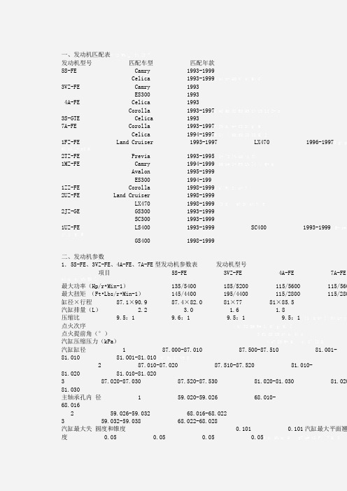
一、发动机匹配表发动机型号匹配车型匹配年款5S-FE Camry 1993-1999Celica 1993-19993VZ-FE Camry 1993ES300 19934A-FE Celica 1993Corolla 1993-19973S-GTE Celica 19937A-FE Corolla 1993-1997Celica 1994-19971FZ-FE Land Cruiser 1993-1997 LX470 1996-19972TZ-FE Previa 1993-19951MZ-FE Camry 1994-1999Avalon 1995-1999ES300 1994-1991ZZ-FE Corolla 1998-19992UZ-FE Land Cruiser 1998-1999LX470 1998-19992JZ-GE GS300 1993-1999SC300 1993-19991UZ-FE LS400 1993-1999 SC400 1993-1999 GS400 1998-1999二、发动机参数1.5S-FE、3VZ-FE、4A-FE、7A-FE型发动机参数表发动机型号项目 5S-FE 3VZ-FE 4A-FE 7A-FE最大功率(Hp/r•Min-1) 135/5400 185/5200 115/5600 115/560最大扭矩(Ft•Lbs/r•Min-1) 145/4400 195/4400 115/2800 115/280缸径×行程87.1×90.9 87.4×82.0 81×77 81×85.5汽缸排量(L) 2.2 3.0 1.6 1.8压缩比 9.5:1 9.6:1 9.5:1 9.5:1点火次序点火提前角(°)汽缸压缩压力(kPa)汽缸缸径 1 87.000-87.010 87.500-87.510 81.001-81.010 81.001-81.0102 87.010-87.020 87.510-87.520 81.010-81.020 81.010-81.0203 87.020-87.030 87.520-87.530 81.020-81.030 81.020 81.030主轴承孔内径 1 59.020-59.026 68.010-68.0162 59.026-59.032 68.016-68.0223 59.032-59.038 68.022-68.028汽缸最大失圆度和锥度 0.101 0.101汽缸最大平面翘度 0.05 0.05 0.05 0.05汽缸盖最大翘曲度汽缸体面 0.05 0.099 0.05 0.05进排气歧管面 0.08 0.099 0.10 0.10气门座宽度进气门 0.99-1.40 0.99-1.40 1.0-1.4 1.0-1.4排气门 0.99-1.40 0.99-1.40 1.0-1.4 1.0-1.4气门座锥角(°) 45 45 45 45气门导管汽缸盖孔内径进气门(1) 11.000-11.027 11.026(许用极限) 11.026(许用极限)排气门 11.000-11.027 11.026(许用极限) 11.026(许用极限)气门导管内径 6.010-6.030 6.010-6.030 6.010-6.029 6.010-6.029气门杆到导管油隙进气门标准值 0.025-0.060 0.025-0.060 0.025-0.061 0.025-0.061许用极限 0.080 0.080 0.08 0.08排气门标准值 0.030-0.065 0.030-0.065 0.030-0.066 0.030-0.066许用极限 0.099 0.099 0.10 0.10气门锥角(°) 44.5 44.5 45 45气门边缘厚度(极限值)进气门 0.50 0.50 0.50 0.50排气门 0.50 0.50 0.50 0.50气门整修长度进气门(使用极限) 97.10 94.60 86.95 86.95排气门(使用极限) 98.00 94.40 87.35 87.35气门杆直径进气门 5.970-5.985 5.970-5.985 5.969-5.985 5.969-5.985 排气门 5.965-5.980 5.965-5.980 5.96-5.98气门间隙进气门 0.19-0.28 0.13-0.23 0.15-0.25 0.15-0.25排气门 0.28-0.38 0.27-0.37 0.25-0.35 0.25-0.35气门弹簧自由长度 41.96-41.99 41.40 38.57 38.57负载长度 16.7-19.5kg/34.70 17.2-19.1kg/33.30 16.9kg/31.7(气门关闭) 16.9kg/31.7(气门关闭)不垂直度 2.00 2.00 2.0 2.0进气凸轮轴轴向间隙(2)标准值 0.046-0.099许用极限 0.120排气凸轮轴轴向间隙(2)标准值 0.030-0.085 0.035-0.090 0.035-0.090许用极限 0.099 0.10 0.10凸轮轴轴向间隙(3)标准值 0.033-0.080许用极限 0.120齿轮背隙标准值 0.020-0.200 0.020-0.200许用极限 0.300 0.300 0.30 0.30凸轮轴轴颈直径 26.959-26.975 26.949-26.965 24.949-24.965(排气凸轮轴1号轴径)22.949-22.965(其它轴径) 24.949-24.965(排气凸轴1号轴径)22.949-22.965(其它轴径)凸轮轴最大径向圆跳动 0.040 0.060凸轮轴轴颈油隙标准值 0.025-0.062 0.035-0.072 0.03 0.072 0.035-0.072使用极限 0.099 0.099 0.10 0.10凸轮轴凸高度进气标准值 42.010-42.110 42.160-42.260 41.910-42.010 41.910-42.010使用极限 41.900 42.010 41.50 41.50排气标准值 40.060-40.160 41.960-42.060 41.960-42.060 41.960-42.060 使用极限 39.950 41.810 41.55 41.55挺杆孔直径 31.000-31.018 31.000-31.018 31.000-31.025 31.00 31.025挺杆直径 30.966-30.976 30.966-30.976 30.966-30.976 30.966-30.976挺杆油隙标准值 0.024-0.052 0.020-0.052 0.024-0.059 0.024-0.059 许用极限 0.070 0.080 0.07 0.07曲轴轴向间隙标准值 0.020-0.220 0.020-0.220 0.020-0.221 0.020-0.221使用极限 0.300 0.300 0.300 0.300曲轴径向圆跳动 0.060 0.060 0.050 0.050主轴承轴颈直径 0 54.998-55.003 63.996-64.000 47.99 48.000 47.994-48.000 1 54.993-54.998 63.990-63.996 47.988-47.994 47.988-47.9942 54.988-54.993 63.986-63.990 47.982-47.988 47.982-47.988主轴径失圆度 0.020 0.020 0.020 0.020主轴径锥度 0.020 0.020 0.005 0.005主轴承油隙(3号轴径)标准曲轴标准值 0.025-0.044 0.028-0.056 0.015-0.033 0.015-0.033许用极限 0.080 0.080加大0.25 标准值 0.027-0.067 0.028-0.080许用极限 0.080 0.080主轴承油隙(除3号轴径)标准曲轴标准值 0.015-0.034 0.028-0.056 0.015-0.033 0.015-0.033许用极限 0.080 0.080加大0.25 标准值 0.019-0.059 0.028-0.080许用极限 0.080 0.080主轴承厚度(3号主轴承)1 1.9920-1.9950 1.989-1.9922 1.9950-1.9980 1.992-1.9953 1.9980-2.0010 1.995-1.9984 2.0010-2.0040 1.998-2.0015 2.0040-2.0070 2.001-2.004主轴承厚度(其它主轴承) 1 1.9970-2.0000 1.989-1.9922 2.0000-2.0030 1.992-1.9953 2.0030-2.0060 1.995-1.9984 2.0060-2.0090 1.998-2.0015 2.0090-2.0120 2.001-2.004连杆轴承厚度 1 1.484-1.488 1.484-1.488 1.486-1.490 1.486-1.4902 1.488-1.492 1.488-1.492 1.490-1.494 1.490-1.4943 1.492-1.496 1.492-1.496 1.494-1.498 1.494-1.498连杆轴承轴颈直径 51.985-52.000 54.986-55.000 39.985-39.999 47.985-48.000连杆轴承失圆度和锥度 0.020 0.020 0.005 0.005连杆轴承油隙标准曲轴标准值 0.024-0.055 0.028-0.065 0.020-0.051 0.020-0.051许用极限 0.080 0.080 0.078 0.078加大0.25 标准值 0.023-0.069 0.028-0.080许用极限 0.080 0.080连杆孔直径(小头销孔) 22.005-22.017 22.005-22.014连杆最大弯曲度 0.05/100.1 0.05/100.1 0.05/100.1 0.05/100.1连杆最大扭曲度 0.150/100.1 0.150/100.1 0.05/100.1 0.05/100.19连杆侧隙标准值 0.160-0.312 0.150-0.330 0.015-0.250 0.015-0.250许用极限 0.350 0.38 0.300 0.300活塞与汽缸间隙标准值 0.140-0.160 0.130-0.150 0.08 0.105 0.085-0.105许用极限 0.180 0.170 0.13 0.13活塞直径 1 86.850-86.860 87.360-87.370 80.905-80.915 80.905-80.9152 86.860-86.870 87.370-87.380 80.915-80.925 80.915-80.9253 86.870-86.880 87.380-87.390 80.925-80.935 80.925-80.935活塞销直径 21.997-22.009 21.997-22.006连杆配合标准值 0.005-0.011 0.005-0.010使用极限 0.050 0.050活塞环侧隙第一道气环 0.040-0.080 0.010-0.080 0.045-0.090 0.045-0.090第二道气环 0.030-0.070 0.030-0.070 0.030-0.071 0.030-0.071活塞环开口间隙第一道气环标准值 0.270-0.500 0.280-0.500 0.25 0.45 0.25-0.45使用极限 1.100 1.100 1.07 1.07第二道气环标准值 0.350-0.600 0.380-0.600 0.35-0.50 0.35-0.50使用极限 1.200 1.200 1.20 1.20油环标准值 0.200-0.550 0.150-0.570 0.15-0.45 0.15-0.45使用极限 1.150 1.170 1.05 1.05机油泵外转子与泵壳间隙标准值 0.099-0.160 0.099-0.175 0.080-0.180 0.080-0.180使用极限 0.200 0.300转子顶隙标准值 0.040-0.160 0.110-0.240 0.025-0.085 0.025-0.085使用极限 0.200 0.350 0.35 0.35转子侧隙标准值 0.030-0.090 0.025-0.085 0.025-0.085使用极限 0.150注:(1)气门导管汽缸盖孔内径进气门 Camry 标准气门导管 11.000-11.027加大气门导管 11.050-11.077Celica 标准气门导管 10.985-11.012加大气门导管 11.035-11.062排气门 Camry 标准气门导管 11.000-11.027加大气门导管 11.050-11.077Celica 标准气门导管 10.985-11.012加大气门导管 11.035-11.062(2)对于双凸轮轴。
丰田86 TRD v 大众高尔夫 GTI PP

丰田86 TRD v 大众高尔夫 GTI PP作者:暂无来源:《汽车与运动》 2014年第2期一驾驶员为绝对核心的日本跑车,和一辆完全不同的德国掀背钢炮放在一起,同样都是高性能版车型,谁会更出色?文/Jethro Bovingdon 摄影/Dean Smith 译/张磊 @张磊Ray-ZThis month本月推介斯巴鲁BRZv 大众Scirocco GTS日系后驱对战德系前驱,86和GTI也不能袖手旁观奔驰S63 AMG Lv 捷豹XJR两辆高性能豪华车的对决,谁更有驾驶乐趣一些?路虎混合动力版揽胜动力爆发更迅猛,减排效果更明显日产GT-R更加精致优雅,使用更方便的性能机器大众全新高尔夫GTI它传承经典设计,却不止于传承经典设计长城哈弗H810万元是本土品牌的价格门槛?长城扬言挑战20万元沃尔沃S60LS60L需要用心去感受,方能体会其中北欧幸福味道沃尔沃V40它绝对算得上是一个另类钢炮,优雅且激进The test team测试团队虽然推迟了3个月,但长城汽车仍旧自信满满地推出了哈弗H8,一轮“值与不值”的讨论激战正酣,我们该怎么看待这款中大型SUV呢?程志明执行主编 Editor-In-ChiefH8的推出是长城多年来技术与品牌累积的必然,也是长城作为自主品牌非常大胆的一步,从配置、技术和性能方面来讲,20多万还是超值的。
莽超执行副主编 Deputy Editor-In-Chief车是好车,但价格不能跟大小简单地划上等号。
从账面上看,它是自主SUV的旗舰,况且品质还在持续提升。
值与不值,我想三个月后再做结论。
朱峥试车编辑 Editor长城汽车久经沙场后终于厚积薄发。
可我一直有个疑问:先有20万元再有哈弗H8,还是先有哈弗H8再有20万元?我宁愿相信是后者。
吕思达试车编辑 Editor长城H8的推出是自主品牌的一个突破,对于H8的配置和尺寸来说20万左右的售价还算合理,但是否能得到消费者的认可,还有待市场验证。
chassis交换机硬件架构---S86交换机硬件架构
模块层
进风层:位于模块层之下。 出风层:风扇盘位于模块层之上,为系
统的出风系统;采用垂直散热。
进风层
电源层
7
RG-S8614
液晶屏
模块层:提供14个模块插槽;其中管理 板插槽2个,线卡插槽12个。
出风口(背面)
电源层:最大支持两个AC电源或者两 模块层 个DC电源;支持1200W和2000W的
RG-S8600为全模块设计,所有的管理模块、交换 模块、电源、风扇盘和液晶屏都可以支持热插拔, 目前有三个型号的主机:
• RG-S8606 • RG-S8610 • RG-S8614
4
RG-S8600交换机特点
• 高可靠性设计和维护性:线卡、电源、风扇等支持热插拔;电源 设计1+1冗余,管理板支持冗余。
12gbpsin12gbpsoutperhigig议程23s8600交换机主机s8600交换机管理板架构s8600交换机线卡架构s8600交换机整机架构s8600交换机数据处理流程s86交换机整机硬件架构24cpucpu内部通信模块100basetusb芯片fabricsdram并行flash串行flashcpldio接口cpucpu内部通信模块100basetusb芯片fabricsdram并行flash串行flashcpldio接口cpucpusdramcpldio接口内部通信模块100basetfabricmacphy并行flash串行flash线卡acpucpusdramcpldio接口内部通信模块100basetfabricmacphy并行flash串行flash线卡b管理板m1管理板m2pci总线系统总线higig接口其他连线内部以太网背板higig背板以太网s86交换机整机硬件架构特点整机包括无源背板电源模块风扇模块液晶模块以及管理板和线卡
NSI DIGITAL DIMMING SYSTEM 86 88 96 9800 电源控制系统说明书
NSI DIGITAL DIMMING SYSTEM INSTALLATION AND OPERATION GUIDE Software Revision 1.41, Version C UL, Mfg Q3/96, and above SPECIFICATIONS NSI DIGITAL DIMMING SYSTEMDDS 86/88/96/9800 DIMMER PACKSINSTALLATION AND OPERATION GUIDESoftware Revision 1.41, Version C UL, Mfg Q3/96, and above SPECIFICATIONSNumber of Channels:86/9600 : 6 channels88/9800 : 8 channelsOutput capacity:86/8800 : 1200 watts (120v) per channel.96/9800 : 2400 watts (120v) per channel.Input Power:8600 : 120/208 V ac, 3 phase, 4 wire 20 A or120/240 V ac, 1 phase, 3 wire 30 A8800 : 120/240 V ac, 1 phase, 3 wire 40 A9600 : 120/208 V ac, 3 phase, 4 wire 40 A or120/240 V ac, 1 phase, 3 wire, 60 A9800 : 120/240 V ac, 1 phase, 3 wire, 80 ADimmer control system:Microprocessor digital phase control dimming orzero-crossing relay mode.Load filtering:~ 500us rise time.Control Input Types:0 - 10VDC each channel on 9 pin ‘‘D’’ connector.MICROPLEX multiplex signal (128 channel) onthree pin XLR type connector.DMX-512 digital signal (512 channel)on five pin XLR optional.Control Wiring:Class 2 low voltage.Output Connections:NEMA 5-15 or 5-20 duplex per ch. standard.Several other types are optional.Cooling System:Thermostatically controlled variable speed fan-forced air with intake on front panel,exhausting on sides of dimmer.MOUNTINGThe NSI DDS rack mountable dimmers are designed to be mounted in a standard 19" EIA rack. The packs are provided with two mounting flanges or ‘‘ears’’ designed for securing to the front rack mounting rails.The optional REAR SUPPORT KIT must be used in all cases where the rack is portable and prone to bumps and rough handling.The NSI DDS rack dimmers depend upon forced air cooling. The rack enclosure shall allow a 2 in. clearance on each side of the dimmer to insure adequate air exhaust. In some cases where exhaust air flow is obstructed, additional exhaust fans should be used to remove hot air from the rack. Free flow of room air to the front of the dimmer packs must be insured. Any front cover on the rack must be removed during operation. Keep the air vents located on the front and each side of the dimmer pack clear of dust or any obstructions.If units are to be operated in a small enclosed room, adequate ventilation must be provided to prevent the room temperature fromexceeding 100 degrees fahrenheitAC Lighting Loads, Only.For Indoor Use OnlyUtilizer Dans Un Endroit A L’AbriINSTALLATION AND OPERATION GUIDEDDS 86/88/96/9800 DIMMER PACKS MOUNTING Software Revision 1.41, Version C UL, Mfg Q3/96, and aboveDDS 86/88/96/9800 DIMMER PACKS INSTALLATION AND OPERATION GUIDESoftware Revision 1.41, Version C UL, Mfg Q3/96, and aboveINPUT POWER WIRINGThe NSI DDS rack dimmers must be provided with a proper electrical service as listed below:*8600 : 120/240 VAC 20 amp 3 pole 4 wire plus ground (use minimum #10 AWG) or120/240 VAC 30 amp 2 pole 3 wire plus ground (use minimum #8 AWG).8800 : 120/240 VAC 40 amp 2 pole 3 wire plus ground only (use minimum #6 AWG).*9600 : 120/240 VAC 40 amp 3 pole 4 wire plus ground (use minimum #4 AWG) or120/240 VAC 60 amp 2 pole 3 wire plus ground (use minimum #4 AWG).9800 : 120/240 VAC 80 amp 2 pole 3 wire plus ground only (use minimum #2 AWG).* Unit set up for 3 pole 4 wire - for 2 pole 3 wire operation see Service Manual.Input wiring must be copper wire rated at least 90C and must be protected by a suitable branch circuit breaker. Wire sizes show above in parenthesis are for type S, SO,or similar cords. Other types of cords or cables should be sized according to local electrical codes.All wiring should be done by qualified personnel only!WARNING: Do not connect chassis ground to NEUTRAL or operate without a chassis ground. To do so may allow exposure to potentially lethal voltage levels and will void the warranty on this product.INSTALLATION AND OPERATION GUIDE DDS 86/88/96/9800 DIMMER PACKSSoftware Revision 1.41, Version C UL, Mfg Q3/96, and aboveAC OUTPUT RECEPTACLESThe standard version of the DDS rack dimmers have two AC output receptacles for each channel. These receptacles provide power to the lamps in your lighting system. The amount of power supplied to these outlets controls the intensity of the lamps connected. The total lamp wattage connected to each channel must not exceed the rating of each channel (see specifications). Most 120VAC lamps and fixtures and some transformer type low-voltage fixtures may be connected to these outlets, DO NOT connect motors or fluorescent lighting to these outlets when the channel is operating in dimmer mode.NOTE: Some inductive type loads such as transformers, ballasts, and motors, with poor power factor may cause the dimmer to output D.C. type current. This may cause the load to draw excessive current and overheat, causing damage to the transformer, ballast, or motor. For this reason, it is necessary to insure any inductive loads are fused individually for their respective normal operating current.MICROPLEX MULTIPLEX CONTROL WIRINGMicroplex is the control protocol used on most NSI lighting consoles. This system uses a single three conductor cable to transmit up to 128 channels of dimmer control. For short distances (50 feet or less) a standard microphone cable may be used to carry both the control signal and the DC power source for NSI control consoles. Longer distances may be accommodated with 18 gauge or better cable to reduce voltage losses of the power supply.Connect the Microplex control cable to either of the three pin XLR jacks. Since both jacks are wired in parallel, another control cable may be connected between the remaining jack and another dimmer pack. Many dimmer packs may be ‘‘daisy chained’’together in this manner.Be sure to set the Channel Address dip switch as required (see MPX ADDRESS SWITCH SETTINGS).ANALOG 0 - 10 VDC CONTROL WIRING.Each of the dimmer channels of the NSI DDS rack dimmer pack may be operated by an analog 0 - 10 VDC control voltage. This type of control will provide 0% intensity at 0 volts and 100% intensity at 10 volts. Any or all of the DDS rack dimmer channels may be operated in this manner simultaneously with any multiplex control input. Each dimmer will respond to the greater of any control inputs.The analog control input uses a standard 9 pin ‘‘D’’ connector which is available from most electronics and computer supply houses.Connect each of the positive channel control wires to the desired dimmer channel input pins (see diagram below) of the plug.Connect the common (ground) control wire to the pin indicated on the diagram. Consult the documentation of the analog control console or device you are using for the proper connections. The control input impedance is 4.7K ohms.When using analog inputs, Dipswitch #10 should be in the up position to disable Channel Level Memory.DDS 86/88/96/9800 DIMMER PACKSINSTALLATION AND OPERATION GUIDE Software Revision 1.41, Version C UL, Mfg Q3/96, and above MICROPLEX MULTIPLEX CONTROL WIRINGINSTALLATION AND OPERATION GUIDE DDS 86/88/96/9800 DIMMER PACKSDMX 512 multiplex control wiring Software Revision 1.41, Version C UL, Mfg Q3/96, and aboveDMX 512 multiplex control wiringDMX 512 is the United States Institute of Theater Technology (USITT) standard for the digital control of dimmers. NSI DDS Dimmer products can be converted from Microplex to DMX 512 digital multiplex with a simple kit available from your dealer.DMX-512 is the preferred type of control wiring when many dimmer channels are used, because of the high update rate and the resistance to interference. It is recommended in locations subject to electrical noise. DMX-512 only requires 3 wires to transmit lighting levels for as many as 512 dimmer channels. Most of the NSI lighting control consoles can optionally use this interface.Connect the DMX 512 cable from the control console to the male input connector. Another cable may be connected from the female connector to the male connector on another pack. Many dimmer packs may be ‘‘daisy chained’’ and connected together in this manner. Be sure to set the Channel Address dip switch as required (see MPX ADDRESS SWITCH SETTINGS).LED INDICATORSPWR (Green) - Indicates the +5 volt power supply of the dimmer is operating.LINE 1, 2, 3 (Green) - Indicates the respective pole of the input power is energized. A blown fuse on an internal power supply transformer may cause one of these LEDs to not light. When a 3 pole dimmer is wired for 2 pole operation, the LINE 2 LED will not light.MPX (Green) - Indicates presence of multiplex signal when steady.TEMP (Red) - Steady indicates the dimmer is too hot and is preparing to shut down. Flashing indicates the dimmer has reduced levels or is shutting down in order to lower internal operating temperatures. (See FAN OPERATION and OVER TEMPERATURE.) CTL STAT (Green) Indicates the relative control level for each channel.NO LOAD (Yellow) Steady indicates the absence of a load on a particular channel output. This may be due to no connection to the output or a faulty lamp. Flashing of the NO LOAD LED indicates that the respective channel is in the Focus Test Mode and is forced to full intensity.NOTE: Load ‘‘sensing’’ does not operate when the dimmer channel is above 75% intensity or in the Focus Test mode. The No Load indicator is only reliable when the dimmer channel control is off or below 75% and the respective circuit breaker is on.LAMP FOCUS TESTPressing the FOCUS TEST button for any channel will force the control for that channel to full on and cause the NO LOAD LED to flash. Pressing the button a second time will cause the channel to return to normal control.CHANNEL CIRCUIT BREAKERSEach channel is protected by a magnetic circuit breaker to help prevent overloading the power control devices used in the dimmer.These circuit breakers also function as master power switches for each channel.Note: Lamps may sometimes cause a temporary ‘‘short-circuit’’ when the filament burns out and cause the circuit breaker to trip. This is normal and protects the internal dimmer circuitry from damage.CHANNEL LEVEL MEMORY.Whenever dipswitch #10 is in the off (down) position and there is a loss of multiplex signal detected, all channel outputs will remain at the last received intensity level. If dipswitch #10 is in the up position, all lights will go out on loss of multiplex. The automatic sequencing feature must be disabled for Channel Level Memory to operate (see INTERNAL JUMPER / DIPSWITCH SELECTIONS).FAN OPERATION and OVER TEMPERATUREThe NSI DDS rack dimmer packs employ a highly efficient cooling system and variable speed temperature controlled fan which functions as follows:•When the dimmer pack is first powered up the fan will immediately come to full speed for two seconds for self test and then will shut off providing the dimmer is at room temperature.•(NOTE: The fan may run at very low speed when dimmer is idle and at room temperature.)•As the dimmer pack warms up when lighting loads are turned on, the fan will turn on at a slow speed and gradually increase in speed as more cooling is needed. This reduces unnecessary fan noise and dust collection.•If for some reason the dimmer airflow is blocked or inadequate the TEMP LED will light.•If temperature rises any further, the dimmer will attempt to reduce all lighting levels by 25% increments in order to reduce temperature. The TEMP LED will start flashing.•If internal temperature still rises, a thermostat will shut off all output. The TEMP LED will flash.Overheating of the dimmer is not normal and may be due to restriction of air circulation, or fan failure.To adjust the temperature sensing of the DDS 88/9800( 86/9600 ) dimmers please see below;IMPORTANT: BE SURE DIMMER PACK AT ROOM TEMPERATURE!!1. Activate the calibration mode by holding down focus test switchs 4 and 8 ( 3 and 6 ) together for about 6 seconds.You will notice the fan runs at high speed , the line indicator LEDs begin to flash and the temp LED is on. NOTE: If the temp led is off no calibration is required.2. Press focus test switch 2 ( 1 ) if calibration is low or focus test switch 3 ( 2 ) if high.You will notice the temp load indicator LED should go off indicating proper calibration.3. Press focus test switch 4 and 8 ( 3 and 6 ) together to exit the temperature calibration mode.DDS 86/88/96/9800 DIMMER PACKSINSTALLATION AND OPERATION GUIDE Software Revision 1.41, Version C UL, Mfg Q3/96, and above LAMP FOCUS TESTINSTALLATION AND OPERATION GUIDE DDS 86/88/96/9800 DIMMER PACKSMPX ADDRESS SWITCH SETTINGS Software Revision 1.41, Version C UL, Mfg Q3/96, and aboveMPX ADDRESS SWITCH SETTINGSWhen using any of the multiplex control systems the dip switches on the front panel of the DDS rack dimmer must be set to assign the desired dimmer channels. The switches set the dimmer pack’s starting address to any channel from 1 to 512 (128 for Microplex). See the following chart for settings.For channels 1 - 128 set dipswitch #8 and #9 off and #1-7 as below.Starting Ch.1234567Starting Ch.1234567 Starting Ch.123456710000000210000003 010000041100000500100006 101000070110000811100009 000100010100100011010100012 110100013001100014101100015 011100016111100017000010018 100010019010010020110010021 001010022101010023011010024 111010025000110026100110027 010110028110110029001110030 101110031011110032111110033 000001034100001035010001036 110001037001001038101001039 011001040111001041000101042 100101043010101044110101045 001101046101101047011101048 111101049000011050100011051 010011052110011053001011054 101011055011011056111011057 000111058100111059010111060 110111061001111062101111063 011111064111111065000000166 100000167010000168110000169 001000170101000171011000172 111000173000100174100100175 010100176110100177001100179 101100179011100180111100181 000010182100010183010010184 110010185001010186101010187 011010188111010189000110190 100110191010110192110110193 001110194101110195011110196 111110197000001198100001199 010001110011000111010010011102 101001110301100111041110011105 000101110610010111070101011108 110101110900110111101011011111 011101111211110111130000111114 100011111501001111161100111117 001011111810101111190110111120 111011112100011111221001111123 010111112411011111250011111126 101111112701111111281111111For channels 129 - 256 Set dipswitch 1-7 as above and set dipswitch #8 on and #9 off.For channels 257 - 384 Set dipswitch 1-7 as above and set dipswitch #8 off and #9 on..For channels 385 - 512 Set dipswitch 1-7 as above and set dipswitch #8 and #9 on.For dipswitch # 10 setting see CHANNEL LEVEL MEMORY.DDS 86/88/96/9800 DIMMER PACKS INSTALLATION AND OPERATION GUIDESoftware Revision 1.41, Version C UL, Mfg Q3/96, and above INTERNAL JUMPER / DIPSWITCH SELECTIONSINTERNAL JUMPER / DIPSWITCH SELECTIONSCaution: The follow procedures should be performed by qualified personnel only.Remove all power and remove the cover of the dimmer pack. Locate and change jumper or dipswitch settings on the firing card as indicated in the following section.SoftstartThe Softstart mode of operation forces at least a 1/10th second delay between the output being full off to the output being full on to allow a more gradual warming of the lamp filaments. Thermal shock and inrush currents are reduced thereby increasing lamp life. Softstart should not be used when quick dimmer response is desired such as chasing.To activate Softstart; remove the jumper block from the pin marked J1 on the firing card or move internal dipswitch S10 to the off position. Replacing the jumper block or turning the switch on will deactivate Softstart.NOTE: The channels of the DDS rack dimmer pack configured for NON DIM operation will not be affected by softstart.Non Dim Channels (Relay Mode)Any of the channels of the DDS rack dimmer pack may be configured as NON DIM channels. This will cause the output of the channel to go to full on whenever the input signal is over 15%. When the input signal drops to less than 10%, the channel output goes to full off. This is the equivalent of a zero-crossing solid state relay.To configure a channel for NON DIM operation simply remove the jumper block from the pins on the firing card as indicated or turn the switch indicated OFF. Replacing the jumper block or turning the switch ON will restore dimming operation.CHANNEL SWITCH JUMPER CHANNEL SWITCH JUMPER1 S1 J102 S2 J93 S3 J84 S4 J75 S5 J6 6 S6 J57 S7 J4 8 S8 J3SWITCH OR JUMPER OFF = NON DIMSWITCH OR JUMPER ON = DIMMERINSTALLATION AND OPERATION GUIDE DDS 86/88/96/9800 DIMMER PACKSAUTO SEQUENCING MODE Software Revision 1.41, Version C UL, Mfg Q3/96, and aboveAUTO SEQUENCING MODEThe DDS rack dimmers can be configured to perform stand alone Automatic Sequencing in place of Channel Level Memory. This is useful for lighting displays and show windows. The eight channels will automatically fade from one to another in a preprogrammed pattern and time selected by the front panel dipswitch whenever dipswitch #10 is down and no multiplex signal is detected. The Analog control input will continue to operate while the dimmer is sequencing.To enable Automatic Sequencing Mode remove jumper from position J2 or turn INTERNAL dipswitch S9 to OFF.Front Panel Dipswitch settingsSTEP TIME SWITCH 1,2,3PATTERN SWITCH 4,5,61 SECOND OFF,OFF,OFF SEQUENCE OFF,OFF,OFF3 SECOND ON,OFF,OFF ODD / EVEN SEQUENCE ON,OFF,OFF5 SECOND OFF,ON,OFF PAIRED SEQUENCE OFF,ON,OFF10 SECOND ON,ON,OFF ODD / EVEN ALT ON,ON,OFF15 SECOND OFF,OFF,ON OUT / IN SEQUENCE OFF,OFF,ON30 SECOND ON,OFF,ON BUILD ON,OFF,ON45 SECOND OFF,ON,ON BUILD +OFF,ON,ON60 SECOND ON,ON,ON RANDOM ON,ON,ONDipswitch # 7 on causes all above sequences to ping-pong.INSTALLATION and OPERATION TIPSCare should always be taken to:1) Keep all AC wiring away from control wiring.2) We also recommend powering up and performance checks be done one unit at a time. This can be a real time saver should problems arise thus eliminating unnecessary isolation techniques to resolve the problem.Technical SupportIf addition help or service is needed, contact your dealer or the NSI Technical Services Hotline: (503) 682-6228.DDS 86/88/96/9800 DIMMER PACKS INSTALLATION AND OPERATION GUIDE Software Revision 1.41, Version C UL, Mfg Q3/96, and aboveWARRANTYNSI Corporation Limited WarrantyNSI Corporation warrants new electronics products to be free from defective materials and workmanship for a period of one (1) year from the date of purchase to the original owner when purchased from an authorized NSI dealer.The purchaser is responsible for completing and mailing to NSI, within 15 days of purchase, the warranty registration card enclosed with each product. NSI products that have been subject to accident, alteration, abuse, or defacing of the serial number are not covered by this warranty. The normal wear and tear of items such as knobs, jacks, and switches are not covered under this warranty.If your NSI product requires service during the warranty period, NSI will repair or replace, at its option, defective materials provided you have identified yourself as the original owner of the product to NSI or any authorized NSI dealer. Transportation charges to and from an authorized dealer or the NSI factory for repair shall be the responsibility of the owner. All products returned to NSI must have factory authorization for return prior to shipping.NSI Corporation is not liable for any incidental or consequential damages resulting from defect or failure other than repairs of the NSI product subject to the terms of this warranty. This warranty gives you specific legal rights, and you may have other rights which vary from state to state. This warranty is expressly in lieu of all other agreements and warranties expressed or implied except as may be otherwise required by law.INSTALLATION AND OPERATION GUIDE DO NOT INCLUDE THIS PAGE WITH THE COPIESSoftware Revision 1.41, Version C UL, Mfg Q3/96, and aboveDate Revision6/28/96Manual update for external temp cal as per rel 1.41DO NOT INCLUDE THIS PAGE WITHTHE COPIES。
丰田旗下车辆平台详解
[原创]不算平台的平台丰田旗下车辆平台详解2012-07-30 16:27爱卡汽车梁伯苓分享第 1 页:什么是平台?[XCAR 导购原创]近些年来,由于大众集团对车架平台概念的推进的努力,再加上大众集团在国内汽车业界有着非同凡响的影响力的缘故,相当多的国内车迷朋友都已经熟知了大众集团的平台概念。
但事实上,由于内部管理方式、研发和生产习惯的不同,几乎每家车厂对于所谓“平台(Platform)”的概念都有着自己专门的阐述和定义,如果用大众集团的平台概念去生搬硬套到其他车厂身上,那显然就会造成很多不严谨之处。
首先我们来解释下平台——什么?你说笔者来凑字数了?那您还是看完这段再说吧,说不定有点有价值的信息——“平台”这个词的英文是Platform,“Platform”这个字有相当多的意思,在汽车领域的定义演化自于建筑学方面的定义,在建筑学领域,这个词指的是建筑物的构造、设计、具体工程制造方式等组成的一个综合概念,而在汽车行业通常则指的是底盘或者车架、副车架、悬挂、转向系统、动力总成等组成的一个综合概念。
【平台是底盘、车架、悬挂、转向、动力总成等组成的一个综合概念】而谈及丰田自动车对于平台的定义和阐述,我们当然要说说日语里的具体情况,在日本人口中,平台这个词通常叫做“プラットフォーム”,这个字是英语里的“Platform”的日语音译(当然,你懂的,这个日语词读起来并不像是英语)。
但在日语中,车身平台的这个字,在一些情况下还可以写成“共通シャシ”(注2),这个词的意味就与英语中“Platform”的通常意味多少存在了一定的差别。
但问题在于,“プラットフォーム”和“共通シャシ”这两个词虽然在日语里不是什么完全意义上的同义词,但在翻译成英语的时候,大多数情况下(包括丰田自动车自己提供的英文资料中也是)都会被不加区别的直接翻译成意指车身平台的“Platform”——现在知道为什么好多人说日语是种暧昧的语言了吧?反正日本人的语言里,经常就是既然让你搞不清楚,干脆就绕糊涂你。
chassis交换机硬件架构---S86交换机硬件架构
11
管理板前面板
Status
RJarm
串口
• 从左到右3盏LED指示灯:Status,Primary,Alarm。 Status:启动过程中绿色闪烁,正常运行时恒绿,复位时红色
。
Primary:绿色亮表示本板为主管理板,灯灭表示为从板。 Alarm:告警灯,红色亮表示有异常。 一般情况下:风扇故障、线卡无法启动等异常,该灯都会显示
HiGig接口
I/O接口
内部通信模块:
其他连线
CPLD
扩展出一个内部Fa交br换ic 机,通过100Base-T接 100Base-T
口建立用于管理模块和线卡模块间通讯的内
部百兆以太网系统,用于网管信息的传输。
CPLD(中心逻辑控制模块):
背板接插件
收集系统背的板外接插围件信息;根据CPU的指令背发板接出插各件
电源;两个电源之间形成冗余备份, 同时提供均流功能。
进风口
进风口:位于模块层的两侧。 出风层:风扇盘位于机箱后部。
电源层
8
机箱与部件的配套说明
M8606-CM
M8606-CMII
M8610-CM M8610-CMII M8614-CMII M8600系列线卡 M8606-FAN M8610-FAN M8614-FAN PA1200/PA1200E PA2000/PD1200 PD2000
S86交换机硬件架构
1
• 课程目标
介绍S8600交换机硬件构成及工作原理。
• 课程时间
0.75h
• 培训验收方式
完成培训
2
议程
S8600交换机主机 S8600交换机管理板 S8600交换机线卡 S8600交换机整机架构 S8600交换机数据处理流程