实验六 广域网协议封装与验证配置
广域网协议的封装

广域网协议的封装协议名称:广域网协议的封装一、目的和范围本协议旨在规定广域网(Wide Area Network,简称WAN)协议的封装方式,以实现数据在广域网中的传输和交换。
本协议适用于广域网设备之间的通信。
二、术语定义1. 广域网(Wide Area Network,WAN):指覆盖广范围的网络,由多个局域网(Local Area Network,LAN)相互连接而成。
2. 协议封装(Protocol Encapsulation):指在数据传输过程中,将上层协议的数据包封装到下层协议的数据包中,以实现数据在不同网络之间的传输。
三、协议封装方式1. 数据链路层封装广域网协议的封装在数据链路层进行,主要包括以下步骤:a. 帧封装:将上层协议的数据包封装到数据链路层的帧中,添加帧头和帧尾等必要字段。
b. MAC地址封装:在帧头中添加源MAC地址和目的MAC地址,以标识数据包的发送和接收方。
c. 网络类型封装:在帧头中添加网络类型字段,指明数据包所属的网络类型(如以太网、ATM等)。
d. CRC校验封装:在帧尾中添加CRC校验字段,用于检测数据传输过程中的错误。
2. 网络层封装广域网协议的封装在网络层进行,主要包括以下步骤:a. IP封装:将数据链路层的帧中的数据包提取出来,封装到网络层的IP数据包中。
b. 源IP地址和目的IP地址封装:在IP数据包头部添加源IP地址和目的IP 地址,以标识数据包的发送和接收方。
c. TTL封装:在IP数据包头部添加TTL(Time to Live)字段,用于限制数据包在网络中的生存时间。
d. IP选项封装:根据需要,可以在IP数据包头部添加一些可选字段,如记录路由信息等。
3. 传输层封装广域网协议的封装在传输层进行,主要包括以下步骤:a. TCP/UDP封装:将网络层的IP数据包提取出来,封装到传输层的TCP或UDP数据包中。
b. 源端口号和目的端口号封装:在TCP或UDP数据包头部添加源端口号和目的端口号,以标识数据包的发送和接收方。
4.1广域网协议封装与PPP的PAP认证

4.1 广域网协议封装与PPP的PAP认证【项目情境】假设你是公司的网络管理员,公司为了满足不断增长的业务需求,申请了专线接入,当客户端路由器与ISP进行链路协商时,需要验证身份,以保证链路的安全性。
也是对ISP进行正常的交费与后续合作的重要保证。
要求链路协商时以明文的方式进行传输。
【项目目的】1.掌握广域网链路的多种封装形式。
2.掌握ppp协议的封装与PAP验证配置。
3.掌握PAP配置的测试方法、观察和记录测试结果。
4.了解PAP以明文方式,通过两次握手,完成验证的过程。
【相关设备】路由器两台、V.35线缆一对。
【项目拓扑】【项目任务】1.如上图搭建网络环境,并对两个路由器关闭电源,分别扩展一个同异步高速串口模块(WIC-2T)。
两个路由器之间使用V.35的同步线缆连接,RouterA的S0/1口连接的是DCE端,RouterB的S0/1口连接的是DTE端。
配置RouterA和RouterB的S0/1口地址。
在RouterA的S0/1口上配置同步时钟为64000。
2.在两个路由器的连接专线上封装广域网协议PPP,并查看端口的显示信息,测试两个路由器之间的联连性。
(封装的广域网协议还有:HDLC、X.25、Frame-relay、ATM,双方封装的协议必须相同,否则不通)3.在两个路由器的连接专线上建立PPP协议的PAP认证,RouterA 为被验证方,RouterB为验证方(即密码验证协议,双方通过两次握手,完成验证过程),并测试两个路由器之间的联连性(明文方式进行密码验证,通过PPP的LCP层链路建立成功,两个路由器才可互通)。
先通过show running-config来查看配置。
4.在RouterB上启用debug命令验证配置,需要把S0/1进行一次shutdown再开启,观察和感受链路的建立和认证过程。
5.最后把配置以及ping的结果截图打包,以“学号姓名”为文件名,提交作业。
6.使用锐捷设备(2、3人一组)完成上面的步骤(端口见如下拓扑图)【实验命令】1.在两个路由器的连接专线上封装广域网协议PPPRouterA(config)#interface serial 0/1RouterA(config-if)#encapsulation pppRouterB(config)#interface serial 0/1RouterB(config-if)#encapsulation ppp2.查看封装端口的显示信息RouterA#show interfaces serial 0/13.在两个路由器的连接专线上建立PPP协议的PAP认证RouterA(config)#interface serial 0/1RouterA(config-if)#ppp pap sent-username RouterA password 0 123RouterB(config)#username RouterA password 0 123RouterB(config)#interface serial 0/1RouterB(config-if)#ppp authentication pap4.在RouterB上启用debug命令RouterB#debug ppp authenticationRouterB#debug ppp negotiation5.把RouterB 的S0/1进行一次shutdown再开启,观察和感受链路的建立和认证过程。
广域网协议封装与验证实验

10级计网贺建广域网协议封装与验证实验实验背景:你是公司的网络管理员,两个分公司之间希望能够申请一条广域网专线进行连接。
现有思科路由器设备,希望你了解该设备的广域网接口所支持的协议,以确定选择哪种广域网链路。
公司为了满足不断增长的业务需求,申请了专线接入,你的客户端与ISP进行链路协商时要验证身份,配置路由器保证链路建立,并考虑其安全性。
实验步骤:串行链路均采用PPP封装;路由器之间的链路采用CHAP验证和PAP验证;路由协议均采用动态RIP协议。
任务1:配置路由器接口网关地址,设置串行链路的时钟频率。
任务2:配置动态路由协议。
任务3:验证连通性。
任务4:配置链路之间的安全验证。
任务5:测试安全验证的有效性。
实验拓扑:IP地址规划:实验配置过程:1.路由器R0、R1、R2基本配置Router>enRouter#conf tEnter configuration commands, one per line. End with CNTL/Z. Router(config)#host R0R0(config)#int f0/0R0(config-if)#ip add 192.168.1.1 255.255.255.0R0(config-if)#no shutR0(config-if)#exitR0(config)#int s0/0R0(config-if)#ip add 192.168.3.1 255.255.255.252R0(config-if)#clock rate 64000R0(config-if)#no shutR0(config-if)#exitRouter>enRouter#conf tEnter configuration commands, one per line. End with CNTL/Z. Router(config)#host R1R1(config)#int s0/0R1(config-if)#ip add 192.168.3.2 255.255.255.252R1(config-if)#no shutR1(config-if)#exitR1(config)#int s0/1R1(config-if)#ip add 192.168.3.5 255.255.255.252R1(config-if)#no shutR1(config-if)#exitRouter>enRouter#conf tEnter configuration commands, one per line. End with CNTL/Z. Router(config)#host R2R2(config)#int s0/0R2(config-if)#ip add 192.168.3.6 255.255.255.252R2(config-if)#clock rate 64000R2(config-if)#no shutR2(config-if)#exitR2(config)#int f0/0R2(config-if)#ip add 192.168.2.1 255.255.255.0 R2(config-if)#no shutR2(config-if)#exit2.配置路由协议RIP2R0>enR0#conf tR0(config)#router ripR0(config-router)#ver 2R0(config-router)#net 192.168.1.0R0(config-router)#net 192.168.3.0R0(config-router)#exitR1(config)#router ripR1(config-router)#ver 2R1(config-router)#net 192.168.3.0R1(config-router)#net 192.168.3.4R1(config-router)#exitR2(config)#router ripR2(config-router)#ver 2R2(config-router)#net 192.168.3.4R2(config-router)#net 192.168.2.0R2(config-router)#exit3.测试连通性PC0 ping PC1成功!ok4.配置链路安全性R0(config)#int s0/0R0(config-if)#encapsulation pppR0(config-if)#ppp authentication chapR0(config-if)#exitR0(config)#username R1 password ciscoR1(config)#int s0/0R1(config-if)#encapsulation pppR1(config-if)#ppp authentication chapR1(config-if)#exitR1(config)#username R0 password ciscoR1(config)#R1(config)#int s0/1R1(config-if)#encapsulation pppR1(config-if)#ppp auth papR1(config-if)#exitR1(config)#username cisco password 123R2(config)#int s0/0R2(config-if)#encapsulation pppR2(config-if)#ppp pap sent-username cisco password 123 R2(config-if)#exit5.测试安全验证的有效性PC0 ping PC1关闭路由器R1中接口s0/0之后R1#debug ppp authenticationPPP authentication debugging is onR1#conf tEnter configuration commands, one per line. End with CNTL/Z.R1(config)#int s0/0R1(config-if)#shutR1(config-if)#R1(config-if)#no shut%LINK-5-CHANGED: Interface Serial0/0, changed state to upR1(config-if)#Serial0/0 IPCP: O CONFREQ [Closed] id 1 len 10Serial0/0 IPCP: I CONFACK [Closed] id 1 len 10Serial0/0 IPCP: O CONFREQ [Closed] id 1 len 10%LINEPROTO-5-UPDOWN: Line protocol on Interface Serial0/0, changed state to up R1(config-if)#exit关闭路由器R1中接口s0/1之后R1#debug ppp authPPP authentication debugging is onR1#conf tEnter configuration commands, one per line. End with CNTL/Z.R1(config)#int s0/1R1(config-if)#shutR1(config-if)#no shutR1(config-if)#%LINK-5-CHANGED: Interface Serial0/1, changed state to upR1(config-if)#Serial0/1 PAP: I AUTH-REQ id 17 len 15Serial0/1 PAP: Authenticating peerSerial0/1 PAP: Phase is FORWARDING, Attempting Forward%LINEPROTO-5-UPDOWN: Line protocol on Interface Serial0/1, changed state to up 到此广域网协议封装与验证实验完成!。
路由器广域网封装协议步骤说明
路由器广域网封装协议步骤说明实验四:DCR-2626设备telnet密码//路由器设置telnetusername abcd password 0 abcdaaa authentication login default localaaa authentication enable default none实验五:路由器串口PPP协议认证方式。
CHAP方式:R1_config#aaa authentication ppp default local (定义名为shenzhou,本地数据验证的aaa验证方法)R1_config#username R2 password 0 shenzhou(设置账号密码)R1_config#int s0/1R1_config_s0/1#ip add 192.168.1.1 255.255.255.252R1_config_s0/1#physical-layer speed 2048000R1_config_s0/1#encapsulation ppp(封装PPP协议)R1_config_s0/1#ppp authentication chap (设置验证方式)R1_config_s0/1#ppp chap hostname R1(设置发送给对方验证的账号)R2_config#aaa authentication ppp default local(定义名为shenzhou,本地数据验证的aaa验证方法)R2_config#username R1 password 0 shenzhou(设置账号密码)R2_config#int s0/1R2_config_s0/1#ip add 192.168.1.1 255.255.255.252R2_config_s0/1#encapsulation ppp(封装PPP协议)R2_config_s0/1#ppp authentication chap shenzhou(设置验证方式)R2_config_s0/1#ppp chap hostname R2(设置发送给对方验证的账号)实验六:PAP方式:R1_config#aaa authentication ppp shenzhou local(定义名为shenzhou,本地数据验证的aaa验证方法)R1_config#username R2 password 0 shenzhou(设置账号密码)R1_config#int s0/1R1_config_s0/1#ip add 192.168.1.1 255.255.255.252R1_config_s0/1#physical-layer speed 2048000R1_config_s0/1#encapsulation ppp(封装PPP协议)R1_config_s0/1#ppp authentication pap shenzhou(设置验证方式)R1_config_s0/1#ppp pap sent-username R1 password shenzhou(设置发送给对方验证的账号)R2_config#aaa authentication ppp shenzhou local(定义名为shenzhou,本地数据验证的aaa验证方法)R2_config#username R1 password 0 shenzhou(设置账号密码)R2_config#int s0/1R2_config_s0/1#ip add 192.168.1.1 255.255.255.252R2_config_s0/1#encapsulation ppp(封装PPP协议)R2_config_s0/1#ppp authentication pap shenzhou(设置验证方式)R2_config_s0/1# ppp pap sent-username R2 password shenzhou(设置发送给对方验证的账号)。
路由器广域网HDLC封装配置
实验八 路由器广域网HDLC封装的配置 一、实验目的1.进一步理解串行接口的功能2.认识串行接口常用的接线种类及其对配置的影响3.熟练掌握串行接口配置的要素4.理解串行接口链路封装协议 PPP的层次5.掌握HDLC封装配置二、应用环境1.企业环境中异地的互连通常要经过第三方的网络,比如网通、电信等等,所以与局域网的配置不同。
2.广域网通常需要付费、带宽比较有限、可靠性相比局域网要低。
三、实验设备及材料1.DCR-1750路由器1台2.DCR-1702路由器1台3.PC机一台4.Console线揽一条5.网线一根6.CR-V35MT一条7.CR-V35FC一条四、实验拓扑图五、实验内容与要求1.先用带外配置对路由器进行初始化,并配置IP地址为:192.168.10.101/24 2.PC机的IP地址为:192.168.10.102/243.在 Router-A中使用 show running-config 命令察看设备串行接口的配置标识并记录4.在 Router-B中使用 show running-config 命令察看设备串行接口的配置标识并记录5.封装 HDLC 协议①.在 Router-A中使用 show interface serial */* 察看当前接口的状态并记录其封装协议类型和 UP/down 状态。
②.在 Router-B中使用 show interface serial */* 察看当前接口的状态并记录其封装协议类型和 UP/down 状态。
③.在 Router-A串行接口的配置模式下,配置时钟频率。
在 Router-A串行接口的配置模式下,配置时钟频率。
在 Router-A串行接口的配置模式下,配置时钟频率。
④.再次查看串行接口状态,直到端口状态稳定为 UP 状态六、实验步骤第一步:路由器恢复出厂默认值图8-1 路由器默认默认值第二步:设置Router-A接口地址及封装HDLC协议并设置时钟频率图8-2 Router-A的接口地址及封装HDLC协议第三步:查看Router-A的接口配置结果图8-3 查看Router-A的接口配置 第四步:设置Router-B接口地址及封装HDLC协议图8-4 Router-B的接口地址及封装HDLC协议 第五步:查看Router-B的接口配置结果图8-5 查看Router-B的接口配置第六步:测试两台路由器串口之间的连通性图8-6 测试连通性七、注意事项和排错1.注意查看接口状态,接口和协议都必须是UP2.CR-V35FC所连接的接口为DCE,CR-V35MT所连接的接口为DTE 3.协议是DOWN,通常是封装不匹配、DCE时钟没有配置4.接口是DOWN,通常是线缆故障5.在实际工作中,DCE设备通常由服务提供商配置,本实验是模拟环境八、共同思考1.如果没有指明封装协议,默认的是什么协议?2.为什么要配置DCE的时钟频率?九、本次实验总结1设置HDLC协议封装的配置(Router-A)Router-A_config#interface serial 1/1Router-A_config_s1/1#encapsulation hdlcRouter-A_config_s1/1#physical-layer speed 640002设置PPP协议封装CHAP验证的配置(Router-B)Router-B_config#interface serial 0/2Router-B_config_s1/1#encapsulation hdlc3. 查看路由器接口状态①、查看快速以太网口Router-A #show interface fastethernet 0/0②、查看串口Router-A # show interface serial 1/14.在路由器上测试串口连通性Router-A #ping 192.168.10.1025.路由器恢复出厂默认值Router#delete 删除所有配置文件Router#reboot重新启动路由器************************************************************注:每次做完实验之后要把路由器恢复出厂默认值。
广域网协议配置
广域网协议配置【实验目的】●掌握PPP协议的基本配置。
●掌握PPP协议验证的配置。
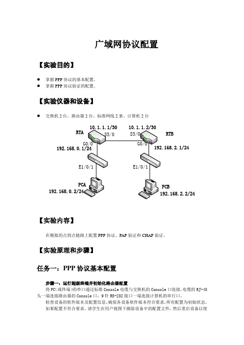
【实验仪器和设备】●交换机2台、路由器2台、标准网线2条、计算机2台RTBPCB【实验内容】在模拟的点到点链路上配置PPP协议、PAP验证和CHAP验证。
【实验原理和步骤】任务一:PPP协议基本配置步骤一:运行超级终端并初始化路由器配置将PC(或终端)的串口通过标准Console电缆与交换机的Console口连接。
电缆的RJ-45头一端连接路由器的Console口;9针RS-232接口一端连接计算机的串行口。
检查设备的软件版本及配置信息,确保各设备软件版本符合要求,所有配置为初始状态。
如果配置不符合要求,请学生在用户视图下擦除设备中的配置文件,然后重启设备以使系统采用缺省的配置参数进行初始化。
步骤二:依据规划建立两台路由器之间的物理连接将两台路由器的S1/0接口通过V35电缆连接,然后在RTA上执行命令display interfaceserial5/0,根据其输出信息可以看到:Serial5/0 current state: up Line protocol current state: upLink layer protocol is: ppp在RTB上执行同样的命令并查看如上信息,通过如上输出信息可以得知,路由器串口默认的链路层封装协议是ppp。
步骤三:配置路由器广域网接口IP地址在RTA上配置广域网接口S5/0的IP地址。
请补充完整的配置命令:[RTA]interface Serial 5/0[RTA-Serial5/0] ip address 10.1.1.1 30 在RTB上也完成广域网接口IP地址配置。
在RTA的S5/0接口模式下,执行命令display this,可以看到:interface Serial5/0link-protocol pppip address 10.1.1.1 32 ,根据此信息检查并核实配置的正确性。
广域网协议的封装
广域网协议的封装【实验名称】广域网协议的封装【实验目的】掌握广域网协议的封装类型和封装方法【背景描述】你是公司的网络管理员,两个分公司之间希望能够申请一条广域网专线进行连接。
公司现有锐捷路由器两台,希望你了解该设备的广域网接口所支持的协议,以确定选择哪一种广域网链路。
【技术原理】常见广域网专线技术有,DDN专线、PSTN/ISDN专线、帧中继专线、X.25专线等。
数据链路层提供各种专线技术的协议,主要有PPP、HDLC、X.25、Frame-relay以及ATM等。
【实现功能】查看路由器广域网接口支持的数据链路层协议,并进行正确的封装。
【实验设备】R1762路由器(1台)【实验拓扑】【实验步骤】步骤一查看广域网接口默认的封装类型:Router1# show interface serial 1/2serial 1/2 is UP , line protocol is UP //查看接口的状态,是否为UP Hardware is PQ2 SCC HDLC CONTROLLER serialInterface address is: 1.1.1.2/24 //查看接口IP地址的配置MTU 1500 bytes, BW 512 Kbit //查看接口的带宽为512K Encapsulation protocol is HDLC, loopback not set//默认的封装协议是HDLC Keepalive interval is 10 sec , setCarrier delay is 2 secRXload is 1 ,Txload is 1Queueing strategy: WFQ5 minutes input rate 17 bits/sec, 0 packets/sec5 minutes output rate 17 bits/sec, 0 packets/sec511 packets input, 11242 bytes, 0 no bufferReceived 511 broadcasts, 0 runts, 0 giants0 input errors, 0 CRC, 0 frame, 0 overrun, 0 abort511 packets output, 11242 bytes, 0 underruns0 output errors, 0 collisions, 1 interface resets1 carrier transitionsV35 DTE cable //该接口为DTE 端DCD=up DSR=up DTR=up RTS=up CTS=up步骤二查看广域网接口支持的封装类型:RouterA(config)#interface serial 1/2RouterA(config-if)#encapsulation ?//encapsulation是封装数据链路层协议的命令frame-relay Frame Relay networks //帧中继协议hdlc serial HDLC synchronous //高级数据链路控制协议lapb LAPB(X.25 Level 2) //X.25的二层协议ppp Point-to-Point protocol //PPP点到点协议x25 X.25/ /X.25协议步骤三更改广域网接口的封装类型:PPP封装RouterA(config)#interface serial 1/2 //进行serial 1/2RouterA(config-if)#encapsulation ppp //将接口协议封装为PPP RouterA(config-if)#endRouterA#show interface serial 1/2 //查看接口的封装协议serial 1/2 is UP , line protocol is DOWNHardware is PQ2 SCC HDLC CONTROLLER serialInterface address is: 192.168.1.1/24MTU 1500 bytes, BW 2000 KbitEncapsulation protocol is PPP, loopback not setKeepalive interval is 10 sec , setCarrier delay is 2 secRXload is 1 ,Txload is 1LCP Reqsent //PPP协议相关参数Closed: ipcpQueueing strategy: FIFOOutput queue 0/40, 0 drops;Input queue 0/75, 0 drops5 minutes input rate 14 bits/sec, 0 packets/sec5 minutes output rate 36 bits/sec, 0 packets/sec403 packets input, 8866 bytes, 0 no bufferReceived 246 broadcasts, 0 runts, 0 giants15 input errors, 0 CRC, 15 frame, 0 overrun, 0 abort1011 packets output, 29156 bytes, 0 underruns0 output errors, 0 collisions, 59 interface resets1 carrier transitionsV35 DCE cableDCD=up DSR=up DTR=up RTS=up CTS=upFrame-Relay封装RouterA(config)#interface serial 1/2 //进行serial 1/2RouterA(config-if)#encapsulation frame-relay//将接口协议封装为帧中继RouterA(config-if)#endRouterA#show interface serial 1/2 //查看接口的封装协议serial 1/2 is UP , line protocol is UPHardware is PQ2 SCC HDLC CONTROLLER serialInterface address is: 192.168.1.1/24MTU 1500 bytes, BW 2000 KbitEncapsulation protocol is FRAME RELAY, loopback not set//封装协议Keepalive interval is 10 sec , setCarrier delay is 2 secRXload is 1 ,Txload is 1LMI enq sent 1, LMI status recvd 0, LMI update recvd 0, DTE LMI upLMI enq recvd 0, LMI status sent 0, LMI update sent 0LMI DLCI 0 LMI type is CCITT, frame relay DTE interface broadcasts 0//帧中继协议相关参数Queueing strategy: FIFOOutput queue 0/40, 0 drops;Input queue 0/75, 0 drops5 minutes input rate 15 bits/sec, 0 packets/sec5 minutes output rate 36 bits/sec, 0 packets/sec405 packets input, 8910 bytes, 0 no bufferReceived 246 broadcasts, 0 runts, 0 giants15 input errors, 0 CRC, 15 frame, 0 overrun, 0 abort1017 packets output, 29239 bytes, 0 underruns0 output errors, 0 collisions, 61 interface resets1 carrier transitionsV35 DCE cableDCD=up DSR=up DTR=up RTS=up CTS=upX.25封装RouterA(config)#interface serial 1/2 //进行serial 1/2 RouterA(config-if)#encapsulation X25 //将接口协议封装为X.25 RouterA(config-if)#endRouterA#show interface serial 1/2 //查看接口的封装协议serial 1/2 is UP , line protocol is DOWNHardware is PQ2 SCC HDLC CONTROLLER serialInterface address is: 192.168.1.1/24MTU 1500 bytes, BW 2000 KbitEncapsulation protocol is X.25, loopback not set //查看封装协议Keepalive interval is 0 sec , no setCarrier delay is 2 secRXload is 1 ,Txload is 1LAPB DTE, modulo 8, k 7, N1 12056, N2 20T1 3000, interface outage (partial T3) 0, T4 0State SABMSENT, VS 0, VR 0, Remote VR 0, Retransmissions 2Queues: U/S frames 0, I frames 0, unack. 0, reTx 0IFRAMEs 0/0 RNRs 0/0 REJs 0/0 SABM/Es 2/0 FRMRs 0/0 DISCs 0/0X25 DTE, address , state R1, modulo 8Defaults: DEF encapsulation, idle 0, nvc 3input/output window sizes 2/2, packet sizes 128/128 Timers: T20 180, T21 200, T22 180, T23 180, TH 0Channels: Incoming-only none, Two-way 1-1024, Outgoing-only noneRESTARTs 0/0 CALLs 0+0/0+0/0+0 DIAGs 0/0//X.25协议相关参数Queueing strategy: FIFOOutput queue 0/40, 0 drops;Input queue 0/75, 0 drops5 minutes input rate 16 bits/sec, 0 packets/sec5 minutes output rate 32 bits/sec, 0 packets/sec407 packets input, 8954 bytes, 0 no bufferReceived 246 broadcasts, 0 runts, 0 giants15 input errors, 0 CRC, 15 frame, 0 overrun, 0 abort1021 packets output, 29269 bytes, 0 underruns0 output errors, 0 collisions, 61 interface resets1 carrier transitionsV35 DCE cableDCD=up DSR=up DTR=up RTS=up CTS=up【注意事项】封装广域网协议时,要求V.35线缆的两个端口封装协议一致,否则无法建立链路。
DN06 广域网协议原理及配置
故障之一:链路始终不能转为Up状态
PPP验证参数配置不正确
故障之二:物理链路不能转为Up状态
show
interface serial number命令来查看接口状态
X.25协议概述
X.25
DTE DCE
X.25
公共网
DCE
X.25
DTE
X.25 协议是数据终端设备(DTE)和数据电路终接设备(DCE) 之间的接口规程。
encapsulation hdlc
设置存活时间以探寻链路及对端路由器的
工作状况
keepalive time
PPP协议简介
PSTN/ ISDN
接入服务器
PPP 封装
PPP协议是在SLIP的基础上发展起来的 PPP协议是数据链路层协议,位于第二层 物理层可以是同步电路或异步电路
PPP的组成
向分组层通知链路层的状态
X.25的配置
配置X.25工作模式
encapsulation x25 [[ dte|dce ] | [ bfe|cisco-compatible|ddn|ietf ]]
配置X.121地址
x25 address x.121-address
创建协议地址到X.121地址的映射
X.25的虚电路
统计时分复用
SVC(交换虚电路)和PVC(永久虚电路)
一个接口最多可以配置4095条虚电路
X.25的链路层协议LAPB
链路层的主要功能如下:
在DTE和DCE之间有效地传输数据 确保接收器和发送器之间信息的同步 检测和纠正传输中产生的差错
识别并向高层协议报告规程性错误
广域网实验
DTE
1.1.1.1/24
S1/2 Ra 被验证方
1.1.1.2/24
S1/2
Rb 验证方
பைடு நூலகம்
DCE
验证方: Rb(config)#username Ra password 0 star Rb(config)#interface seril 1/2 Rb(config-if)#encapsulation ppp Rb(config-if)#ppp authentication pap
3、验证测试
两台路由器互相ping,应该可以ping通。
4、想让认证被拒绝,应该怎么做?
验证方:
Ra(config)#username Rb password 0 star Ra(config)#interface serial 1/2 Ra(config-if)#encapsulation ppp Ra(config-if)#ppp authentication chap
3、验证测试
两台路由器互相ping,应该可以ping通。
4、想让认证被拒绝,应该怎么做?
实训内容
8.3 PPP CHAP认证
1.1.1.1/24
1.1.1.2/24
DTE
S1/2 Ra 验证方
S1/2 Rb
DCE
被验证方
1、基本配置(给两个接口配置IP地址等参数)
2、配置PPP CHAP认证
实训内容
8.2 PPP PAP认证
1.1.1.1/24
1.1.1.2/24
DTE
S1/2
Ra
被验证方
S1/2
1、基本配置(给两个接口配置IP地址等参数)
Rb 验证方
广域网协议封装与认证
广域网协议封装与认证【教学目标】1.知识目标:(1)理解PPP协议及其组成、帧结构。
(2)理解PPP会话建立的过程。
(3)理解PAP认证、CHAP认证及其特点。
(4)掌握PPP封装、PAP认证、CHAP认证的配置方法。
2.技能目标:(1)能够完成PPP协议封装的配置。
(2)能够完成PAP单向、双向认证的配置。
(3)能够完成CHAP单向、双向认证的配置。
3.素养目标(1)培养沟通交流及团队合作意识(2)养成规范操作的职业习惯(3)培养精益求精的工匠精神【教学重点】PAP单向、双向认证的配置。
【教学难点】CHAP单向、双向认证的配置。
【教学方法】项目教学法、启发式教学法、自主探究、合作探究。
【导入新课】企业组建局域网后都要接入广域网,在接入广域网过程中有多种数据链路层协议可以使用,但使用最广泛的是点对点协议(Point to Point Protocol,简称PPP),它不但能够将局域网接入广域网,而且还能够兼容不同厂商的设备,同时它还提供了两种认证方式,以确保数据传输过程中的安全性。
具体如何实现呢?我们一起来学习。
【教学过程】任务一:PPP协议拓扑结构:PPP协议拓扑结构如图10-1所示。
图10-1 PPP协议拓扑结构所需设备:路由器(型号1841)两台、V.35线一根。
规划IP地址:路由器RA端口s0/0/0的IP地址:192.168.0.1/24。
路由器RB端口s0/0/0的IP地址:192.168.0.2/24。
设备连线:路由器RA端口s0/0/0→路由器RB端口s0/0/0。
任务要求:在路由器RA和RB的s0/0/0端口上封装PPP协议。
知识点链接:4.封装PPP协议的配置路由器串行端口默认封装的是HDLC协议,如果要封装PPP协议,使用如下命令配置。
Router(config-if)#interface 串口Router(config-if)#encapsulation ppp配置时,需要在两个串口上都配置,另外,串行端口上除了可以封装PPP协议外,还可以封装高级数据链路控制协议(HDLC)、帧中继链路协议(Frame-relay)、封装X.25分组交换协议等。
- 1、下载文档前请自行甄别文档内容的完整性,平台不提供额外的编辑、内容补充、找答案等附加服务。
- 2、"仅部分预览"的文档,不可在线预览部分如存在完整性等问题,可反馈申请退款(可完整预览的文档不适用该条件!)。
- 3、如文档侵犯您的权益,请联系客服反馈,我们会尽快为您处理(人工客服工作时间:9:00-18:30)。
实验六 广域网协议封装与验证配置
一、实验目的
1.理解广域网协议的类型及工作原理。
2.掌握PPP 协议配置方法。
二、实验设备
路由器两台,PC 机两台,直连线两条,V35电缆两条。
三、实验步骤
1.按图6-1将实验设备连接好。
图6-1
2.为路由器Router1各接口封装PPP 协议及分配IP 地址。
Router1>enable
Router1#configure terminal
Router1(config)#interface fastethernet 1/0
Router1(config-if)#ip address 192.168.1.1 255.255.255.0 Router1(config-if)#no shutdown
Router1(config-if)#exit
Router1(config)#interface serial 1/2
Router1(config-if)#encapsulation ppp
Router1(config-if)#ip address 192.168.12.1 255.255.255.0 Router1(config-if)#clock rate 64000
Router1(config-if)#no shutdown
Router1(config-if)#end
Router1#show ip interface brief !显示路由器接口的配置 Router1#show interface serial 1/2
3.在路由器Router1上配置静态路由。
Router1# configure terminal
Router1(config)#ip route 192.168.2.0 255.255.255.0 192.168.12.2 Router1(config)#exit
Router1#show ip route !显示Router1上的静态路由信息
4. 为路由器Router2各接口封装PPP 协议及分配IP 地址。
Router2>enable
Router2#configure terminal
Router2(config)#interface fastethernet 1/0
Router2(config-if)#ip address 192.168.2.1 255.255.255.0
192.168.1.0/24 PC1 PC2
192.168.2.0/24 .1 .10 .1 .2 .1 .10 Router1 Router2 F 1/0 S 1/2 F1/0 S 1/2 DCE 192.168.12.0/24
Router2(config-if)#no shutdown
Router2(config-if)#exit
Router2(config)#interface serial 1/2
Router2(config-if)#ip address 192.168.12.2 255.255.255.0
Router2(config-if)#encapsulation ppp
Router2(config-if)#no shutdown
Router2(config-if)#end
Router2#show ip interface brief !显示路由器接口的配置
Router2#show interface serial 1/2
5.在路由器Router2上配置静态路由。
Router2# configure terminal
Router2(config)#ip route 192.168.1.0 255.255.255.0 192.168.12.1
Router2(config)#exit
Router2#show ip route !显示Router2上的静态路由信息
6.配置PC1和PC2。
将PC1的IP地址设为192.168.1.10,子网掩码设为255.255.255.0,网关设为192.168.1.1。
将PC2的IP地址设为192.168.2.10,子网掩码设为255.255.255.0,网关设为192.168.2.1。
7. 测试网络的互连互通性。
C:\>ping 192.168.2.10 !从pc1 ping pc2
C:\>ping 192.168.1.10 !从pc2 ping pc1
如果两个方向都可以Ping通,那么,PPP协议配置成功!。