神港程序控制器PC-935说明书
FC系列中文操作说明(神港)
注意
• PID自整定(AT)的执行,请在试运行时实施。 • 为防止触电及发生调节仪故障,通电中请勿触及端子。 • 在实施端子锁紧或清洁作业时,必须在调节仪电源关闭的情况下执行。
通电期间作业,可能因触电而产生重大人身伤害。 • 在清洁时,请用柔软的干布。 • 应避免用硬物撞击和刮擦显示器。
1.2 模糊自整定 (1) 控制开始时,由以前的 PID 参数执行控制。 (2) 当控制结果因扰动或过程变化而异常时,仪表则监测此时的收敛状态,如有必要,自动调整 PID 参数。 (a)如收敛平滑且速度不慢,不改变 PID 值。 (b)如收敛速度太慢,仪表校正 PID 值使收敛变快。 (c)收敛过程中发现超调时,仪表自动调节 PID 值以避免发生超调。 (d)发生振荡时,调节仪检查波形和精细地自动调节 PID 值。 (3) 由内部开关设置,可使调节仪设定为带或不带模糊自行整定的 PID。
功能
1
控制方式
和
2
模糊自整定PID 控制 PID 控制 PD 控制 ON/OFF 控制
加热/冷却 3
加热(反作用)动作 冷却(正作用)动作
报警 1
无待机动作
待机
4
待机动作
报警 2
无待机动作
待机
5
待机动作
/
6
输入传感器
7*
K, J, R, B, N, PL- , Pt100, JPt100 S, E, T, C, 4 ~ 20mA, 0 ~ 20mA,
• 本调节仪使用说明书内所记载的注意及警告事项,请严格遵守。 如不遵守,可能导致重大伤害事故,请注意。
• 本说明书记载的内容可能会有变更。 • 本说明书尽可能予以周全叙述,如有不详或错误,敬请谅解,并予告知。 • 本调节仪计划安装在控制屏内,如果不是,请保证工作人员不能触摸到电源端子和高压部分。 • 不可将调节仪用于涉及人身安全的医学应用。 • 禁止任何未经授权的部分或全部复制本说明书。 • 本调节仪外壳是由阻燃树脂等做成的,请勿在易燃材料附近或易燃材料上安装本调节仪。
MIDI控制器说明

MIDI控制器(慢慢的摸索,这些足够大家用了吧)0 音色库选择MSB1号颤音:这个是我们常用的,它在合成器上有个轮,名字叫“Modulation”(调制轮)调制轮是可以分配的。
通常默认值分配给1号控制器,也就是颤音。
它是实时录音的,尽量不要修改。
觉得不满意最好从新录制,不然修改了比较不自然。
它的可取范围是0-127。
2号呼吸控制器:它是使用呼吸控制器直接输入的。
也就是说,它是实时录音所得到的。
有些时候您觉得不理想,可以修改它。
需要注意的是气口、起音、落音的自然。
它的作用是渐强、减弱、淡入、淡出的幅度。
听起来一定要有是真实的、人吹的感觉。
SAX等音色运用最多,其次是弦乐的独奏。
弦乐独奏一定要给人一个真正的演奏员在拉琴的感觉。
2号呼吸控制器的可取范围是0-127。
和7号音量控制器、11号表情控制器的作用相似,都是改变声音大小用的,但一般我们都用11号。
5号滑音时间:Portamento Time(滑音时间)这个控制器不单独使用。
它在单独使用时候没有效果,因为只有了滑音时间,而滑音的开关没有打开。
那么65号滑音控制器就可以算是一把钥匙。
也就是说65号的默认值是关闭状态,将它改为任意一个大于“0”的数字,“锁”就开了。
然后用5号设定滑音的时间,数值越大,滑音时间越长,反之则越小。
5号的可取范围是0-127,我们一般将它设置在20-30之间。
它和65号都是用鼠标输入的。
(“未曾初始化的piano演示”是运用滑轮作的,而“未加5&65控制器的sybass演示”是运用5&65控制器作的。
仔细研究吧~!)7号音量:它是控制Volume(音量)的一个控制器,这个控制器是我们在作MIDI时候必须使用的。
它是保证个声部音响平衡的关键。
它的可取范围是0-127。
我在初学MIDI时候,常常为了声音大,而把它调到127。
后来发现,后期缩混的时候很本没有上下调节的于地。
所以我建议将它的初始值设置成为80左右。
C10-4DM(English)日本神钢振动控制器说明书

■Please keep this “Instruction Manual” on file for further reference giving easy access
to the operator.
■The partsfeeder that is sold or rented to the other must keep this “Instruction Manual”
Warning
The electrical power supply to the Controller must be made through a customer-supplied safety disconnect switch mounted next to the Controller. Operate the Controller within the specified range in the contracted specifications, or it causes it malfunction, damage and/or shorter life time. Don’t get on and/or put a thing on the controller, or it results injury by fall, and/or damage and/or malfunction of it. Don’t bruise cords and/or leads. Bending by force, pulling, winding and/or clamping them cause fire and/or getting an electric shock by leakage and/or mal-conduction, and/or abnormal operation. Wire the Controller correctly consulting the “Instruction Manual”. Faulty wiring causes damage and/or abnormal operation of it. Before supply the Controller electrical power, check the wiring. The Controller must be grounded properly without fail. Don’t operate it without grounding.
JB-QT-5Li 型火灾报警控制器(联动型)使用说明书
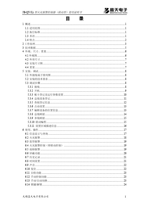
JB-QT-5Li 型火灾报警控制器(联动型)使用说明书目 录1.1 适用范围 ................................................................................................................................ 1 1.2 执行标准 ................................................................................................................................ 1 1.3 术语 ........................................................................................................................................ 1 1.4 特点 ........................................................................................................................................ 2 4.1外观图 ..................................................................................................................................... 6 4.2 外形尺寸 ................................................................................................................................ 7 4.3 安装尺寸图 ............................................................................................................................ 7 4.4 重量 ........................................................................................................................................ 7 5.1 外接线端子排列图 ................................................................................................................ 8 5.2 安装的技术要求 .................................................................................................................... 8 5.3 调试步骤 ................................................................................................................................ 8 5.3.1 接线 ................................................................................................................................. 8 5.3.2 开机 ................................................................................................................................. 9 5.3.3 板卡登记及运行参数设置 ........................................................................................... 10 5.3.4 总线设备登记 ............................................................................................................... 11 5.3.5 查阅登记信息 ............................................................................................................... 12 5.3.6 点动设置 ....................................................................................................................... 13 5.3.7 编辑设备的位置信息 ................................................................................................... 13 5.3.8 总线映射 ....................................................................................................................... 14 5.3.9 多线映射 ....................................................................................................................... 15 5.3.10 联动编程 ..................................................................................................................... 15 5.3.11 设置区域描述信息 ..................................................................................................... 16 6.1 信息显示与查询 .................................................................................................................. 17 6.2 火灾报警 .............................................................................................................................. 18 6.3 监管报警 .............................................................................................................................. 19 6.4 火灾报警控制(即联动控制) .......................................................................................... 19 6.5 故障报警 .............................................................................................................................. 19 6.6 屏蔽功能 .............................................................................................................................. 20 6.7 历史记录 .............................................................................................................................. 21 6.8 时间设置 .............................................................................................................................. 21 6.9 声音 ...................................................................................................................................... 22 6.10 复位 .................................................................................................................................... 22 6.11 自检功能 ............................................................................................................................ 23 6.12 手动控制功能 .................................................................................................................... 23 6.13 手动/自动切换 ................................................................................................................... 23 6.14 锁键/解锁 (24)1 概述............................................................................................................................................... 1 2工作原理 ........................................................................................................................................ 3 3 技术数据 ....................................................................................................................................... 5 4 外观、尺寸、重量 ....................................................................................................................... 6 5 安装、调试 ................................................................................................................................... 8 6 使用、操作 (17)JB-QT-5Li 型火灾报警控制器(联动型)使用说明书10.1 服务承诺 ............................................................................................................................ 26 10.2 质量保证 ............................................................................................................................ 26 10.3 联系方式 ............................................................................................................................ 26 7 故障分析与排除 ......................................................................................................................... 25 8 保养、维修 ................................................................................................................................. 26 9 开箱及检查 ................................................................................................................................. 26 10 其它 ........................................................................................................................................... 26 附录A 设备地址分配表 (27)JB-QT-5Li型火灾报警控制器(联动型)使用说明书您好!感谢您选用JB-QT-5Li型火灾报警控制器!这本使用说明书将引领您一步一步地了解这款机型的强大功能。
WJ(M-PRO)系列控制器使用说明书
Turck CoDeSys 3软件与程序可编程控制器应用指南说明书

Your Global Automation Partner Application Guide2 Turck Inc. | 3000 Campus Drive, Minneapolis, MN 55441 | T +1 763 553-7300 | F +1 763 509-7709 | Create a control system without a panelThe CoDeSys 3 (IEC 61131-3) software provides a powerful control environment supporting multiple common programming languages including ladder, structured text, function block diagram, and sequential function chart. This software can be downloaded for free at .A small button podium may be used to house items that must be enclosed in the panel.Turck programmable controllers provide up to IP68/IP69k protection, ideal for complete control of a system without the need for an enclosed control cabinet. These devices can function as a network master for remote I/O, additionally the flexible BL67 modular system allows for a variety of local I/O modules.3These devices can function as a network master or remoteI/O over multiple industrial fieldbus protocols including:*Indicates length in meters.BL67-PG-EN-V3TBEN-Lx-PLC-01■-40...+70 °C operating temperature ■IP67 Protection■Up to 32 local I/O modules(Discrete, analog, IO-Link, RFID, serial, etc.)■-40...+70 °C operating temperature ■IP68/IP69K Protection ■Onboard serial andconfigurable discrete I/O4 Turck Inc. | 3000 Campus Drive, Minneapolis, MN 55441 | T +1 763 553-7300 | F +1 763 509-7709 | Connect BL Ident RFID to any PLC5BL Ident Tags■Read/write times up to 2000 bytes/sec possiblewith FRAM Technology■Standard tags include 128 byteEEPROM and 2 kbyte FRAM tags■Available in high temperature packages, capable of up to 210 °C■Variety of tags available: bolts, ID-cards, adhesivelabels, autoclave, laundry, FDA approved■Data storage for 10 years at ambient temperatures■Flexible assembly lines: for custom build operations the required BOM could be stored into the tag and read out at each station ■Replace existing barcode system:barcode is reapplied due to paint or heat treatment where RFID can survivePLC6 Turck Inc. | 3000 Campus Drive, Minneapolis, MN 55441 | T +1 763 553-7300 | F +1 763 509-7709 | Connect fieldbus techology products to analog input devicesBL remote is a feature available on some gateway products. This feature allows bridging of device level networks to Ethernet. In this example, BL67 is operating on EtherNet/IP and drops down to the BL compact station using BL remote.Rod Style Series: ■Rugged rod style housing toallow operation in high shock and vibration environments ■Hydraulic cylinder applications where rod can withstand up to 5000 PSI continuously■Various analog output options ■16-bit resolution■Stroke length up to 168 inchesQ-track™ Series:■■ ■ ■ ■ ■Level Probe Series: ■Ideal for continuous level monitoring ■Uses magnetostrictive technologyto monitor float location■Analog output■Programmable monitoring span ■Stroke length up to 288 inches ■FM approved7Analog Sensors:■Pressure, temperature, sensors and transmittersfor use in pneumatic and hydraulic applications■Programmable digital read out flow sensors ■Highly reliable and precise temperature sensors ■Ultrasonic sensors■Linear analog sensors with wide range ofhousing styles and output options8 Turck Inc. | 3000 Campus Drive, Minneapolis, MN 55441 | T +1 763 553-7300 | F +1 763 509-7709 |BL67 I/O System can include digital, analog, IO-Link and RFID.2Parker Valve ManifoldsParker supplies a BL67 valve adapter base to directly connect Isys ISO and Micro valve banks to the Turck BL67 modular I/O system. Standard TurckBL67-16DO-0,1A-P output modules insert into the adapter base to provide direct control of up to 32 valve solenoids.Contact a local Parker distributor to order BL67 valve adapter and Parker valve banks.1Connect BL67 to valve banks with molded cables and discrete outputs, IO-Link, or direct connection9Possible Valve Bank Combinations■Channel-relatedshort-circuit monitoring■Wire-break detection■Configurable current monitoring ■Connection of multiple valve banksfrom different manufacturers■Integration of valve banks with digital output modules with 4, 8 or 16 channelsStandard and custom cordset lengthsThe 16-channel specially developed for switching valve banks. It features:10 Turck Inc. | 3000 Campus Drive, Minneapolis, MN 55441 | T +1 763 553-7300 | F +1 763 509-7709 | Hoist and hoist control systems for stage rigging systems move lights, sets and people using gear motors, brakes and winches.Amusement Machine groups product into case quantities and applies shrink film. Encoder tracks length of product ensuring the bar carrying film does not touch product.Packaging Encoder tracks rotations of a drum used to store cable.Cable ManagementVia SSIVia High Speed CounterConnect BL67 to rotary position sensorsAutomotive A shaft encoder is mounted to the drive rollers of a dynamometer to provide velocity feedback.11Features of QR24Rotary Position Sensors: ■Non-contact position measurement ■SSI communication interface ■Bus interface to CANopen ■Rugged IP68/IP69K rating■Highly resistant to noise interference ■Extremely fast (up to 12,000 RPM) andprecise (up to 29 bit resolution) ■Easy setup: IO-Linkparameterization via Pactware ■Available with analog andincremental outputsFeatures ofIncremental Encoders:■Optical technology■Solid and hollow shaft models ■Differential and single-endedmodes of operation■High noise immunity and precision ■Extremely fast (up to 12,000 RPM) ■Standard M12 and M23 connection12 Turck Inc. | 3000 Campus Drive, Minneapolis, MN 55441 | T +1 763 553-7300 | F +1 763 509-7709 | BL 67 I/O System■Rugged IP 67 construction allowsfor mounting directly on a machine without the use of an enclosure ■Modular design allows for variousI/O connections: up to 32 electronic modules, 256 digital or 64 analog■Support current and voltage I/O, RTDs, thermocouples, CAN Valve interface, RS232, RS422/485 and serial synchronous interfaces■Support of PROFIBUS, DeviceNet,CANopen, EtherNet/IP , Modbus TCP/IP , and PROFINET fieldbus■System diagnostic and per point diagnostic ■Fast and easy connectorization using7/8-16 UN Minifast ®, M12 Eurofast ®, M8 Picofast ® or M23 Multifast ® ■Configuration using free I/O-Assistantsoftware or rotary switchesEncoders BL ident (RFID)Sensors Solenoids Motor StartersTCP/IP13Possible CombinationsColor VisionBar Code VisionMachine Vision■Gray scale pattern and colorspectrum analysis■Two convenient form factors: one-piece PresencePLUS P4or compact PresencePLUS Pro sensor with a separate DIN-mountable controller ■Rugged IP 68-rated models suitablefor washdown applications* Indicates length in meters.Features of PresencePLUS ® Systems:■All PresencePLUS vision sensorsinclude built-in serial, EtherNet/IP and Modbus TCP/IP drivers with 4 (P4) or 6 (PROII) programmable I/O. A PresencePLUS sensor, with the Turck BL67 delivers expanded I/O, DeviceNet, PROFIBUS or PROFINET connectivity ■General-purpose or dedicated-function vision sensors■Discrete I/O on-board ■Wide range of mountingbrackets, lighting and lenses remote TEACH functionality to adjust image without PC ■Simple and intuitive userinterface with three-step, point-and-click operation■Rugged IP67 construction allows for mounting directly on a machine without the use of an enclosure ■Modular design allows for various I/O connections: up to 32 electronic modules, 256 digital or 64 analog ■Support current and voltage I/O, RTDs, thermocouples, CAN Valve interface, RS232, RS422/485 and serial synchronous interfaces ■System diagnostic andper point diagnostic■Fast and easy connectorization using7/8-16 UN Minifast®, M12 Eurofast®,M8 Picofast® or M23 Multifast®■Configuration using free I/O-Assistantsoftware or rotary switches■Support a wide variety offieldbuses including:»EtherNet/IP™»Modbus TCP/IP»PROFINET»DeviceNet™»PROFIBUS®-DP»CANopenBL67 I/O SystemInput/Output DevicesEncoders BL ident (RFID)Sensors SolenoidsConnect BL67 to wireless networkswith DX80 wireless gatewaysTCP/IP214 Turck Inc.|3000 Campus Drive, Minneapolis, MN 55441|T +1 763 553-7300|F +1 763 509-7709|15Possible Wireless Combinations* Indicates length in meters.Factory AutomationAgriculture and WaterTraffic ManagementCommercial andConsumer Monitoring16 Turck Inc. | 3000 Campus Drive, Minneapolis, MN 55441 | T +1 763 553-7300 | F +1 763 509-7709 | Stand alone I/O solutions powered by ARGEEWhen the door is closed the input sensor is on.No ARGEE actions take place in this condition.When the freezer door is open for more than 10seconds a warning light is turned on.With the freezer door open for more than 20seconds an audible alarm is turned on as well.When the door is closed at any time, the light and alarm are turned off and the timers are reset to zero.Door ClosedDoor OpenedDoor Opened for 20 Secs or MoreProgramming with an FLC (field logic controller) powered by ARGEE for a stand alone application could not be simpler. In the ARGEE Flow editor, a ladder like diagram editor, users use a drop down menu to select inputs, operations and outputs. When the program is running, the FLC carries out the program logic. Take the following stand alone freezer door application for example:17• This step in the program will monitor the door.• When the door is closed, our input value is on.• With this condition , we utilize the Boolean NOT operation to prevent Timer 1 and Timer 2 from starting.•With this logic, when the door opens, the action of starting Timer 1 and Timer 2 will begin.•When Timer 1 is expired, turn on Output 3 and illuminate our warning light.•When Timer 2 is expired, turn on Output 7 and sound our audible alarm.Slot 2. Input_value_0Time 1 ExpiredTime 2 ExpiredNOT Pass ThroughPass Through Pass Through Pass ThroughPass ThroughTON Timer 1No ActionSlot 2. Output_value_7TON Timer 2Slot 2. Output_value_3No ActionNo Action28 subsidiaries and over 60 representations worldwide!B3106 B 03/16©2016 by Turck Inc. All rights reserved. No part of the publication may be reproduced without written permission.Printed in USA。
定时程序控制器说明书2.0
定时程序控制器说明书2.0多维精控表格设置定时程序控制器说明书版本号2.0北京多维精控计算机技术开发中⼼版权信息北京多维精控计算机技术开发中⼼保留所有权利北京多维精控计算机技术开发中⼼保留在不事先通知的情况下,修改本⼿册中的产品和产品规格等⽂件的权利;不承担由于使⽤本⼿册或本产品不当,所造成直接的、间接的、附带的或相应产⽣的损失或责任;本产品及其软件具有专利权、版权及其它知识产权。
未经授权,不得直接或间接地复制、制造、加⼯本产品及其相关部分。
应⽤范围:本产品设计制造⽤于普通⼯业应⽤,超出预料的⽤途或对⼈的⽣命或财产造成重⼤影响的场合不在本产品应⽤和服务的范围。
表格设置定时程序控制器警告:必须将本表格设置定时程序控制器及其连接的电源和设备进⾏良好接地,否则可能会发⽣⼈⾝伤亡事故或设备故障!接地端⼦位置请参见图4所⽰。
应⽤范围:本产品设计制造⽤于普通⼯业应⽤,超出预料的⽤途或对⼈的⽣命或财产造成重⼤影响的场合不在本产品应⽤和服务的范围。
⼀、概述表格设置定时程序控制器(以下简称:控制器)是通⽤型程序控制器,⽆需编程,也不需要类似可编程控制器(PLC)那样设计梯形图,⽽是采⽤填表设置的⽅法代替繁琐的编程⼯作,操作使⽤⾮常⽅便,被称为:⽆需编程的“PLC”。
在实际应⽤中只要知道所控制设备的⼯作原理、需要达到的功能、如何让设备动作或运⾏,⽽进⾏简单的填表设置操作,即可快速实现所需的应⽤功能,达到程序控制设备或电器⾃动运⾏的⽬的。
控制器的前后分别设有两排接线端⼦,前⾯⼀排是输⼊端⼦,后⾯⼀排是输出端⼦,前排端⼦旁设有⼀个下载接⼝,⾯板上设有1个电源指⽰灯POW 、1个运⾏指⽰灯RUN、8个输⼊指⽰灯和8个输出指⽰灯,输⼊指⽰灯显⽰每个输⼊端的输⼊状态,输出指⽰灯分别显⽰每个输出端的状态,输出有效时指⽰灯亮。
定时程序控制器的应⽤功能是根据所需要的功能,在功能设置表上进⾏设置,设置完毕下载到控制器中,即可独⽴运⾏实现所设置的功能。
DCL说明书
(7) 窗口 说 明
窗口编号 内容 设 定值1(SV1)
1-1
说明
*此窗 口设 置第 一个 设定值 *设 置 范围 :传 感器 下限~传 感器 上限 *出厂 值为0
AT自整 定 2-1
*此 窗口设 置仪 表自 整定 功能 *当 处 于自 整定 期间,仪 表AT指示 灯闪 亮
*自 整 定结 束后,P,I, D,A RW参 数自 动 存 储
附: 在 高 低 温 控 制中,左边的DCL测试高 温区温度,右边的DCL测试低温区温度 再 温 湿 度 控 制 中,左边的DCL测试温度,右边的DCL 测试湿度
DCL: 左边
右边
通 信 协 议 :Modbus RTU协议 通信地址: 1
通 信 速 率 :9600bps 校验 选 择:Modbus RTU方式 停止位: 1
(5)D C L - 3 3 A操 作 流程图
按键
P V/ SV显 示
控制输出关闭功能 按 键1秒钟
输出 手动 操作 按 键3秒 钟
+
[主 设置 方式] 2-1[子设置 方式]
设 定 值1(SV1) AT自 整 定
+ 3秒
+隐藏 键 3秒
3
-1[辅助 设置方 式1]
设定之锁定功能
[辅传助感设器置选方择 式2 ]4
W(50A) C5
互 感 器 电 流 :50 A RS -485通 讯
(2) 输 入范 围(用 户在仪表 内自由选择)
输入类型
输入范围
K
- 2 0 0 ~ 1 3 7 0摄 氏 度
- 1 9 9 . 9~ 4 0 0. 0摄 氏 度
J
- 2 0 0 ~ 10 0 0摄 氏 度
神港JC系列通讯说明书
神港JC系列通讯说明书COMMUNICATION INSTRUCTION MANUALJCS, JCM, JCR, JCD-33A, C5No.JC3CE6 2005.04 To prevent accidents arising from the misuse of this controller, please ensure the operator receives this manual.WarningTurn the power supply to the instrument off before wiring or checking it.Working or touching the terminal with the power switched on may result in severe injury or death due to Electric Shock.1. System configurationRS-485 multi-drop connection communication (C5 option) (Fig. 1-1)(Fig. 1-2)Please use the IF-400 (sold separately) as a communication converter. 2. WiringWhen using communication converter IF-400 ? 9-pin Dsub connector: Connection: (Communication speed: 2400, 4800, 9600, 19200bps)Host computerConnection: (Communication speed: 2400, 4800, 9600, 19200bps)Shield wireConnect only one side of the shield wire to the FG terminal so that current cannot flow to the shield wire.(If both sides of the shield wire are connected to the FG terminal, the circuit will be closed between the shield wire and the ground. As a result, current will run through the shield wire and this may cause noise.)Be sure to ground the FG terminal. Terminator (Terminal resistor)Do not connect terminator with the communication line because each JC -33A has built-in pull-up and pull-down resistors instead of a terminator.-33AIt is necessary to set the instrument number individually to the JC -33A when communicating byconnecting plural units in serial communication (C5 option).Select a communication speed of the JC -33A in accordance with that of the host computer. ? For the instrument number setting and communication speed, refer to the instruction manual for JC -33A.4. Communication procedureCommunication starts with command transmission from the host computer (hereafter Master) and ends with the response of the JC -33A (hereafter Slave).Response with datathe master sends the reading command, the slaveresponds with the corresponding set value or current ?Acknowledgementthe master sends the setting command, the slaveresponds by sending the acknowledgement after theprocessing is terminated. ? Negative acknowledgement the master sends non-existent command or value out of the setting range, the slave returns the negative ? No responseaddress is set, or when there is a communication error(framing error or checksum error), or when LRC or CRCdiscrepancy is detected.Host computerCommunication timing of the RS-485 (C5 option)Slave sideWhen the slave starts transmission through RS-485 communication line, the slave is arranged so as to provide an idle status (mark status) transmission period of 1 or more characters before sending the response to ensure the synchronization on the receiving side.The slave is arranged so as to disconnect the transmitter from the communication line within a1 character transmission period after sending the response.Master side (Notice on programming)Set the program so that the master can disconnect the transmitter from the communication line withina 1 character transmission period after sending the command in preparation for reception of theresponse from the slave.To avoid the collision of transmissions between the master and the slave, send the next command after carefully checking that the master received the response.5. Shinko protocol5.1 Transmission modeShinko protocol is composed of ASCII codes.Hexadecimal (0 to 9, A to F), which is divided into high order (4-bit) and low order (4-bit) out of 8-bit binary data in command is transmitted as ASCII characters.Data format Start bit : 1 bitData bit : 7 bitsP arity : EvenS top bit : 1 bitError detection: Checksum5.2 Command configurationAll commands are composed of ASCII. The data (set value, decimal number) is represented withhexadecimal number, and ASCII code is used.The negative numbers are represented with 2's complement.(1) Setting command(2) Reading command(3) Response with data(5) Negative acknowledgementHeader: Control code to represent the beginning of the command or the response.ASCII codes are used.Setting command, Reading command : 02H fixedResponse with data, Acknowledgement : 06H fixedNegative acknowledgement : 15H fixed Number ofcharactersNumber ofcharactersNumber ofcharacters Number ofcharactersNumber ofcharactersAddress (Instrument number): Numbers by which the master discerns each slave. Instrument number 0 to 94 (00H to 5EH) and Global address 95 (7FH) The numbers (20H to 7EH) are used by giving 20H of bias, because 00H to 1FH are used for control code.95 (7FH) is called Global address , which is used when the same command is sent to all the slaves connected. However, the response is not returned.Sub address : 20H fixedCommand type : Code to discern Setting command (50H) and Reading command (20H) Data item : Data classification of the command object Composed of hexadecimal 4 digits (Refer to the Communication command table) Data : The contents of data (set value) depend on the setting command Composed of hexadecimal 4 digits (Refer to the Communication command table) Checksum : 2-character data to detect communication errors Delimiter : Control code to represent the end of command 03H fixed Error code : Represents an error type. Composed of hexadecimal 1 digit. 1 (31H)-----Non-existent command 2 (32H)-----Not used 3 (33H)-----Setting outside the setting range 4 (34H)-----Status unable to set (e.g. AT is performing) 5 (35H)-----During setting mode by keypad operation5.3 Checksum calculationChecksum is used to detect receiving errors in the command or data.Set the program for the master side as well to calculate the checksum of the response data from the slaves so that the communication errors can be checked. The ASCII code (hexadecimal) corresponding to the characters which range from the address to that before the checksum is converted to binary notation, and the total value is calculated.The lower 2-digit of the total value are converted to 2’s complements, and then to hexadecimal figures, that is, ASCII code for the checksum. Refer to the following example procedure. Checksum calculation example Main set value: 600 (0258H) Address (instrument number): 0 (20H)1’s complement: Reverse each binary bit. 0 will become 1 and vice ve rsa. ? 2’s complement: Add 1 to 1’s complements.20H50H0010 00000101 00001101 11111+[1's complement][2's complement][Hexadecimal][ASCII]5.4 Contents of the commandNotes on the setting command and reading commandPossible to set the set value by setting command of the communication function even when the set value is locked.Although the options are not applied, setting the items forthe options is possible by the setting command. However, they will not function.The memory can store up to 1,000,000 (one million) entries.If the number of settings exceeds the limit, the data will not be saved. So frequent transmission via communication is not recommended.When connecting plural slaves, the address (instrument number) must not be duplicated.When sending a command by Global address [95 (7FH)], the same command is sent to all the slaves connected. However, the response is not returned.The instrument number and communication speed of the slave cannot be set by communication function.Setting commandThe settable range is the same as that by key operation.For the communication command, refer to the communication command table of this manual. ? All commands are composed of ASCII.The data (set value, decimal) is converted to hexadecimal figures, and ASCII is used.A negative number is represented by 2's complement. When the data (set value) has a decimal point, a whole number without a decimal point is used. Reading commandAll commands are composed of ASCII.The data (set value, decimal) is converted to hexadecimal figures, and ASCII is used.A negative number is represented by 2's complement. When the data (set value) has a decimal point, the response is returned as a whole number without a decimal point.6. Modbus protocol6.1 Transmission modeThere are 2 transmission modes (ASCII and RTU) in Modbus protocol. 6.2 ASCII modeHexadecimal (0 to 9, A to F), which is divided into high order (4-bit) and low order (4-bit) out of 8-bit binary data in command is transmitted as ASCII characters. Data format Start bit : 1 bit Data bit : 7 bits P arity : Even/Odd/No parity (Selectable) S top bit : 1 bit/2 bits (Selectable) Error detection : LRC (Longitudinal Redundancy Check) Data interval : 1 second or less (1) Message configurationASCII mode message is configured to start by [: (colon)(3AH)] and end by [CR (carriage return) (0DH) + LF (Line feed)(0AH)]. (See Fig. 6.2-1)(2) Slave addressSlave address is an individual instrument number on the slave side and is set within the range 00H to 5FH (0 to 95).The master identifies slaves by the slave address of the requested message.The slave informs the master which slave is responding to the master by placing its own address in the response message.[Slave address 00H (broadcast address) can identify all the slaves. However slaves do not respond.] (3) Function code The function code is the command code for the slave to undertake the following action types (T able 6.2-1). (Table 6.2-1) Function code Contents 03 (03H) Reading the set value and information from slaves 06 (06H) Setting to slavesFunction code is used to discern whether the response is normal (acknowledgement) or if any error (negative acknowledgement) is occurred when the slave returns the response message to the master. When acknowledgement isreturned, the slave simply returns the original function code.When negative acknowledgement is returned, the MSB of the original function code is set as 1 for the response.Slave address FunctioncodeDataError check LRC Delimiter (CR)Header (:)Delimiter (LF)(For example, when the master sends request message setting 10H to function code by mistake, slave returns 90H by setting the MSB to 1, because the former is an illegal function.) For negative acknowledgement, exception code (Table 6.2-2) below is set to the data of response message and returned to the master in order to inform it that what kind of error has occurred. (Table 6.2-2)Exception code Contents1 (01H) Illegal function (Non-existent function)2 (02H) Illegal data address (Non-existent data address)3 (03H)Illegal data value (Value out of the setting range)17 (11H)Illegal setting (Unsettable status)18 (12H) Illegal setting (During setting mode by key operation, etc)(4) DataData depends on the function code.A request message from the master is composed of data item, number of data and setting data.A response message from the slave is composed of numberof bytes, data and exception codein negative acknowledgement. Effective range of data is –32768 to 32767 (8000H to 7FFFH).(5) Error check of ASCII modeAfter calculating LRC (Longitudinal Redundancy Check) from the slave address to the end of data, the calculated 8-bit data is converted to two ASCII characters and are appended to the end of message.Create a message in RTU mode.Add all the values from the slave address to the end of data. This is assumed as X.Make a complement for X (bit reverse). This is assumed as X.Add a value of 1 to X. This is assumed as X.Set X as an LRC to the end of the message.Convert the whole message to ASCII characters.Reading (Instrument number 1, SV)A request message from the masterThe number of data means the data item to be read, and it is fixed as (30H 30H 30H 31H).A response message from the slave in normal status (When SV=100)(Fig.6.2-3) The number of response bytes means the number of bytes of the data which has been read,and it is fixed as (30H 32H).A response message from the slave in exception (error) status (When data item is mistaken)The function code MSB is set to 1 for the response message in exception (error) status (83H).The exception code (02H: Non-existent data address) isreturned as contents of error.Setting (Instrument number 1, SV=100)A request message from the master(Fig.6.2-5)A response message from the slave in normal status(Fig.6.2-6)SlaveaddressFunctioncodeData itemError checkLRCDelimiterHeader(30H 31H)Number ofdata(3AH)1224422(30H 33H)(30H 30H 30H 31H)(30H 30H 30H 31H)(46H 41H)(0DH 0AH)Number of charactersSlaveaddressFunctioncodeNumber ofresponse bytesError checkLRCDelimiterHeader Data1222422(3AH)(30H 31H)(30H 33H)(30H 32H)(30H 30H 36H 34H)(39H 36H)(0DH 0AH)Number ofcharacters(0DH 0AH)SlaveaddressFunctioncodeExceptioncodeError checkLRCDelimiterHeader122222Number ofcharacters(3AH)(30H 31H)(38H 33H)(30H 32H)(37H 41H)SlaveaddressFunctioncodeData itemError checkLRCDelimiterHeader(30H 31H)Data(3AH)1224422Number ofcharacters(30H 36H)(30H 30H 30H 31H)(30H 30H 36H 34H)(39H 34H)(0DH 0AH)SlaveaddressFunctioncodeData itemError checkLRCDelimiter Header Data1224422Number ofcharacters (3AH)(30H 31H)(30H 36H)(30H 30H 30H 31H)(30H 30H 36H 34H)(39H 34H)(0DH 0AH)A response message from the slave in exception(error) status (When a value out of the setting range is set)(Fig. 6.2-7)The function code MSB is set to 1 for the response message in exception (error) status (86H). The exception code (03H: Value out of the setting range) is returned as contents of error.6.3 RTU mode8-bit binary data in command is transmitted as it is. Data format Start bit : 1 bit Data bit : 8 bits Parity : Even/Odd/No parity (Selectable) Stop bit : 1 bit/2 bits (Selectable) Error detection : CRC-16 (Cyclic Redundancy Check) Data interval : 3.5 characters transmission time or less (1) Message configurationRTU mode is configured to start after idle time is processed for more than 3.5 character transmission and end after idle time is processed for more than 3.5 character transmission. (See Fig.6.3-1) (Fig. 6.3-1) (2) Slave addressSlave address is an individual instrument number on the slave side and is set within the range 00H to 5FH (0 to 95).The master identifies slaves by the slave address of the requested message.The slave informs the master which slave is responding to the master by placing its own address in the response message.[Slave address 00H (broadcast address) can identify all the slaves. However slaves do not respond.] (3) Function code The function code is the command code for the slave to undertake the following action types (T able 6.3-1). (Table 6.3-1) Function code Contents 03 (03H) Reading the set value and information from slaves 06 (06H) Setting to slavesFunction code is used to discern whether the response is normal (acknowledgement) or if any error (negative acknowledgement) is occurred when the slave returns the response message to the master. When acknowledgement is returned, the slave simply returns the original function code.When negative acknowledgement is returned, the MSB of the original function code is set as 1 for the response.(For example, when the master sends request message setting 10H to function code by mistake, slave returns 90H bysetting the MSB to 1, because the former is an illegal function.) For negative acknowledgement, exception code (Table 6.3-2) below is set to the data of response message and returned to the master in order to inform it that what kind of error has occurred. (Table 6.3-2)Exception code Contents 1 (01H) Illegal function (Non-existent function) 2 (02H) Illegal data address (Non-existent data address) 3 (03H) Illegal data value (Value out of the setting range) 17 (11H) Illegal setting (Unsettable status) 18 (12H) Illegal setting (During setting mode by keypad operation, etc) (4) Data Data depends on the function code.A request message from the master side is composed of data item, number of data and setting data. A response message from the slave side is composed of number of bytes, data and exception code in negative acknowledgement. Effective range of data is –32768 to 32767 (8000H to 7FFFH). (5) Error check of RTU modeAfter calculating CRC-16 (Cyclic Redundancy Check) from the slave address to the end of data, the calculated 16-bit data is appended to the end of message in sequence from low order to high order.3.5 idle characters Slave address Function codeData Error check CRC 3.5 idlecharacters Slave addressFunction codeException codeError checkLRCDelimiterHeader2Number ofcharacters 22221(3AH)(30H 31H)(38H 36H)(30H 33H)(37H 36H)(0DH 0AH)How to calculate CRCIn the CRC system, the information is divided by the polynomial series. The remainder is added to the end of the information and transmitted. The generation of polynomial series is as follows.16 + X 15+ X 2 + 1)Initialize the CRC-16 data (assumed as X) (FFFFH).Calculate exclusive OR (XOR) with the 1st data and X. This is assumed as X.Shift X one bit to the right. This is assumed as X.When a carry is generated as a result of the shift, XOR is calculated by X ofand the fixeduntil shifting 8 times.up to the last data.Set X as CRC-16 to the end of message in sequence from low order to high order. RTU modeReading (Instrument number 1, SV) ? Request message from the masterThe number of data means the data item to be read, and it is fixed as 0001H. ? Response message from the slave in normal status (When SV=100)(Fig. 6.3-3)The number of response byte means number of bytes of the data which has been read, and it is fixed as 02H.Response message from the slave in exception (error) status (When non-existent data item is sent)The function code MSB is set to 1 for the response message in exception (error) status (83H). The exception code (02H: Non-existent data address) is returned as contents of error. Setting (Instrument number 1, SV=100) ? Request message from the masterResponse message from the slave in normal statusResponse message from the slave in exception (error) status (When a value out of the setting range is set)The function code MSB is set to 1 for the response message in exception (error) status (86H). The exception code (03H: Value out of the setting range) is returned as contents of error.3.5 idle charactersSlave address Function code Data itemError check CRC 3.5 idle characters(01H)(03H)(0001H)Number of data (0001H)(D5CAH)11222Number of characters3.5 idle charactersSlave address Function code Number of response bytesError check CRC 3.5 idle characters(01H)(03H)(02H)Data(0064H)(B9AFH)11122characters3.5 idle charactersSlave address Function code Exception code Error check CRC 3.5 idle characters(01H)(83H)(02H)(C0F1H)1112Number of characters3.5 idle charactersSlave address Function code Data item Error check CRC 3.5 idle characters(01H)(06H)(0001H)Data (0064H)(D9E1H)11222characters 3.5 idle charactersSlave address Function code Data item Error check CRC 3.5 idle characters(01H)(06H)(0001H)Data(0064H)(D9E1H)112223.5 idle characters Slave address Function code Exception code Error check CRC 3.5 idle characters(01H)(86H)(03H)(0261H)1112characters7. Communication command tableWhen the data (set value) has a decimal point, remove the decimal point and represent it as a whole number, then express it in hexadecimal figures.Shinko command type ModbusfunctioncodeData item Data20H/50H 03H/06H 0001H: SV1 Set value20H/50H 03H/06H 0002H: Not used20H/50H 03H/06H 0003H: AT/Auto-reset setting 0000H: Cancel 0001H: Perform 20H/50H 03H/06H 0004H: OUT1 proportional band setting Set value20H/50H 03H/06H 0005H: OUT2 proportional band setting Set value20H/50H 03H/06H 0006H: Integral time setting Set value20H/50H 03H/06H 0007H: Derivative time setting Set value 20H/50H 03H/06H 0008H: OUT1 proportional cycle setting Set value20H/50H 03H/06H 0009H: OUT2 proportional cycle setting Set value20H/50H 03H/06H 000AH: Not used20H/50H 03H/06H 000BH: A1 setting Set value20H/50H 03H/06H 000CH: A2 setting Set value20H/50H 03H/06H 000DH: Not used20H/50H 03H/06H 000EH: Not used20H/50H 03H/06H 000FH: HB (Heater burnout alarm)settingSet value20H/50H 03H/06H 0010H: LA (Loop break alarm) timesettingSet value20H/50H 03H/06H 0011H: LA (Loop break alarm) spansettingSet value20H/50H 03H/06H 0012H: Set value lock selection (*1) 0000H: Unlock 0001H: Lock 10002H: Lock 2 0003H: Lock 3 20H/50H 03H/06H 0013H: SV high limit setting Set value20H/50H 03H/06H 0014H: SV low limit setting Set value20H/50H 03H/06H 0015H: Sensor correction value setting Set value20H/50H 03H/06H 0016H: Overlap/Dead band setting Set value20H/50H 03H/06H 0017H: Not used20H/50H 03H/06H 0018H: Scaling high limit setting Set value 20H/50H 03H/06H 0019H: Scaling low limit setting Set value 20H/50H 03H/06H 001AH: Decimal point place selection 0000H: XXXX (No decimal point)0001H: XXX.X (1 digit after decimalpoint)0002H: XX.XX (2 digits after decimalpoint)0003H: X.XXX (3 digits after decimalpoint)20H/50H 03H/06H 001BH: PV filter time constant setting Set value20H/50H 03H/06H 001CH: OUT1 high limit setting Set value 20H/50H 03H/06H 001DH: OUT1 low limit setting Set value 20H/50H 03H/06H 001EH: OUT1 ON/OFF actionhysteresis settingSet value20H/50H 03H/06H 001FH: OUT2 action mode selection 0000H: Air cooling0001H: Oil cooling0002H: Water cooling20H/50H 03H/06H 0020H: OUT2 high limit setting Set value 20H/50H 03H/06H 0021H: OUT2 low limit setting Set value 20H/50H 03H/06H 0022H: OUT2 ON/OFF action hysteresis settingSet value20H/50H 03H/06H 0023H: A1 action selection (*2)0024H: A2 action selection (*2) 0000H: No alarm action0001H: High limit alarm0002H: Low limit alarm0003H: High/Low limits alarm 0004H: High/Low limit range alarm 0005H: Process high alarm0006H: Process low alarm0007H: High limit alarm with standby 0008H: Low limit alarm with standby 0009H: H/L limits alarm w/standby[–200 to 1370400.0[–200 to 1000176017601820800400.013001390[0 to 2315[–199.9 to 850.0[–199.9 to 500.08505002500750.0[–320 to 1800320033001500750.023002500[0 to 4200[–199.9 to 999.9[–199.9 to 900.0[–300 to 15009004 to 20mA DC[–1999 to 9999]20H/50H 03H/06H 0048H: ARW (anti-reset windup) settingSet value20H/50H 03H/06H 006FH: Key Lock selection 0000H:Key enabled0001H: Key Lock50H 06H0070H:Key operation change flagclearing 0000H:No action 0001H: All clearing20H 03H 0080H: PV reading Present PV (input value)20H 03H 0081H: OUT1 MV reading Set value20H 03H 0082H: OUT2 MV reading Set value20H 03H 0083H: Not used20H 03H 0084H: Not used20H 03H 0085H: OUT status reading 0000 0000 0000 0000 215to 2020 digit: OUT10: OFF 1: ON21 digit: OUT20: OFF 1: ON22digit: A1 output0: OFF 1: ON23 digit: A2 output0: OFF 1: ON24 digit: Not used (Always 0)25 digit: Not used (Always 0)26 digit: HB (Heater burnout alarm)output0: OFF 1: ON(When sensor burnout, 0: OFF)27 digit: LA (Loop break alarm)output0: OFF 1: ON28 digit: Overscale0: OFF 1: ON29 digit: Underscale0: OFF 1: ON210 digit: OUT/OFF selection0: OUT 1: OFF211 digit: AT/Auto-reset0: OFF 1: ON212 digit: OUT/OFF key functions election0: OUT/OFF 1: Auto/Manual213 digit: Not used (Always 0)214 digit: Auto/Manual control0: Automatic 1: Manual215 digit: Change in key operation0: No 1: Yes20H 03H 0086H: Not used20H 03H 0087H: Not used20H 03H 00A0H: Not used20H 03H 00A1H: Instrument information reading 0000 0000 0000 0000215to 2020 digit: Not used (Always 0)21 digit: Cooling action0: Not applied 1: Applied22 digit: A1 function0: Not applied 1: Applied23 digit: A2 function0: Not applied 1: Applied24 digit: Not used (Always 0)25 digit: Not used (Always 0)26 digit: HB (Heater burnout alarm)0: Not applied 1: Applied27 digit: LA (Loop break alarm)0: Not applied 1: Applied28 to 215 digit: Not used (Always 0)This is why the set value reverts to the one before Lock 3 when power is turned OFF.(*2) When alarm action type is changed, the alarm set value reverts to the default value and alarm output status is also initialized.NoticeWhen data setting is changed by front keypad operation, the data that is related to the changed item is also changed automatically as shown in Example 1 below.However, when the data setting is changed by communication function, the related data does not change as shown in Example 2 below. (Only the changed data is altered.) (Example 1) SV high limit: 1370SV: 1000When SV high limit is changed to 800 by the front keypad operation, both SV high limit and SV are changed to 800.(Example 2) SV high limit: 1370SV: 1000When SV high limit is changed to 800 by communication function, SV high limit is changed to 800, however, SV ismaintained at the same temperature 1000.8. SpecificationsC able length : Maximum communication distance 1.2km Cable resistance: Within 50 (Terminator is not necessary or 120 or more on one side.)Communication line : EIA RS-485 Communication method : Half-duplexCommunication speed : 9600bps (2400, 4800, 9600, 19200bps) Selectable by keypad Synchronous system : Start-stop synchronous Code form : ASCII, binary Error correction : Command request repeat system Error detection : Parity check, Checksum (LRC), CRC Data format Start bit : 1 Data bit : 7, 8 Parity : Even, Odd, No parity Stop bit : 1, 29. TroubleshootingIf any malfunctions occur, refer to the following items after checking the power supply to the master and the slave.Problem: Communication failureCheck the followingThe connection or wiring of communication cable is not secure.Burnout or imperfect contact on the communication cable and the connector. Communication speed of the slave does not coincide with that of the master.The data bit, parity and stop bit of the master do not accord with those of the slave. The instrument number of the slave does not coincide with that of the command. The instrument numbers are duplicated in multiple slaves.Make sure that the program is appropriate for the transmission timing.Problem: Although communication is occurring, the response is 'NAK'.Check the followingCheck that a non-existent command code has not been sent.The setting command data exceeds the setting range of the slave.The controller cannot be set when functions such as AT are performing. The operation mode is under the front keypad operation setting mode.For further inquiries, please consult our agency or the shop where you purchased the unit.SHINKO TECHNOS CO.,LTD.OVERSEAS DIVISION::::Reg. Office Mail Address URL E-mail1-2-48, Ina, Minoo, Osaka, Japan P.O.Box 17, Minoo, Osaka, Japan http://www.shinko-technos.co.jp overseas@shinko-technos.co.jpTel :Fax:81-72-721-278181-72-724-1760。
神港温控表JC使用说明书
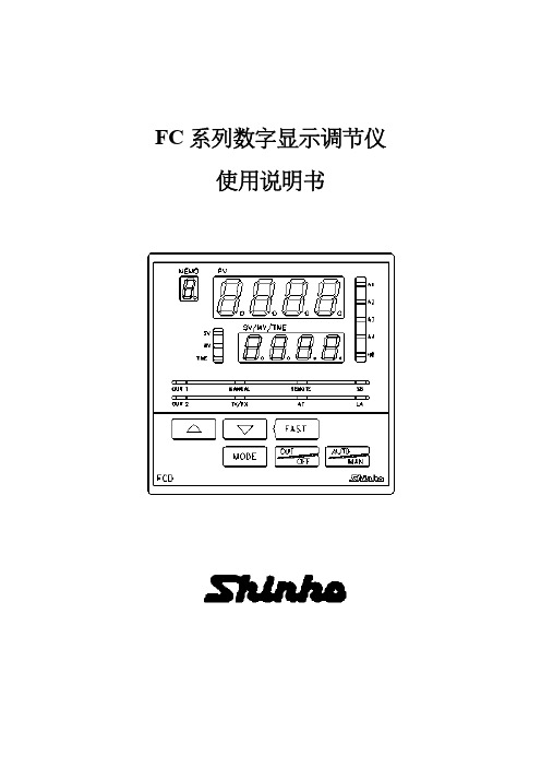
当控制输出功能停止时,PV 显示[OFF]。要打开控制输出功能,按开/关键 1 秒以上。
表 3.2-1 输入类型
℃
PV 显示
SV 显示
℉
PV 显示
SV 显示
K
K000
JF
1800
E Pt100
EC PT .C PT C
800 850.0 850
EF PT .F PT F
A
直流电流输入 DC 4~20 mA、0~20 mA
V
直流电压输入 DC 0~1 V、0~10 V
A2
报警输出 2
LA
回路异常报警
DR DS DA
控制输出(OUT2) 加热冷却控制
继电器触点 无触点电压 SSR 电流 DC 4~20 mA
特选功能
W(20) W(50)
加热断线报警
5A,10A,20 A 50 A
*2
绝对值下限报警
输入量程最小值~输入量程最大值℃(℉)
*2
上限报警加待机
-输入量程~输入量程℃(℉)
*1
下限报警加待机
-输入量程~输入量程℃(℉)
*1
上/下限报警加待机
-输入量程~输入量程℃(℉)
*1
·当输入有小数点时,最小值为-199.9,最大值为 999.9。
*1:对直流输入,输入量程为输入范围标定值。
量程 0~1370℃ 0~1000℃
0~800℃ -200~850℃ -199.9~850.0℃ -200~500℃ -199.9~500.0℃
0~2500℉ 0~1800℉ 0~1500℉ -300~1500℉ -199.9~999.9℉ -300~900℉ -199.9~900.0℉