P680A使用说明书
S8A 开环步进驱动器使用手册说明书

S8A开环步进驱动器使用手册OPEN-LOOP STEP MOTOR DRIVE User's Manual摩川技术(深圳)有限公司Moschon Technology(Shenzhen)Co.,Ltd.该产品由深圳市泰奇科智能技术有限公司独家发行,版权所有!目录前言/Foreword (3)1概述/Overview (3)1.1产品介绍/Product Introduction (4)1.2特性/Characteristics (4)1.3应用领域/Application areas (5)2性能指标/Performance Index (5)2.1电气特性/Electrical characteristics (5)2.2使用环境/Use environment (5)3安装/Installation (5)3.1安装尺寸/Mounting dimensions (5)3.2安装方法/Installation method (6)4驱动器端口与接线/Driver ports and wiring (7)4.1接线示意图/Schematic diagram of wiring (7)4.2端口定义/Port Definition (8)5拨码定义/Dial definition (13)5.1电流设定/Current setting (13)5.2细分设定/Subdivision setting (14)5.3功能设置/Function setting (14)5.4参数自整定功能/Parameter self-tuning function (125)6保修及售后服务/Warranty and after-sales service (16)前言/Foreword感谢您使用本公司开环步进驱动器。
Thank you for using our open step drive.在使用本产品前,请务必仔细阅读本手册,了解必要的安全信息、注意事项以及操作方法等。
戴尔 Vostro A840 A860 服务手册说明书
1
电池闩锁
2
3
电池
7. 按电源按钮以导去系统板上的残留电量。
电池槽释放闩锁
返回目录页面
返回目录页面
刷新 BIOS
Dell™ Vostro™ A840/A860 服务手册 请从 CD 刷新 BIOS 从硬盘驱动器快擦写 BIOS
如果新的系统板随附 BIOS 更新程序 CD,则请从该 CD 快擦写 BIOS。如果您没有 BIOS 更新程序 CD,则请从硬盘驱动器快擦写 BIOS。
返回目录页面
电池闩 锁部 件
Dell™ Vostro™ A840/A860 服务手册 卸下电池闩锁部件 装回电池闩锁部件
警 告 : 拆装计算 机内部组件 之 前 ,请 阅 读 计算 机 附带的 安 全说明 。 有关其它最佳安全操作信息,请参阅 /regulatory_compliance 上 的 Regulatory Compliance( 管 制标准 ) 主页。 注 意 :为避免静电损害,请使用接地腕带或不时地触摸计算机背面板上的连接器以确保接地,并导去身上的静电。
1. 确保工作台平整清洁,以防止刮伤主机盖。
2. 关闭计算机(请参阅关闭计算机)。 注 意 :要断开网络电缆的连接,请先从计算机上拔下网络电缆,再将其从网络设备中拔下。
3. 断开所有电话线或网络电缆与计算机的连接。
4. 合上显示屏,将计算机翻转过来,并放在平整的工作表面上。 5. 断开计算机和所有连接的设备与各自电源插座的连接。
卸 下币形电池
1. 请按照开始之前中的说明进行操作。 2. 卸下系统板(请参阅卸下系统板)。 3. 翻转系统板。 4. 从系统板连接器上断开币形电池电缆的连接。 5. 将币形电池从聚酯薄膜防护套中取出。
1
福禄克8060A四位半数字万用表中文说明书
2-5。物理特性................................................ ........2-6
2-6。前面板................................................ .......... 2-6
1-2。配套设备附件....................................................1 -4
1-3。规格................................................. ...........1-4
2。操作说明................................................ ..........2-1
5-6。校准和备用保险丝存取.............................................. 5-6
5-7。主PCB存取............................................... ......... 5-8
5-8。 LCD和PCB板微电脑解体和组装...................................... 5-9
5-18 。电流测试................................................ ........ 5-17
5-19 。二极管测试................................................ ...... 5-18
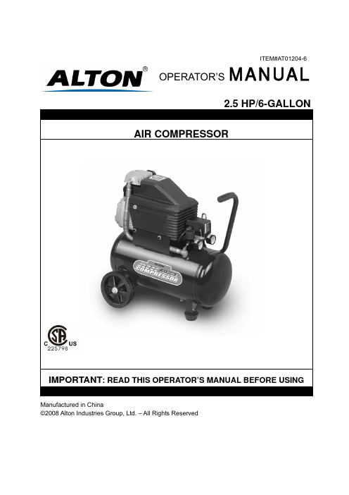
艾通2.5马力 6加仑空气压缩机使用说明书
Manufactured in China©2008 Alton Industries Group, Ltd. – All Rights ReservedOPERATOR’SMANUALITEM#AT01204-6-Page 2-This manual contains information that relates to PROTECTING YOUR SAFETY and PREVENTING EQUIPMENT PROBLEMS and is very important for you to know and understand. We use the symbols below to help you recognize this information.POTENTIAL HAZARD THAT WILL RESULT IN SERIOUS INJURY OR LOSS OF LIFEPOTENTIAL HAZARD THAT COULD RESULT IN SERIOUS INJURY OR LOSS OF LIFEPOTENTIAL HAZARD THAT MAY RESULT IN MODERATE INJURY OR DAMAGE TO EQUIPMENT1. RISK OF EXPLOSION OR FIRE.Never spray flammable liquids in a confined area. It is normal forthe motor and pressure switch to produce sparks while operating. If sparks come into contact with vapors from gasoline or other solvents, they may ignite and cause fire or explosion. Do not smoke while spraying. Do not spray where sparks or flame are present. Keep compressor as far from spray area as possible. Always operate the compressor in a well-ventilated area.2.RISK OF ELECTRIC SHOCK. A licensed electrician in accordance with all local and national codesmust install all wirings. To avoid electric shock, NEVER use an electric air compressor outdoors when it is raining or on a wet surface.3. RISK OF BURSTING. Rust can weaken the tank.Drain the condensed water from the tank aftereach use to reduce rusting. Welding or modifications on the air tank can severely impair tank strength and cause an extremely hazardous condition. So DO NOT weld, drill or modify the air tank of this compressor. If a leak is detected in the tank, replace the tank right away.4. RISK OF INJURY. ALWAYS shut off the compressor, remove the plug from the outlet and bleed allpressure from the system before servicing the compressor or when the compressor is not in use. Do NOT use the unit with the shrouds removed. Contact moving parts could cause serious injury.5. RISK OF BURSTING. Check the maximum pressure rating in the manual or the serial tag label.Compressor outlet pressure must be regulated so as to never exceed the maximum pressure rating. Relieve all pressure through the hose before removing or attaching accessories.6. RISK OF BURSTING. DO NOT adjust the pressure switch or relief valve for any reason. They havebeen preset at the factory for the maximum pressure of this unit. If the pressure switch or the relief valve are tampered with, personal injury or property damage may occur.7. RISK OF BURNS. Pump and manifold generate high temperature. To avoid burns or other injuries,DO NOT touch the pump, manifold or transfer tube while the unit is running. Allow the parts to cool before handling or servicing. Keep children away from the compressor at all times.8. RISK TO BREATHING. Be certain to read all labels when you are spraying paints or toxic materials,and follow the safety instructions. Use a respirator mask if there is a chance of inhaling anything you are spraying. Also, NEVER directly inhale the compressed air produced by a compressor.9. RISK OF EYE INJURY. ALWAYS wear ANSI Z87.1 approved safety goggles when using an aircompressor. NEVER point any nozzle or sprayer toward a person or any part of the body. If the spray penetrates the skin, serious injury may occur.1. Pull the pressure relief valve ring daily to ensure that the valve is functioning properly.2. The unit must be kept a minimum of 12 inches from the nearest wall, in a well-ventilated area forcooling.3. Protect the air hose and electric cord from damage and puncture. Inspect them weekly for weak orworn spots and replace if necessary.4. Always wear hearing pretection when using an air compressor. Failure to do so may result inhearing loss.5. Operation of the unit should always be in a position that is stable. Never use the unit on a rooftop orelevated position that could allow the unit to fall or be tipped over.-Page 3-B A CDEFGHIJK A--------ELECTRIC MOTOR B--------AIR COMPRESSOR PUMP C--------PRESSURE SWITCH D--------PRESSURE RELIEF VALVE E--------AIR PRESSURE REGULATOR F--------TANK PRESSURE GAUGE G--------REGULATED PRESSURE GAUGE H--------AIR LINE OUTLET I---------AIR TANK DRAIN VALVE J---------AIR TANK K--------POWER CORD-Page 4-A. ELECTRIC MOTOR: The motor is used to power the pump. It has a thermal overload protector and anautomatic reset. If the motor overheats for any reason, the thermal overload protector will shut it down to prevent the motor from being damaged. The motor will automatically restart when it completely cools.B. AIR COMPRESSOR PUMP: The pump is used to compress the air and discharge it into the tank viathe piston moving up and down in the cylinder.C. PRESSURE SWITCH: The switch is used to start or stop the air compressor. It is operated manually.When in ON position, it allows the motor to start when the air tank pressure is below the factory set cut-in pressure and allows the motor to stop when the air tank pressure reaches the factory set cut-out pressure. ALWAYS set this switch to OFF when the unit is not being used, and before unplugging the unit.D. PRESSURE RELIEF VALVE: The valve is used to prevent system failures by relieving pressure fromthe system when the pressure reaches the preset level while the pressure switch does not shut down the motor. It will pop open automatically or you can pull the ring on the valve to make it.E. AIR PRESSURE REGULATOR: The regulator is used to adjust line pressure to the tool you are using.Turn the knob clockwise to increase pressure and counterclockwise to decrease pressure.Never exceed the maximum working pressure of the tool.F. TANK PRESSURE GAUGE: The gauge is used to measure the pressure level of the air stored in thetank. It is not adjustable by the operator, and does not indicate line pressure.G. REGULATED PRESSURE GAUGE: The gauge is used to measure the regulated outlet pressure.H. AIR LINE OUTLET: The outlet is used to connect 1/4” NPT air hose.I. AIR TANK DRAIN VALVE: The drain valve is used to remove moisture from the air tank after the unit isshut off.Never attempt to open the drain valve when over 10 PSI of air pressure is in the tank.J. AIR TANK: The tank is used to store the compressed air.K. POWER CORD: This product is for use on a nominal 115 volt circuit and should be grounded. A cordwith a grounding plug, as K showed, shall be used. Make sure that the product is connected to an outlet having the same configuration as the plug (see Figure 1). No adapter should be used with this product.Check with a licensed electrician if the grounding instructions are not completely understood, or if in doubt as to whether the product is properly grounded. Do not modify the plug provided. If it will notfit the outlet, have the proper outlet installed by a licensed electrician.Improper installation of the grounding plug will resultis necessary, do not connect the grounding wire to either flat blade terminal. The grounding wire is in green outer surface.Figure 1Grounded outlet 115V/13 AGrounding Pin Plug -Page 5-1. Unpack the air compressor and inspect the unit fordamage and parts. If the unit has been damaged or some parts are missing, contact the agent immediately.2. Check the serial tag label to ensure that it has therequired pressure rating for its intended use.3. Take out two(2) wheels(A), two(2) bolts(B), four(4)washers(C), two(2) nuts(D) from the bag and install them on the foot section of the tank. (See Figure 2)4. Unpack the smaller plastic bag with the air filterincluded and have the air filter (A) assembled on the pump. (See Figure 3)5. Locate the compressor according to the followingguidelines:a. Set the compressor in a position near agrounded electrical outlet.b. The compressor must be at least 12 inchesaway from any wall or obstruction, in a clean,well-ventilated area, to ensure sufficient airflow and cooling.c. The compressor must be level to ensureproper drainage of the moisture in the tank.d. In cold weather, store the compressor in aheated building when not in use. This willreduce problems with motor starting andfreezing of water condensation.6. Connect an air hose with a 1/4” NPT fitting kit to thecompressor air line outlet. Figure 2DCAB-Page 6-Figure 3NOTE: The pump is shipped WITHOUT oil. Before starting, thebreak-in oil provided in an oil bottle should be poured in the pump through the oil nozzle. The break-in oil should be changed after 8 hours of operation. To reduce maintenance and repair problems, use only premium compressor oil. SAE 10W-30 all weather air compressor oil is recommended for general use.1. Check the oil level in the pump through the oil sight glass.The pump oil level must be between A1 and A2. Do not overfill or underfill. (See A)2. Turn the pressure switch to the OFF position (See B)3. Open the tank drain valve (See C). Turn in the counter-clockwise direction. 4. Plug in the power cord5. Turn the pressure switch to the ON position (See D). Theunit will start. Allow the unit to run for half an hour to break in the internal parts. After about half an hour, if the unit does not operate properly, shut down immediately and contact Product Service.6. After half an hour, turn the pressure switch to the OFF position.7. Close the tank drain valve. Turn in the clockwise direction.8. Turn the pressure switch to the ON position. The unit willstart and fill the tank to the cut-out pressure and stop.NOTE: The pressure switch will restart the motor automatically as compressed air is used. 1. Before starting, check the oil sight glass to ensure that oillevel in the pump is at the required level.2. Turn the pressure switch to the OFF position.3. Close the tank drain valve.4. Plug in the power cord.5. Turn the pressure switch to the ON position.6. Adjust the pressure regulator to the working pressure ofthe tool.When adjusting from a higher to a lower pressure, turn the knob counterclockwise past the desired setting, and then turn clockwise to reach the desired pressure. DO NOT exceed operating pressure of the tool or accessory being used. 1. Turn the pressure switch to the OFF position. 2. Unplug the power cord.3. Reduce pressure in the tank through the outlet hose. Youcan also pull the relief valve ring and keep it open to relieve pressure in the tank. (See E)Escaping air and moisture can propel debris that drain valve.CLOSEOPENEOFFONBCD-Page 7-Regular maintenance will ensure trouble free operation. The items listed in the chart should be inspected on a regular basis.ITEM DESCRIPTIONSERVICEINTERVALDrain the tank To prevent corrosion of the tank from the inside, the condensation must be drained at the end of every workday. Be sure to wear protective goggles. Relieve the air pressure in the system and open the drain valve on the bottom of the tank to drain.DailyCheck the oil Check the oil level in the pump through the oil sight glass. The pump oil level must be within the red circle. Do not overfill or underfill.DailyCheck the relief valve Pull the relief valve on the ring daily to ensure that it is operating properly and to clear the valve of any possible obstructions.DailyClean the air filter A dirty filter will reduce the unit’s performance and life.To avoid any contamination inside the pump, the filter should be cleaned frequently and replaced on a regular basis. Foam filter should be cleaned in warm and soapy water.WeeklyTest for leakage Check all connections to see if tight. A small leak in any of the tank, hoses, pipe connections or transfer tubes will absolutely reduce the unit’s performance.Spray a small amount of soapy water around the area of the suspected leak with a spray bottle. If bubbles appear, repair or replace the faulty component. Do not over tighten any connections.N/AStorage Before storing the unit for a long period, use an air blow gun to clean all dust and debris from the compressor. Disconnect and coil the power cord up. Clean the filter element and filter housing. Drain all moisture from the tank. Pull the pressure relief valve to release all pressure from the tank. Cover the entire unit to protect it from moisture and dust.N/A-Page 8-NOTE: Troubleshooting problems may have similar causes and solutions.PROBLEM POSSIBLE CAUSE SOLUTIONPower cord not plugged in Plug cord into grounded outlet Pressure Switch in “OFF”positionTurn switch to “ON” positionWrong gauge wire or length of extension cord Check chart on page 2 for proper gauge wire and cord length Motor thermal overload switch tripped Turn air compressor off, wait until motor is cool, then check motor circuit breakerFuse blown or circuit breakertripped-Replace fuse or reset circuit breaker -Check for proper fuse amperage-Check for low voltage conditions-Disconnect any other electrical appliances from circuit or operate compressor on its branch circuitAir tank pressure exceeds preset pressure switch limit Motor will start automatically when tank pressure drops below cut-in pressure of pressure tank. Check valve stuck openRemove and clean or replace Motor will not run or start Loose electrical connections Contact authorized service centerPossible defective motor, capacitor or check valveContact authorized service centerPressure switch does not shut off motor when air compressor reaches cut-out pressure and safety relief valve activatesMove the pressure switch to the OFF position. If the motor does not shut off, unplug the air compressor. If the electrical contacts are welded together, replace the pressure switch.Motor runs continuously when in the Start/Stop optionAir compressor not large enoughCheck air requirement of accessory used. If it is higher than CFM and pressure supplied bycompressor, a larger compressor is needed. Mostaccessories are rated at 25% of actual CFM while running continuously. Regulator does not regulate pressureDirty or damage regulator internal parts.Replace regulator.Fittings leakCheck fittings with soapy water. Tighten or reseal leaking fittings. But do not over tighten. Tank drain valve is open Close drain valveRestricted air intakeClean or replace air filter element. Prolonged excessive use of air Decrease amount of air used Hole in air hose Check and replace if necessaryTank leaksReplace unit immediately. DO NOT attempt to repair.Low pressure or not enough airValve leaksCheck and replace worn parts.Moisture in discharge airCondensation in air tank causedby high level of atmospherichumidity or air compressor did not run long enough.Drain air tank after each use. Drain air tank more often in humid weather and use an air line filter. Poor ventilationRelocate compressor to an area with cool, dry andwell-circulated air.Dirty cooling surfacesClean all cooling surfaces of pump and motorthoroughly.OverheatingLeaking valve Replace worn parts and reassemble with newseals.-Page 9-P/N DESCRIPTION QTY P/N DESCRIPTION QTYcover 11 Shroud 1 12Handle2 Wheel kit 2 13Pressure Switch 1fitting 13 Fan 1 14Adapter4 Capacitor 1 15Regulator 15 Air filter 1 16Pressure gauge 26 Pump/motor assembly 1 17Relief valve 1tank 1 7 Elbow 1 18Airkit 2 plug 1 19Pad8 Oilfill9 Transfer tube w/fins 1 20Drain valve 110 Bleeder tub 1 21Oil sight glass 111 Check valve 1 22Power cord 1-Page 10-。
P68 拆卸装配说明书

P68零配件目录拆卸及装配说明书●当订购配件时,请参见附表.1以及与此表对应的图.1。
●请标明零件号(参见图.1)、图号及所需零件数量。
●请标明型号、序列号、并根据减速机铭牌上注明的数据标出减速机的生产年份。
零配件订货示例:●When ordering spare parts,please refer to the table No.1and the figures No.1and No.2here of.●Specify the position(in accordance with the figure No.1),drawing number and the required quantity of spare parts.●Furthermore specify the type,serial number,year of production of gearbox according to data mentioned on the gearbox name plate.An example for ordering spare parts:附表1/Table No.1图.1/Figure No.1P68P68拆卸说明·卸下油堵41后,将油液全部倒出。
·用起重机将整个减速机放在操作台上。
型号:P68·旋松副轴壳体上的20个螺栓31。
·紧固两个挂环螺栓,用起重机将副轴壳体拆解。
·卸下中心轮12,取出轴承50。
·手动取下一级行星轮架3。
·在二级行星轮架5上紧固3个吊环螺栓M10,用起重机将二级行星轮架5架拆下。
·取下卡簧46,依次取下定位环21、22、23,在主壳体1前端旋紧两个挂环螺栓M10,通过起重机加压移动主壳体,然后在其下垫支撑物。
·给输出法兰加压,从主壳体上取下盖6。
·用起重机将主壳体移回操作台,并翻转过来放在较低的支撑物上。
LN6800

LN6800 智能停车管理系统
使用说明书
一、出入口控制机使用说明书 二、LPAB20、LPAB40 系列智能道闸
安装使用说明书 三、设计安装手册 四、软件使用说明书
拨码开关设置地址 5.1.2 DIP
................................................................................................................................................... 10
性能参数 2
................................................................................................................................................................................. 4
出口月卡车读卡 5.5
..................................................................................................................................................................... 22
http: //
3
厦门立林智能网络有限公司
LN6800 智能停车管理系统
1 说明
使用说明书
成都海霖科技有限公司微型泵专用调速器产品说明书

微型泵专用调速器产品说明书文档版本13发布日期2021-03-08版权所有©成都海霖科技有限公司2018。
保留一切权利。
非经本公司书面许可,任何单位和个人不得擅自摘抄、复制本文档内容的部分或全部,并不得以任何形式传播。
商标声明商标为成都海霖科技有限公司的商标。
本文档提及的其他所有商标或注册商标,由各自的所有人拥有。
注意您购买的产品、服务或特性等应受成都海霖科技有限公司相关合同和条款的约束,本文档中描述的全部或部分产品、服务或特性可能未包含在您的购买或使用范围之内。
除非合同另有约定,成都海霖科技有限公司对本文档内容不做任何明示或默示的声明或保证。
由于产品版本升级或其他原因,本文档内容会不定期进行更新。
除非另有约定,本文档仅作为使用指导,本文档中的所有陈述、信息和建议不构成任何明示或暗示的担保。
成都海霖科技有限公司地址:成都市双流区牧华路二段杰邦孵化谷邮编:610000网址:电话:************前言摘要本文为微型泵专用调速器系列产品的相关说明,用于指导相关技术人员初步了解该产品特性。
读者对象本文档适用于负责产品研发的技术人员,您应该非常了解您产品,并对所需微型泵的相关参数、规格大小等信息有明确概念。
关键字调速功能、开放式安装、触控显示器、报警功能修改记录修改记录累积了每次文档更新的说明。
最新版本的文档包含以前所有文档版本的更新内容。
目录前言 (I)修改记录 (II)目录 (III)1产品特性 (1)1.1.调速功能 (1)1.2.开放式安装 (1)1.3.防松螺母 (1)1.4.触控显示器 (1)1.5.保护功能 (2)1.6.报警功能 (2)1.7.数字信号控制 (2)1.8.转速闭环控制 (2)1.9.状态记忆功能 (2)1.10.型号说明 (3)2使用说明 (4)2.1.工作模式说明 (4)2.2.接线与操作说明 (4)2.3.告警与处理 (6)3安装说明 (7)3.1.多功能安装说明 (7)4注意事项 (9)5三维示意图 (10)6产品外观 (11)1产品特性1.1.调速功能与泵配套,可以实现对泵电机转速的调节,从而调节泵的输出流量。
P680A使用说明书

P680系列HPLC分析泵操作手册戴安中国有限公司技术服务中心2002.6目录1. 简介﹒﹒﹒﹒﹒﹒﹒﹒﹒﹒﹒﹒﹒﹒ 32.安装﹒﹒﹒﹒﹒﹒﹒﹒﹒﹒﹒﹒﹒﹒ 63. 操作﹒﹒﹒﹒﹒﹒﹒﹒﹒﹒﹒﹒﹒﹒234. 故障指南﹒﹒﹒﹒﹒﹒﹒﹒﹒﹒﹒﹒﹒﹒315. 维修﹒﹒﹒﹒﹒﹒﹒﹒﹒﹒﹒﹒﹒﹒331.简介P680系列HPLC分析泵有两种类型:高压梯度泵P680A HPG和四元低压梯度泵P680A LPG。
前者通过选装的溶剂选择器可以将二元梯度升级为四元梯度;P680A LPG具备在线脱气功能。
P680系列HPLC分析泵采用串联双泵头,电子压缩补偿方式。
流速范围是1μl/min~10ml/min,最高操作压力是50.0MPa(500bar)。
适用于标准和微孔HPLC。
P680可以进行面板操作,也可以借助CHROMELEON数据系统对其实施控制。
图1. P680前面板注意事项:1.为了保证P680的安全运行,必须设定高、低压极限;2.如果流动相中含有电解质成分,不能在没有清洗的情况下运行时间超过5分钟;3.缓冲溶液与有机溶剂转换时用去离子水清洗泵;4.如果P680停泵时间超过1小时,关掉检测器的光源;5.缓冲溶液的浓度不能高于1mol/L,pH范围1~13,Cl-的浓度小于0.1mol/L;2.安装2.1 安放P680系列HPLC分析泵的放置地点应满足以下要求:干燥、温度变化小、避免阳光直晒,实验台表面可以承受有机溶剂。
试剂瓶放在P680顶部的托盘上。
而P680可以放在ASI-100自动进样器的顶部。
图2. P680放置示意图2.2 更换保险丝(P/N 6030.9002)图3. 更换保险丝示意图2.3 后面板图4. P680后面板P680可以通过USB(Universal Serial Bus)或者LAN(Local Area Network)与安装Chromeleon工作站的计算机连接,RS232接口可以与ASI-100自动进样器或者STH585柱温箱连接。
- 1、下载文档前请自行甄别文档内容的完整性,平台不提供额外的编辑、内容补充、找答案等附加服务。
- 2、"仅部分预览"的文档,不可在线预览部分如存在完整性等问题,可反馈申请退款(可完整预览的文档不适用该条件!)。
- 3、如文档侵犯您的权益,请联系客服反馈,我们会尽快为您处理(人工客服工作时间:9:00-18:30)。
P680系列HPLC分析泵操作手册戴安中国有限公司技术服务中心2002.6目录1. 简介﹒﹒﹒﹒﹒﹒﹒﹒﹒﹒﹒﹒﹒﹒ 32.安装﹒﹒﹒﹒﹒﹒﹒﹒﹒﹒﹒﹒﹒﹒ 63. 操作﹒﹒﹒﹒﹒﹒﹒﹒﹒﹒﹒﹒﹒﹒234. 故障指南﹒﹒﹒﹒﹒﹒﹒﹒﹒﹒﹒﹒﹒﹒315. 维修﹒﹒﹒﹒﹒﹒﹒﹒﹒﹒﹒﹒﹒﹒331.简介P680系列HPLC分析泵有两种类型:高压梯度泵P680A HPG和四元低压梯度泵P680A LPG。
前者通过选装的溶剂选择器可以将二元梯度升级为四元梯度;P680A LPG具备在线脱气功能。
P680系列HPLC分析泵采用串联双泵头,电子压缩补偿方式。
流速范围是1μl/min~10ml/min,最高操作压力是50.0MPa(500bar)。
适用于标准和微孔HPLC。
P680可以进行面板操作,也可以借助CHROMELEON数据系统对其实施控制。
图1. P680前面板注意事项:1.为了保证P680的安全运行,必须设定高、低压极限;2.如果流动相中含有电解质成分,不能在没有清洗的情况下运行时间超过5分钟;3.缓冲溶液与有机溶剂转换时用去离子水清洗泵;4.如果P680停泵时间超过1小时,关掉检测器的光源;5.缓冲溶液的浓度不能高于1mol/L,pH范围1~13,Cl-的浓度小于0.1mol/L;2.安装2.1 安放P680系列HPLC分析泵的放置地点应满足以下要求:干燥、温度变化小、避免阳光直晒,实验台表面可以承受有机溶剂。
试剂瓶放在P680顶部的托盘上。
而P680可以放在ASI-100自动进样器的顶部。
图2. P680放置示意图2.2 更换保险丝(P/N 6030.9002)图3. 更换保险丝示意图2.3 后面板图4. P680后面板P680可以通过USB(Universal Serial Bus)或者LAN(Local Area Network)与安装Chromeleon工作站的计算机连接,RS232接口可以与ASI-100自动进样器或者STH585柱温箱连接。
2.4 流路连接P680的前面板可以向上翻起,便于用户操作。
注意:移动P680时,搬底部和侧面,不要损坏前面板。
图5. P680A流路连接图图6. P680A LPG流路连接图图7. P680A HPG/2流路连接图图8. P680A HPG/4流路连接图注意:使用有过滤头的管子连接溶剂瓶和P680;防止过滤头滋生细菌和微生物;不要使用锉刀截取不锈钢管。
请使用专用接头连接进样阀。
图9. 低压接头示意图图10. 高压接头示意图2.5 清洗柱塞使用高浓度的缓冲溶液时,为了防止盐分结晶、延长密封圈的寿命,P680安装了清洗后密封圈系统,可以连续清洗柱塞后密封圈。
此项功能可以在前面板的Options菜单中进行选择。
它由蠕动泵和内置传感器的溶剂瓶(100mL)组成,每一小时运行5分钟。
去离子水是最好的清洗液。
图11. P680A LPG清洗后密封圈系统流路连接图图12. P680A HPG清洗后密封圈系流路连接图蠕动泵的传送周期是5分钟,清洗液流回溶剂瓶时被安装在瓶口的传感器记录下来;如果5分钟后没有清洗液流回溶剂瓶,P680的屏幕将出现以下信息:Real-seal wash system has run out of wash solution.清洗液的管路出现破损或堵塞,溶剂瓶中没有清洗液,传感器被污染均会显示以上信息。
如果流回溶剂瓶的溶液超过规定值,P680的屏幕将出现以下信息:Possible piston seal leak detected.更换柱塞密封圈或者增加泄漏报警值均可消除以上信息。
注意;搬运P680之前应该倒空溶剂瓶中的清洗液。
每周更换一次溶剂瓶中的清洗液。
2.6 清洗泵图13. 清洗泵示意图在短时间内(5分钟)以高流速(6mL/min)清洗泵,修改此默认值可以在前面板的Options菜单中进行。
①中断P680与CHROMELEON的连接;②将一段软管插在压力传感器的废液出口,另一端与注射器连接;③拧松清洗阀,选择需要进行清洗的比例阀通道;④按Purge键,抽动注射器排出气泡,按Purge键停泵,拧紧清洗阀。
注意:比例阀通道必须逐一清洗;清洗阀只能在泵处于OFF状态时打开和关闭;清洗阀不能拧得太紧!按Purge键之前必须打开清洗阀门。
2.7 等浓度泵图14. P680A前视图2.8 低压梯度泵(LPG)图15. P680A LPG前视图图16. P680A LPG流路示意图注意:泵出口不能与真空腔连接;P680开机后,大约12分钟后达到最大真空度。
2.9 高压梯度泵(HPG)图17. P680A HPG/2前示图图18. P680A HPG/4前示图图19. P680A HPG流路示意图2.10 安装进样阀图20. 进样阀安装示意图注意:使用进样阀专用接头连接管路。
注射器的针头必须符合规定(参照进样阀说明书)。
3. 操作3.1 开机P680电源接通后,屏幕出现以下显示并执行自检程序,通过自检程序后进入主屏幕;如果出现错误信息,按Esc键进入主屏幕。
图21. 开机屏幕示意图用光标键选择主菜单中的指令或者进入下一级菜单,被选中的指令以下划线表示,按Enter键确认此项操作;按Esc键返回上一级菜单。
按Del键删除所选择的程序或光标所在行。
3.2 参数设定3.2.1 流速按Flow键后,按数字键输入,按Enter键确认。
3.2.2 混合比例按A/B/C/D键后,在压力显示窗口显示所选通道的混合比例。
按数字键输入,按Enter键确认。
注意:A、B、C、D四个通道混合比例的代数和必须是1。
3.2.3 压力极限按Max/Min键后,按数字键输入,按Enter键确认。
如果P680在运行时高于高压极限或者低于低压极限,停泵的同时,Off指示灯亮,A、B、C、D、MIN、MAX指示灯闪亮;P680和CHROMELEON的屏幕中也将出现相应的错误提示。
3.3 菜单操作图22. 主菜单在主菜单中用光标键选择State,按Enter键确认或按“1”均可进入状态菜单,输入流速、流动相组成和高、低压极限。
图23. 状态菜单图24. 程序菜单在主菜单中用光标键选择Programs,按Enter键确认或按“2”均可进入状态菜单,创建、删除、修改P680的运行程序。
按Del键可以删除光标所在行的步骤。
程序默认参数如下:编辑完成后按Esc键退出,根据以下屏幕提示选择存盘方式:如果创建新程序,依次按Save、Ins键,输入程序名称(字母或数字);3.3.1 自检菜单图25. 自检菜单在主菜单中用光标键选择Diagnostics,按Enter键确认或按“3”均可进入状态菜单,其中均为只读参数,不可更改。
3.3.2 配置菜单在主菜单中用光标键选择Programs,按Enter键确认或按“4”均可进入配置菜单。
图25. 配置菜单3.3.2.1 选项菜单在配置菜单中用光标键选择Options,按Enter键确认或按“2”均可进入选项菜单。
图26. 选项菜单3.3.2.2 硬件菜单在配置菜单中用光标键选择Options,按Enter键确认或按“3”均可进入硬件菜单。
其中均为只读参数,不可更改。
图27. 硬件菜单3.4 P680 HPG的注意事项如果通道A、C连接左侧泵头,通道B、D连接右侧泵头,P680HPG允许按照以下方式运行二元梯度:注意:同侧泵头的两个通道不能进行混合。
4. 自动控制4.1 P680在Chromeleon中的安装注意:先安装Chromeleon软件,再连接USB电缆。
①依次点击Start>Programs>Chromeleon>ServerMonitor,启动服务器后关闭该窗口;②打开Server Configuration,选中需要添加P680的timebase;③在Edit中点击Add Device,选择Dionex P680 Pump;屏幕显示P680的设置对话框,请用户根据仪器的实际情况进行修改和确认。
General TabHead Type & Limits Tab④存盘后退出Server Configuration。
5. 故障指南5.1 常见错误信息5.2 常见问题6. 维护6.1 注意事项①屏幕或键盘表面沾有溶液时,用软布吸去;②长期不用时,用甲醇清洗每个通道;③保修期间必须采用原厂包装箱运输仪器。
6.2 消除泄漏按Esc键消除屏幕上的泄漏提示,停泵,关断电源;检查泵头有无泄漏;擦干传感器和托盘,恢复操作。
如果没有擦干传感器就开泵,屏幕将出现以下提示:6.3 检查柱塞密封圈的泄漏①中断P680和 Chromeleon的联系;②在P680的Configuration菜单中选择“Rear SealWash=No”,再选择“Rear Seal Wash=Yes”,蠕动泵启动,输送2mL清洗液后停泵;③拆除清洗液瓶口传感器的硅胶管,将其中的液体排空后重新安装;④仔细观察硅胶管中的液面,如果没有变化图28. 清洗瓶示意图6.4更换单向阀①清洗泵,设置流速为零;②拆除单向阀连接管和单向阀;③更换单向阀芯(注意流向箭头),复原管路;④用甲醇以1.0mL/min的流速清洗泵头30min。
6.5 更换柱塞和密封圈图29. P680A HPG工作泵头示意图半制备泵图30. P680A 平衡泵头示意图半制备泵注意:由于柱塞密封圈为UHMW-PE材质,以下溶剂禁止使用:氯仿、三氯(代)苯、亚甲基氯、四氢呋喃、甲苯等。
注意:由于柱塞密封圈为UHMW-PE材质,会与以下溶剂发生化学反应,请慎重使用:四氯化碳、乙醚、异丙醚、酮、甲苯、甲基环己胺等6.5.1 拆卸泵头和柱塞①清洗泵,设置流速为零;②拆卸连接管路;③拧松固定泵头的两个内六角螺栓,向前抽出泵头;④拔出衬套,用随机提供的专用工具拧松定位螺丝,抽出柱塞。
6.5.2清洗柱塞①依次用家庭除垢剂和去离子水清洗卸下的柱塞,再用软布擦干;②在柱塞的金属部分涂上少量润滑脂。
6.5.3 拆除柱塞密封圈每个泵头中有两个密封圈,四个月更换一次。
6.5.4 更换柱塞、密封圈和泵头①插入柱塞, 用随机提供的专用工具拧紧定位螺丝;②按照正确的方向放入衬套;③按照正确的方向更换泵后密封圈(开口向外);④安装泵头衬套后, 更换泵前密封圈(开口向外);⑤将泵头复原,拧紧两个内六角螺栓;⑥重新安装进、出口单向阀并连接管路;⑦恢复操作前,用100%甲醇清洗30分钟(1.0ml/min)。
6.6 混合腔P680A LPG的延迟体积为390μL,P680A HPG的延迟体积为150μL。
流速低于0.1mL/min时应旁路混合腔。
图31. 混合腔示意图(P680A等浓度泵除外)图32. 混合腔与清洗阀示意图①清洗泵,关机,拔掉电源线;②分别拧松混合腔出口处与清洗阀入口连接管的接头;③拆除三个固定螺丝;④安装混合腔扩展段。