Westfalia油管0018-7944-000
滚珠丝杠(选型手册)

Westfalia分油机

Mineral Oil Separators Westfalia Separator etype
New Westfalia Separator unitrolplus system
The separators with new Westfalia Separator unitrolplus system are provided with two monitoring systems:
Water Monitoring System – WMS Sludge Monitoring System – SMS
Water Monitoring System (WMS)
The small volume of liquid (8) which is branched off via the separating disc (11) and the sensing liquid pump (9) is monitored by the WMS sensor (5). If the WMS sensor registers water, the solenoid valve (10) opens and the water flows off through the dirty water discharge (13). As soon as the WMS sensor detects a change brought about by an increased proportion of oil, the solenoid valve (10) closes and the solenoid valve (7) opens intermittently. The sensing liquid flow (8) is recycled into the feed (1).
Edwards XDS35i和XDS35i Enhanced滚动泵系列产品介绍说明书

XDS35i and XDS35i Enhanced FamilyThe XDS35i family of scroll pumps offer proven dry, clean vacuum solutions for a wide range of applications, with smart drive technology to look after the pump and provide world wide performance.Now, a combination of the patented double start scroll form technology and by-pass valves have enabledEdwards to offer the XDS35i Enhanced range of pumps to complement our original family. Take another step.With reduced peak power requirements at roughing pressures and continuous higher roughing speeds these enhanced pumps enable the user to take another step in terms of the performance envelope to address those special applications where roughing performance or the ability to evacuate a large volume is important.XDS35i and XDS35i Enhanced pumps are available as standard pumps with gas ballast, versions of the pump with no Gas Ballast (well suited for rare gas recirculation and gas recovery applications) and the C versions of the pumps featuring Chemraz® internal valves and stainless steel fittings for extra protection from the pumped media. XDS35i DRY SCROLL PUMPSBearing shieldensures separation between process gases and bearing lubrication to ensure clean vacuum and no possibility of contamination to lubrication from process gases, which prolongs bearing life.Smart motor drivemeans consistent performance globally, pump overload protection and remote start/stop capability.High flow gas ballast featureallows pumping of vapours including water vapour at up to 240 gh -1.Simple single sided scroll designallows maintenance to be done in minutes for low cost of ownership and maximum up-time.Take another stepthe Enhanced versions offer up to 20% lower peak powerrequirements during initial pump down which means it has the ability to pump down large volume chambers with no loss of performance and has up to 25% more pumping speed at these roughing pressures which helps on higher frequency cycling applications as well.Features and benefitsPRODUCT DATA SHEETSilencerVibration isolators (packof 4)EMEA UK +44 1444 253 000(local rate) 08459 212223Belgium +32 2 300 0730France +33 1 4121 1256Germany 0800 000 1456Italy + 39 02 48 4471Israel+ 972 8 681 0633ASIA PACIFIC China +86 400 111 9618India +91 20 4075 2222Japan +81 47 458 8836Korea +82 31 716 7070Singapore +65 6546 8408Taiwan +886 3758 1000AMERICAS USA +1 800 848 9800 Brazil+55 11 3952 5000 Publication Number: 3601 0458 01© Edwards Limited 2018. All rights reserved Edwards and the Edwards logo are trademarks of Edwards Limited.Whilst we make every effort to ensure that weaccurately describe our products and services, we give no guarantee as to the accuracy or completeness of any information provided in this datasheet.Edwards Ltd, registered in England and Wales No. 6124750, registered office: Innovation Drive,Burgess Hill, West Sussex, RH15 9TW, UK.GLOBAL CONTACTSA. NW40B. NW25BA333 (13.11)180 (7.09)130 (5.12)50 (1.97)476 (18.74)353 (13.90)212 (8.35)Ø187 (0.28)396 (15.59)223 (8.78)240 (9.45)304 (11.97)DimensionsPerformanceXDS35i0200400600800100012001400160018002000051015202530354045500.0010.010.11101001000P o w e r (W )P u m p i n g s p e e d (m 3/h r )Pressure (mbar)PUMPING SPEED AND POWERXDS35i speedXDS35i E speedXDS35i E powerXDS35i powerThe graph shows typical pump performanceNote that peak power for XDS35i is supplied for a short period of time before the intelligent drive reduces the power and speed XDS35i Enhanced, with its bypass valves, is not limited and will pump down continuously at full speed。
WSA分油机C7-623_控制板中文说明书

4.11 叫出模拟输入点 …………………………………
4.12 叫出模拟输出点 …………………………………
4.13 叫出提供服务地址 ………………………………
4.14 叫出分离机时间 …………………………………
4.15 叫出系统设定 ……………………………………
4.16 加载新的程序 ……………………………………
73
5.1.3 OSA / OSB 型分离机带“UNITROL”渣监察系统
(SMS)功能,供重燃用 …………………………
74
5.1.4 OSC 型分离机“– 02 –”设计 ……………………
76
5.1.5 OSC 型分离机“UNITROL”系统“WMS”功能 ..
79
5.1.6 OSC 型分离机“UNITROL”系统“SMS”功能 …
短路断流容量 ______ kA
电路图编号
_________________________
程序编号
_________________________
___________________________________________________________________________________________________ 8164-9001-400 / 0599
111
6.2.11 “SMS” – 没有超过最小分离时间(输入点 0.6)..
113
6.2.12 重燃油串联操作:选择上的错误 ……………….
115
6.2.13 排渣监测(模拟输出点 0.0) ……………………..
117
6.2.14 温度监测(仿真输出点 0.2) ……………………..
121
Westfalia轴承箱滑油0015-0003-080
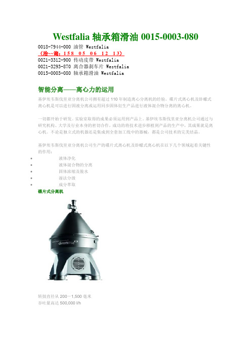
Westfalia轴承箱滑油0015-0003-080 0018-7944-000 油管 Westfalia(洽~~询:1 5 8 0 5 0 6 1 2 1 3)0021-3312-900 传动皮带 Westfalia0021-3293-870 离合器刹车片 Westfalia0015-0003-080 轴承箱滑油 Westfalia智能分离——离心力的运用基伊埃韦斯伐里亚分离机公司拥有超过110年制造离心分离机的经验。
碟片式离心机及卧螺式离心机是可以进行固液分离或运用同步固体衍生产品进行液体混合物分离的离心机。
一切都开始于研发。
实验室取得的成果必须运用到产品上。
基伊埃韦斯伐里亚分离机公司通过与研究机构、大学及行业本身的密切合作,成功的将技术进步移植到产品的生产中,其成果就是离心机。
不论是独立式的机器还是集成到全套加工线中的器械,都是公司技术的完美结晶。
基伊埃韦斯伐里亚分离机公司生产的碟片式离心机及卧螺式离心机在以下几个领域起着关键性的作用:∙液体净化∙液体混合物的分离∙固体浓缩及脱水∙湿法分级∙成分萃取碟片式分离机转鼓直径从200-1,500毫米吞吐量高达500,000 l/hTyco适配器接管 517.001.224BOWEN盘根 72355BOWEN冲洗管 83791英格索兰空滤39903281KIDDE消防软管站泡沫吸入管 SLP-6A-200 P/N:1233-1370-3 NWG轴承 3206C2a88001猫牌泵 3537卡特电瓶153-5710CIGWELD压力调节器 301563ORGA灯泡34B12285DYNALCO转速表 SPD-100TYCO探头 5BNOV 密封 648414308TYCO探头 5BEBRO ARMATUREN气动阀 EB5.1 SYDKOOMEY开关2200-0100罗斯蒙特变送器3051TG3A2B21AB4K5马丁电动机SVX18-7710DERRICK启动器,SQD-2510-MC03CR油封16119OTECO压力表361411OTECO压力表361511NUFLO 8寸流量计9A-100012094世伟洛克不锈钢管SS-T4-S-035-6ME世伟洛克不锈钢管SS-T4-S-049-6ME世伟洛克不锈钢管SS-T6-S-035-6ME世伟洛克不锈钢管SS-T6-S-049-6ME世伟洛克不锈钢管SS-T8-S-035-6ME世伟洛克不锈钢管SS-T8-S-049-6ME世伟洛克不锈钢管SS-T12-S-049-6ME世伟洛克不锈钢管SS-T12-S-065-6ME世伟洛克不锈钢管SS-T16-S-083-6ME世伟洛克SS-400-6世伟洛克SS-600-6世伟洛克SS-810-6世伟洛克SS-1210-6世伟洛克SS-1610-6世伟洛克SS-600-6-4世伟洛克SS-810-6-4世伟洛克SS-810-6-6世伟洛克SS-1210-6-4世伟洛克SS-1210-6-6世伟洛克SS-1210-6-8世伟洛克SS-1610-6-8世伟洛克SS-1610-6-12 世伟洛克SS-400-1-4世伟洛克SS-400-1-6世伟洛克SS-400-1-8世伟洛克SS-400-1-12世伟洛克SS-600-1-4世伟洛克SS-600-1-6世伟洛克SS-600-1-8世伟洛克SS-600-1-12世伟洛克SS-600-1-16世伟洛克SS-810-1-4世伟洛克SS-810-1-6世伟洛克SS-810-1-8世伟洛克SS-810-1-12世伟洛克SS-810-1-16世伟洛克SS-1210-1-6世伟洛克SS-1210-1-8世伟洛克SS-1210-1-12 世伟洛克SS-1210-1-16 世伟洛克SS-1610-1-8世伟洛克SS-1610-1-12 世伟洛克SS-1610-1-16 世伟洛克SS-400-6-4AN 世伟洛克SS-600-6-6AN 世伟洛克SS-810-6-8AN 世伟洛克SS-1210-6-12AN 世伟洛克SS-1610-6-16AN 世伟洛克堵帽SS-400-C 世伟洛克堵帽SS-600-C 世伟洛克堵帽SS-810-C 世伟洛克堵帽SS-1210-C 世伟洛克堵帽SS-1610-C 世伟洛克堵头SS-400-P 世伟洛克堵头SS-600-P 世伟洛克堵头SS-810-P 世伟洛克弯头SS-1210-P 世伟洛克堵头SS-1610-P 世伟洛克弯头SS-400-9 世伟洛克弯头SS-600-9 世伟洛克弯头SS-810-9 世伟洛克SS-1210-9世伟洛克弯头SS-1610-9 世伟洛克SS-400-3世伟洛克SS-600-3世伟洛克SS-810-3世伟洛克SS-1210-3世伟洛克SS-1610-3世伟洛克MS-PTS-6世伟洛克MS-PTS-50VAL-TEX配件P/N:VF-CTNVAL-TEX脚踏式注脂泵 QS-1800A-K VAL-TEX配件P/N:VF-CTNVal-tex密封脂80-H-J型派克溢流阀R25R25S1SN10 WLWALKER玻璃杯18962V15威格士电磁阀线圈300AA00086AK60N-064RDNGE 41B537963P1摩托罗拉适配器48180090-A2Val-tex密封脂80-H-J型VAL-TEX配件P/N:VF-CTNKERR设备器KM-111-0858-100 Alcad电池HB765P-1SEVERN TRENTDENOR灯泡62119 NOV伸缩缸销子M364001268NOV衬套30172475-28-24NOV开口销114320-7NOV销钉M364001238NOV胶管M361003094NOV弹簧M364001628NOV调节杆M364001627NOV弹簧皮碗M364001626NOV电缆M364001639NOV传感器M361004311-01NOV减压阀P854000093-HNOV电磁阀30175915-D2NOV传感器M361005514-01-050 NOV传感器M361005514-02-050 NOV塞绳M361005515NOV传感器84882-V2NOV传感器96388+30NOV阀94518-13HNNOV排出阀98005-13NOV活塞密封包108894-L32。
柴油机配件图示及中英文对照
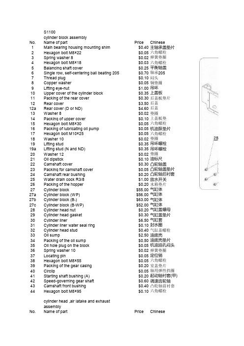
$0.20 气缸盖螺母 $0.30 气缸盖垫片 $6.50 气缸套 $0.10 封水圈 $0.40 气缸盖螺栓 $2.50 油底壳 $0.50 油底壳垫片 $0.05 机油油孔闷头 $0.02 弹簧垫圈 $0.05 定位销 $0.05 六角螺栓 $0.20 室盖垫片 $0.05 轴用弹性挡圈 $0.20 起动轴衬套(甲) $0.60 调速齿轮轴 $0.40 凸轮轴前衬套 $0.10 六角螺栓
$36.00 飞轮 $44.00 电启动飞轮
$0.05 曲轴平健 $1.20 曲轴正时齿轮 $0.05 轴用弹性挡圈30 $4.00 下平衡轴
Price Chinese $0.20 曲轴油封 $0.05 六角螺栓 $0.02 弹簧垫圈 $5.00 主轴承盖 $0.10 主轴承盖密封圈 $0.25 轴用弹性挡圈70 $8.00 轴承314 $0.50 轴承垫圈 $0.10 止退片
cylinder head ,air iatake and exhaust assembly No. Name of part
Price Chinese $0.40 主轴承盖垫片 $0.05 六角螺栓 $0.02 弹簧垫圈 $0.03 六角螺栓 $0.25 平衡轴盖 $0.70 轴承205 $0.10 闷头 $0.05 铜垫圈 $1.00 吊环 $0.35 上盖板 $0.30 后盖板垫片 $3.50 后盖 $4.60 后盖 $0.02 垫圈 $0.10 上盖板垫 $0.05 六角螺栓 $0.05 机油泵垫片 $0.05 六角螺栓 $0.02 垫圈 $0.35 吊环螺栓 $0.35 吊环螺栓 $0.02 垫圈 $0.10 油标尺 $0.30 凸轮轴盖 $0.05 凸轮轴盖垫片 $0.20 凸轮轴后衬套 $1.00 放水开关 $0.20 水箱垫片
Neil Pryde Sails Mainsail Lazy Bag MLB Installatio
I N T E R N A T I O N A L D E S I G N A N D T E C H N I C A L O F F I C E Lazy Bag Installation Guide© Neil Pryde Sails International1681 Barnum AvenueStratford, CONN. 06614Phone: 203-375-2626 • Fax: 203-376-2627Email: ************************Web: All material hereinCopyright 2006-2007 Neil Pryde Sails InternationalAll Rights ReservedOVERVIEWThe Neil Pryde Sails Mainsail Lazy Bag (MLB) is designed to be easily used and modular in design. It can conveniently be fitted and removed independently of the sail.•The MLB includes a zippered flap at the front of Array the bag that wraps around the mast to theopposite side of the bag and zippers closed. Thisis designed to reduce U.V. damage and keepbirds from nesting inside the mainsail!•The front flap can be left in place while sailing,or folded back inside the bag and secured with ahook & loop strip.•The top zipper is also provided with a flap tohelp decrease water ingress.•The MLB is attached to the boom usingslug/slides. The bag is NOT sewn between eachslide so that rain water AND reefing lines can beled from the sail through the bag to the boomattachment points.•Two adjustable webbing straps provide Fore/afttension; one strap is passed through the clew ringof the mainsail and the forward strap goesaround the mast (and inside the halyards). Thestraps are inside the bag to reduce U.V. exposure and allow the bag to be pulled aft over the sail, covering itcompletely. A third strap at the front/top can be used to tighten up the forward girth of the bag.•The battens are inserted from the forward end of the bag. The design is such, that the battens themselves become the attachment point for the lazy jacks. This reduces point loading and makes the bag smooth and taunt. Thebattens are locked in place with the internal Velcro closure system. (Identical to the mainsail batten pocketsystem)The following pictorial guide will outline the basic steps to installation.Installation ProcedureGetting Started:Assuming the sail is already in place, pull the entire sail to one side of the boom. This allows you to access the boom slot opening at the front of the boom, just behind the gooseneck.Starting with aft most end (short end) insert the furthest aft slug into the boom at the forward end of the boom just aft ofthe gooseneck and slide it aft. Add each succeeding slug until the cover is pulled aft completely. Both halves of the bag will be on the same side at this time. (Starboard in the photo)Pull one half of the bag underneath the sail and to theopposite side.The aft webbing strap is led through the clew ring of the sail and back into the buckle. The webbing should be pulled tight enough so that the bag covers the aft end of the sail. In the photo at right you can see the sail clew slug is pull out to the black band on the boom. The bag itself extends aft, past theblack band.With this preliminary adjustment made now insert each batten into the pocket. The ‘butterfly’ fitting is designed to seat with the webbing retainer. This means the unfinished batten end is inserted first. Make sure it is completely seated at the very aft end of the bag. At each opening along the sock mark the batten and remove the batten. We suggest that you make a 2” / 50mm wrap of white riggers tape at theselocations…as it will provide good friction and holding power for the lazy jack lines.Re-insert the battens. Pulling the bag tight and with a fair amount of tension on the battens, the battens should be just inside of the pocket fronts. If this is not the case, they are easily trimmed with a hacksaw.Now insert the webbing/Velcro strap folding the webbing over the butterfly end. This will lock the battens in place. This is the very same system as used on the mainsail battens and will require the ‘pusher stick’ that came with your mainsail for this operation.The jacklines are composed of three parts; the upper line that connects to the mast, the aft line that runs from the aft most connection point on the bag, to the upper ring and the forward line.Take your aft line and tie it around the rigging tape on the batten at the last most connection point on the bag. A double or triple clove hitch or fisherman’s bend are both very good knots that will resist slipping and be quite permanent.Tie the forward line in a similar fashion to the mid-attachment point on the bag.Take one turn on the forward line around the batten and pull the entire jackline system tight. The bag side should be pulled up smoothly and tightly.Later should you want, you can tie a overhand ‘shortening loop’ above the bag on the forward line and turn the rope end around the batten and back up to the loop, making a purchase system that can be secured with a couple of overhands.Do the opposite side in the same fashion.With both sides of the bag now pulled up and tight you need to check the fore/aft location of the bag. Do this by bringing the forward flap around the mast (inside the halyards) and zip it closed. If you cannot zip it or if it zips and is quite loose, the bag needs to be adjusted fore or aft depending on location.You will need to slide each slide backward or forward in small increments until the overall position is correct.Once achieved, readjust the webbing and the aft end and at the forward end take the lower strap around the mast (inside the halyards) and make it fast to the other side.The bag should be taut and smooth along the bottom as in photo at right.Both sets of reef lines can now be led down the inside of the bag and out the bottom and tied securely at the reef eye location.The forward upper webbing strap can now be fitted and is normally adjusted to be snug when the front flap is zipped closed. You can tighten it more to squeeze together the girth of the bag if you choose. This strap provides support should you choose to sail with the front flap tucked inside the bag.The aft eyelets can optionally be used to tidy up the trailingedge of the cover should you choose. Some like to tie a small line from the upper eyelets around the topping lift and back for an upward pull. In this photo we have utilized the eyelet on the rear of the boom to secure the lower eyelets. NOTE: In this picture you can clearly see that we havestretched the bag aft over the sail (which actually stops at the black band).Last Look:These final photographs illustrate the bag from a few vantage points.Forward starboard viewWith forward flap folded back inside and secured to the hookand loop strip.Forward line with shortening loop and hitch.Clove hitch at battenPortside view with front flap closed and zipped.Close up view looking aft.Top view looking forward。
Vestil FMDL 单 双肺鹰嘴叉叉搭载钢筋桩提升器说明书
Table of Contents Rev. 9/25/2023 FMDL MANUALSPECIFICATIONSA specifications document for your drum carrier model is available on the Vestil website: . Specifications include dimensions, net weight, and capacity information. To access the appropriate specifications document, navigate to the appropriate webpage: a) FMDL-1 and FMDL-2 = https:///product.php?FID=774; DFDL-3 = https:///product.php?FID=773; FPDL = https:///product.php?FID=772. Scroll the page to the “Product Specifications Table”. Click the button in the “PDFs” column that looks like a pencil inside a blue box. A PDF file will open. This file is the specifications document. Print a copy of the document and keep it with your copy of this manual. The following is an exemplar specifications document for model FMDL-1.SAFETY INSTRUCTIONSVestil strives to identify foreseeable hazards associated with the use of its products. Material handling is dangerous and no manual can address every conceivable risk. The end-user must exercise sound judgment at all times. Acquire a copy of the latest version of ANSI B56.1from . Apply all portions of Part II “For the User” that are relevant to front end attachments. The following recommendations complement the relevant provisions of B56.1.WARNINGUnsafe use of this product could result in serious personal injury or death.NOTE:Attach hook of ratchet strapQuick linkExploded View of 40-514-022NOTE 2:In order for the Eagle Beak™ mechanism to work properly,each drum and its contents must weigh AT LEAST 50 lb.(~22.7kg).Item Part No. Description Qty. Item Part No. Description Qty.1 40-514-008 Weldment, frame 1 13 40-612-004 Pin, clevis, 7/8” x 13/4” long,with washer22 40-112-001 Pin, main, clevis, 4 14 21-112-003 Pin, clevis, 1/2” x 13/4” long 43 40-514-022 Drum gripper assembly 2 15 40-016-053 Lower jaw, Eagle Beak™ 24 40-516-008 Weldment, bracket,mounting bar1 16 40-514-011 Weldment, pin bracket 25 65125 Cotter pin, zinc plated,3/16” x 11/2”4 17 40-014-054 Weldment, channel 26 99-112-004 Pin, self-locking quickrelease2 18 28-112-031 Pin, clevis, 3/4” x 41/4” 47 09-145-018 5/16” chain 56” long 1 19 40-612-006 Weldment, pin, cradleretainer28 40-145-008 Specialty hardware, snaphook, 5/16”1 20 40-014-093 Drum cradle 29 40-145-008 Strap with ratchet, 6’ long,2 hooks1 21 40-146-001 Spring, tension, 61/2” 210 28-112-031 Pin, clevis, 3/4” x 41/4” 2 22 37018 Lock nut, 1/4” - 20 411 45286 Clip, hitch pin, 1/8” x 25/8” 6 23 40-014-029 Frame, bar, formed 212 40-016-052 Upper jaw, Eagle Beak™ 2 24 11003 Bolt, hex head, 1/4” - 20 x3/4”4QuicklinkAttach hook of ratchetstrapFMDL-1 CENTER OF GRAVITY DIAGRAMS (40-007-006)FMDL-2 CENTER OF GRAVITY DIAGRAMS (40-007-004)Horizontal center of gravity (HCG): 237/8 inches (~60.6 cm) from the open ends of the fork pockets and 141/2” inches from the outermost edges of the fork pockets (dotted line in middle graphic above).Vertical center of gravity : 813/16 inches (~22.4 cm) from the top of the fork pockets.Horizontal center of gravity (HCG): 269/16 inches (~67.5 cm) from the open ends of the fork pockets and 205/8” (~52.4 cm) from the outermost edges of the drum lifter (dotted line in middle graphic above).Vertical center of gravity: 105/8 inches (~27.0 cm) from the top of the fork pockets.205/8” from outer edges141/4” from outer edgesFPDL-8-L CENTER OF GRAVITY DIAGRAMS (40-007-008)FPDL-11-H CENTER OF GRAVITY DIAGRAMS (40-007-007)Horizontal center of gravity (HCG):∙ 26 inches (~66.0cm) from the open ends of the fork pockets; and∙ 14¼ inches (~36.2cm) from the outer edge of each fork pocket (halfway between the forkpockets).Vertical center of gravity:∙ 51/2” inches (~14.0cm) from th e bottom of the fork pockets. Horizontal center of gravity (HCG):∙ 233/8 inches (~59.4cm) from the open ends of the fork pockets; and∙ 14¼ inches (~36.2cm) from the outer edge of each fork pocket (halfway between the fork pockets).Vertical center of gravity:∙ 97/16 inches (~24.0cm) from the bottom of the fork pockets.141/4” from outside edges of fork pockets141/4” from outside edges of fork pocketsHorizontal center of gravity (HCG):∙ 227/8 inches (~58.1cm) from the open ends of the fork pockets; and∙ 14¼ inches (~36.2cm) from the outer edge of each fork pocket (halfway between the fork pockets). Vertical center of gravity:∙ 10 inches (~25.4cm) from the bottom of the fork pockets.Horizontal center of gravity (HCG):∙ 231/8 inches (~58.7cm) from the open ends of the fork pockets; and∙ 14¼ inches (~36.2cm) from the outer edge of each fork pocket (halfway between the fork pockets). Vertical center of gravity:∙ 9 inches (~22.9cm) from the bottom of the fork pocketsHorizontal center of gravity (HCG):∙ 25½ inches (~64.8cm) from the open ends of the fork pockets; and∙ 13¼ inches (~33.7cm) from the outer edge of each fork pocket (halfway between the fork pockets). Vertical center of gravity:∙ 11 inches (~23cm) from the bottom of the fork pocketsDFDL EAGLE BEAK CENTER OF GRAVITY DIAGRAM (40-007-005)227/8”10”10”14¼”DFDL-3 LOWER DRUM GRIPPING ARMS CENTER OF GRAVITY DIAGRAM231/8”14¼”9”9”DFDL-3 UPPER DRUM GRIPPING ARMS CENTER OF GRAVITY DIAGRAM25½”97/8”97/8”13¼”USING THE LIFTERStep 1: Adjust the positions of the forks on the carriage (of your lift truck) to align with the fork pockets (of the lifter).Step 2: Mount the drum lifter on the forks of your lift truck by slowly driving forward until the forks contact the ends of the pockets.Step 3: Attach the safety chain to the fork carriage.Wrap the chain around the carriage. Fasten the snap hook to the chain or quick link (see exploded parts diagrams) without slack . The chain must not be able to disconnect from the carriage during use, i.e. slide off of the carriage.WARNING Unsafe use could result in death or serious injury.RECORD OF SATISFACTORY CONDITION (THE RECORD”)Before putting the drum lifter into service, record its condition. Thoroughly photograph the unit from multiple angles. Take close-range photographs of the drum gripping mechanism, the labels, all pivot points, the drum saddle(s), the safety chain and snap hook, and fork/tine locks (if applicable). Use the lifter to lift a drum. Describe how the drum grasping mechanism engages the drum. Describe all sounds produced by the lifter under load. Collate the photographs and writings into a file. Mark the file appropriately to identify it. Compare the results of all inspections to this record to determine whether the lifter is in satisfactory condition. Do not use the lifter unless it is in satisfactory condition. Purely cosmetic changes, like damaged paint or powdercoat are not changes from satisfactory condition. However, touchup paint should be applied to all affected areas as soon as the finish is damaged.NATIONAL STANDARDS section on p. 6,Vestil recommends that you acquire a copy of the most recent revision of this standard. Apply all use and maintenance/care instructions in the standard. Vestil also recommends that you contact your local occupational health and safety authority to determine if any state or local laws, regulations, codes, ordinances, etc. apply inspection requirements where the carrier is used.Inspections and all necessary repairs should be performed by qualified persons. Compare the results of each inspection to the RECORD OF SATISFACTORY CONDITION. Do not use the crane unless every part is in satisfactory condition. Purely cosmetic changes, like damaged paint/powdercoat, are not changes from satisfactory condition. However, touchup paint must be applied as soon as damage occurs to prevent rust from forming. Rust could cause the affected part to become unsound, which could make the carrier unsafe to use.D ON’T GUESS!If you have any questions about the condition of your product, contact the TECHNICAL SERVICE department.The phone number is provided on the cover page of this manual. Never make temporary repairs of damaged or missing parts. Only use manufacturer-approved replacement parts to restore the crane to satisfactory condition.INSPECTIONSA.Before each use inspect the following components:1.Carriage strap/chain and snap hook: Confirm that the latch of the snap hook automatically closes.Examine the strap for cuts, tears, and areas of significant wear. Examine the snap hook (at the free end of the strap). It must not be bent or cracked or twisted.bels: Labels must be easily readable, undamaged, and be located where indicated in theLABELING DIAGRAM on p. 9. If a label is damaged, unreadable, or missing, contact the TECHNICAL SERVICE AND REPLACEMENT PARTS DEPARTMENT to order a replacement.B.Periodic Inspections: At least once every 2 weeks inspect the carrier to confirm satisfactory condition. Do not return it to service unless it is in satisfactory condition.1.Fasteners (hardware) and hand chain: Examine all bolts, nuts, washers, pins, the quick link, and snaphooks. Tighten loose fasteners. Replace locking fasteners with new fasteners2. Fork pockets: Confirm that each pocket is structurally sound. In particular, examine the underside ofthe each pocket for rust and corrosion.3. Welds: Make sure that all welds are intact. Check welds & the metal surrounding welds for damage.4. Gripper arms and hinge castings: Confirm that both arms and hinge castings are not cracked orwarped. Hinge castings should rotate smoothly to allow the arms to fold onto the frame for compact storage.5. Safety strap, quick link, and hook (attached to the free end of the safety chain): Confirm that thequick link is undamaged and welded securely to the frame. The snap hook should not be bent, stretched, cracked, or otherwise damaged. Check the strap for cuts, tears, etc. If your unit is equipped with a safety chain instead of a strap, check the chain links for breaks, cracks, bends, elongations, etc.6. Pivot points/ hinges: Confirm that gripper arms pivot normally and/or that hinges operate normally.Check pivot points and hinges for significant wear. Lubricate the hinges. Lubrication might have to be applied more frequently under heavy usage conditions.7. Frame: The structure should be clean, square and rigid, and free of rust and corrosion. Clean theframe. Examine it for severe wear, rust, and other forms of damage.MAINTENANCEStep 1:Tag the unit “Out of Service.”Step 2: Remove any dirt or other matter from all surfaces.Step 3:Conduct a “Periodic” inspection. If deformity, corrosion, rusting, or excessive wear of structural members is found, permanently remove the unit from service.Step 4:Perform all necessary adjustments, replacements and/or repairs but DO NOT modify the carrier. DO NOT use the unit if adjustments and/or repairs are incomplete!An “adjustment” is a simple correction that restores the unit to satisfactory condition, such as tightening loose fasteners, or removing dirt or other debris from the surface. “Repair” refe rs to removing worn parts and installing manufacturer-approved replacement parts.A “modification” is a change that alters the drum carrier from satisfactory condition, like bending the structural members or removing a part or several parts. NEVER modify the unit without the express, written approval of Vestil. Modifications might make the device unsafe to use and automatically void the LIMITED WARRANTY.Step 5: Make a dated record of all repairs, adjustments and/or replacements.B : Label 218 (on fork pocket)BCC : Label 1153 (on fork pocket)AA : Label 485ADD : Label 1049 (on fork pocket)E : Label 1210 warning not to use with telehandlersEOPTIONAL EQUIPMENTCushioned drum cradles are available for FMDL-style drum lifters. Models FMDL-1-LDS-B1 and FMDL-2-LDS-B1 include saddles equipped with rubber belts. FMDL-1-LDS-R3 and FMDL-2-LDS-R3 provide rollers along the face of the drum saddle. Exploded views of cushioned models are provided on pages 15, 16, and 17.FMDL-1-LDS-B1 (40-006-101)Item*on p. 13) DRUM SADDLE ROLLER SUBASSEMBLYExploded Views on p. 15)FMDL-2-LDS-R3 (40-006-100)Item12345678*9* Roller subassemblyFMDL-1-LDS-B1 DIMENSIONS AND CENTERS OF GRAVITY (40-007-101)FMDL-2-LDS-B1 DIMENSIONS AND CENTERS OF GRAVITYHorizontal center of gravity (HCG): 2415/16 inches (~63.3cm) from the open ends of the fork pockets (middle graphic above) and 141/4” inches from the outermost edges of the fork pockets (dotted line in first graphic above).Vertical center of gravity: 81/2 inches (~21.6 cm) from the top of the fork pockets.NOTE:In order for the Eagle Beak™ mechanism to work properly, the drum and its contents must weigh AT LEAST 50 lb. (~22.7kg).141/4” from outer edgesHorizontal center of gravity (HCG): 291/16 inches (~73.8 cm) from the open ends of the fork pockets (middle graphic above) and 141/4” inches from the outermost edges of the fork pockets (dotted line in first graphic above).Vertical center of gravity: 101/8 inches (~25.7 cm) from the top of the fork pockets.NOTE:In order for the Eagle Beak™ mechanism to work properly, the drum and its contents must weigh AT LEAST 50 lb. (~22.7kg).141/4” from outer edgesNet weight: 295 lb. (134.1kg)Net weight: 304 lb. (138.2kg)FMDL-1-LDS-R3 DIMENSIONS AND CENTERS OF GRAVITY (40-007-099)FMDL-2-LDS-R3 DIMENSIONS AND CENTERS OF GRAVITY (40-007-100)Horizontal center of gravity (HCG): 253/16 inches (~64.0 cm) from the open ends of the fork pockets (middle graphic above) and 141/4” inches from the outermost edges of the fork pockets (dotted line in first graphic above).Vertical center of gravity: 81/2 inches (~21.4 cm) from the top of the fork pockets.NOTE:In order for the Eagle Beak™ mechanism to work properly, the drum and its contents must weigh AT LEAST 50 lb. (~22.7kg).141/4” from outer edgesHorizontal center of gravity (HCG): 281/8 inches (~71.4 cm) from the open ends of the fork pockets (middle graphic above) and 141/4” inches from the outermost edges of the fork pockets (dotted line in first graphic above).Vertical center of gravity: 915/16 inches (~25.2 cm) from the top of the fork pockets.NOTE:In order for the Eagle Beak™ mechanism to work properly, the drum and its contents must weigh AT LEAST 50 lb. (~22.7kg).141/4” from outer edgesNet weight: 304 lb. (138.2kg)Net weight: 206 lb. (93.6kg)LIMITED WARRANTYVestil Manufacturing Company (“Vestil”) warrants this product to be free of defects in material and workmanship during the warranty period. Our warranty obligation is to provide a replacement for a defective, original part covered by the warranty after we receive a proper request from the Warrantee (you) for warranty service.Who may request service?Only a warrantee may request service. You are a warrantee if you purchased the product from Vestil or from an authorized distributor AND Vestil has been fully paid.Definition of “original part”?An original part is a part used to make the product as shipped to the Warrantee.What is a “proper request”?A request for warranty service is proper if Vestil receives: 1) a photocopy of the Customer Invoice that displays the shipping date; AND 2) a written request for warranty service including your name and phone number. Send requests by one of the following methods:US Mail Fax EmailVestil Manufacturing Company (260) 665-1339 ***************2999 North Wayne Street, PO Box 507 Phone Enter “Warranty service request”Angola, IN 46703 (260) 665-7586 in the subject field.In the written request, list the parts believed to be defective and include the address where replacements should be delivered. After Vestil receives your request for warranty service, an authorized representative will contact you to determine whether your claim is covered by the warranty. Before providing warranty service, Vestil will require you to send the entire product, or just the defective part (or parts), to its facility in Angola, IN.What is covered under the warranty?The warranty covers defects in the following original, dynamic parts: motors, hydraulic pumps, motor controllers, and cylinders. It also covers defects in original parts that wear under normal usage conditions (“wearing parts”), such as bearings, hoses, wheels, seals, brushes, and batteries.How long is the warranty period?The warranty period for original dynamic components is 90 days. For wearing parts, the warranty period is 90 days. Both warranty periods begin on the date Vestil ships the product to the Warrantee. If the product was purchased from an authorized distributor, the periods begin when the distributor ships the product. Vestil may, at its sole discretion, extend a warranty period for products shipped from authorized distributors by up to 30 days to account for shipping time.If a defective part is covered by the warranty, what will Vestil do to correct the problem?Vestil will provide an appropriate replacement for any covered part. An authorized representative of Vestil will contact you to discuss your claim.What is not covered by the warranty?The Warrantee (you) is responsible for paying labor costs and freight costs to return the product to Vestil for warranty service.Events that automatically void this Limited Warranty.∙Misuse;∙Negligent assembly, installation, operation or repair;∙Installation/use in corrosive environments;∙Inadequate or improper maintenance;∙Damage sustained during shipping;∙Collisions or other accidents that damage the product;∙Unauthorized modifications: Do not modify the product IN ANY WAY without first receiving written authorization from Vestil.Do any other warranties apply to the product?Vestil Manufacturing Co.makes no other express warranties. All implied warranties are disclaimed to the extent allowed by law. Any implied warranty not disclaimed is limited in scope to the terms of this Limited Warranty. Vestil makes no warranty or representation that this product complies with any state or local design, performance, or safety code or standard. Noncompliance with any such code or standard is not a defect in material or workmanship.。
VFA Series Butterfly Valves Instruction Manual
VFA SeriesInstruction Manual D103670X012January 2015 - Rev. 00TMVFA Series Butterfly ValvesSummaryIntroduction ........................................................................ 1P .E.D. Categories and Fluid Group ................................... 1Characteristics ................................................................... 2Labelling ............................................................................ 2Overpressure Protection .................................................... 2Transport and Handling ..................................................... 2Atex Requirements ............................................................ 2Dimensions and Weights ................................................... 3Installation ......................................................................... 4Shutdown ........................................................................... 4Maintenance ...................................................................... 4Spare Parts ........................................................................ 5Parts Lists .......................................................................... 6Schematic Assemblies . (7)INTrODuCTION Scope of ManualThis manual provides instructions for installation, shutdown, maintenance and spare parts ordering for the VFA series butterfly valves.Product DescriptionThe butterfly valves series VFA are "wafer" flangeless type and are used typically in gas reducing stations for a on-off service.This series of butterfly valves is designed basically for trans-mission/distribution grids of the natural gas and for industrial/commercial applications.This product has been designed to be used with fuel gases of 1st and 2nd family according to EN 437, and with other non aggressive and non fuel gases. For any other gases, other than natural gas, please contact your local sales agent.Figure 1. Type VFA-MR Butterfly ValveThe following versions are available:VFa : Lever operated VFa-mr : Gear operatedVFa-mrO : Gear operated for use with absorbingodorizing systemsP .E.D. CaTEGOrIES aND FLuID GrOuPThis product is Pressure Equipment classified in the following categories in according to Directive 97/23/EC PED.Table 1. P.E.D. Categories And Fluid GroupTypeCaTEGOryFLuID GrOuPDN 50 PN 16 - ANSI 150I 1DN 65 ÷ 150 PN 16 - ANSI 150II DN 200 PN 16II DN 250 PN 16III DN 200 ÷ 250 ANSI 150IIIVFA Series2CharaCTErISTICSBody Sizes and End Connection StylesVFa • VFa-mr • VFa-mrODN 50 - 65 - 80 - 100 - 125 - 150 - 200 - 250PN 16 - ANSI 150 flangedThe pressure/temperature limits indicated in this instruction manual or any applicable standard or code limitation should not be exceeded.Maximum Operating Inlet PressurePN 16: 16 bar ANSI 150: 19 barAt average ambient temperature.Minimum/Maximum Allowable Temperature (TS)See labelTemperatureStandard Version:Working -10° to 60°CLow Temperature Version: Working -20° to 60°CMaterialsBody: Steel Disk: Pressed steel Shaft:Stainless steelGaskets: Nitrile NBR rubber (FKM on request)LabELLINGFigure 2. Label for VFA SeriesNote 1: See “Characteristics” Note 2: Year of manufacture Note 3: Temperature class -10°/60°C or -20°/60°C Note 4: PN 16 PS: 16 bar ANSI 150 PS: 19.3 barThe Category I pressure equipments will not have on label any Notified Body reference.OVErPrESSurE PrOTECTIONThe recommended safety pressure limitations are stamped on the valve nameplate (PS). Some type of overpressure protec-tion is needed if the actual inlet pressure exceeds this limits.Personal injury, equipment damage, or leakage due to es-caping fluid or bursting of pressure-containing parts may re-sult if this relief valve is over-pressured or is installed where service conditions could exceed the design operative limits.Valves operation below the maximum pressure limitations does not preclude the possibility of damage from external sources or debris in the line.The valves should be inspected for damage after any over-pressure condition..TraNSPOrT aND haNDLINGEstablished transport and handling procedures shall be fol -lowed to avoid any damage on the pressure containing parts (valve body) by shocks or anomalous stresses.In case of necessity of a harness, a nylon harness will have to be used in order to protect the surface and possible valve accessories.aTEX rEquIrEmENTSIf the provisions of EN 12186 & EN 12279, national regulations, if any, and specific manufacturer recommendations are not put into practice before installation and if purge by inert gas is not carried out before equip -ment’s start-up and shut-down operations, a potential external and internal explosive atmosphere can be present in equipment & gas pressure regulating/measuring stations/installations.VFA Series3If a presence of foreign material in the pipelines is foreseen and purge by inert gas is not carried out, the following procedure is recommended to avoid any possible external ignition source inside the equipment due to mechanical generated sparks :• drainage to safe area via drain lines of foreign materials, if any, by inflow of fuel gas with low velocity in the pipe-work ( 5m/sec)In any case,• provisions of Directive 1999/92/EC and 89/655/EC shall be enforced by gas pressure regulating/measuring station/installation’s end user • with a view to preventing and providing protection against explosions, technical and/or organizational measuresappropriate to the nature of the operation shall be taken (e.g. : filling/exhausting of fuel gas of internal volume of the isolated part/entire installation with vent lines to safe area - 7.5.2 of EN 12186 & 7.4 of EN 12279 ; monitoring of settings with further exhaust of fuel gas to safe area ; connection of isolated part/entire installation to downstream pipeline; ….)• provision in 9.3 of EN 12186 & 12279 shall be enforced by pressure regulating/measuring station/installation’s end user • external tightness test shall be carried out after each reassembly at installation site using testing pressure in accordance with national rules • periodical check/maintenance for surveillance shall be carried out complying with national regulations, if any, andspecific manufacturer recommendations.VFA SERIESVFA-MR AND VFA-MRO SERIESTable 2. VFA Series Dimensions (mm) and Weights (kg)Figure 3. VFA Series DimensionsDImENSIONS aND WEIGhTSVFA Series4INSTaLLaTIONOnly qualified personnel should install or service a butterfly valve.Butterfly valves should be installed, oper -ated, and maintained in accordance with international and applicable codes and regu -lations, and Emerson instructions.Clean out all pipelines before installation of the regulator and check to be sure the regu -lator has not been damaged or has collected foreign material during shipping.Possible fails that cause the shutdown of the valve can create hazard conditions.Personal injury, equipment damage, orleakage due to escaping fluid or bursting of pressure-containing parts may result if this valve is over pressured or is installed where service conditions could exceed the limits given in the Specifications section, or where conditions exceed any ratings of the adja -cent piping or piping connections.Additionally, physical damage to the valve could result in personal injury and property damage due to escaping fluid. To avoid such injury and damage, install the regulator in a safe location..To avoid this, install the butterfly valve:• In a safe area where the is protected from exposure to physical damage and/or corrosive substances • service conditions are within valve capabilities Don’t exceed any ratings of the adjacent flanges or piping connections.Install the valve in any position desired, unless otherwise specified, but be sure flow through the body is in the direction indicated by the arrow on the body.If using a VFA series butterfly valve on hazardous or flam-mable gas service, personal injury and property damage could occur due to fire or explosion of vented gas that may have accumulated.To prevent such injury or damage, provide piping or tubing to vent the gas to a safe, well-ventilated area in accordance also with international and applicable codes and regulations. In particular, when venting a hazardous gas, the piping or tubing should be located far enough away from any buildings or win-dows so to not create a further hazard, and the vent opening should be protected against anything that could clog it.For outdoor installations, the butterfly valve should be located away from vehicular traffic.In order to avoid damaging of the valve disc, special care has to be done in carrying out accurate measurements to assess that it can rotate in the flange of connection and in the pipe without difficulties.Furthermore, center correctly the valve on the connection flanges.A suggested bolt tightening sequence is to process “three o’clock, nine o’clock, twelve o’clock, six o’clock, etc.”. Not ap-ply never the pressure to only partially installed valve.Further the ENs 12186 & 12279, where this product is used : • provide the cathodic protection and electrical isolation to avoid any corrosionShuTDOWNTo avoid personal injury resulting from sud -den release of pressure, isolate the valve from all pressure before attempting disas -sembly and release trapped pressure from the equipment and pressure line.In case of disassembly of main pressure retaining parts for checks and maintenance procedures, external and internal tightness tests have to be done according to appli -cable codes.maINTENaNCE(See Figure 4 and 5)All maintenance procedures must be carried out only by qualified personnel.If necessary, contact our technical support representatives or our authorized dealers.Butterfly valve and its pressure accessories are subject to normal wear and must be inspected periodically and replaced as necessary.VFA Series5The frequency of inspection/checks and replacementdepends upon the severity of service conditions and upon applicable codes and national standards/rules .In accordance with applicable National or Industry codes, standards and regulations/recommendations, all hazards covered by specific tests after final assembling beforeapplying the CE marking, shall be covered also after every subsequent reassembly at installation site, in order to ensure that the equipment will be safe throughout its intended life.Before proceeding with any maintenance work, shutoff the gas upstream and downstream from the regulator, also ensure that there is no gas under pressure inside the body by loosening the upstream and downstream connections.Upon completion, check for leaks using suds.General Maintenancea. Turn valve to “close” position and remove “open” control. Servicing mode will depend on the type of valve control.b. Remove screws (key 23 for sizes DN 50 to DN 200 and key 27 for DN 250), slide off valve body from pipe and replace O-ring (key 7). Note: It may sometimes be neces-sary to widen counterflanges so as to remove valve.c. Remove screws (key 12), hub (key 1) and upper bushing (key 9), and replace O-ring (key 13 and 14).d. On sizes DN 50 to DN 200: Remove dowels (key 6).On size DN 250: Remove bush (key 22), pin (key 6) and replace O-ring (key 20 and 21) if worn.e. Remove shaft (key 4).f. Remove disk (key 8).g. Remove screws (key 11) and plate (key 5).h. Replace gasket unit (key 3) and O-ring (key 6) if worn.i. On sizes DN 125 to DN 200: remove screws (key 17), plug (key 19) and replace O-ring (key 18 and 24).On size DN 250: remove screws (key 19), plug (key 17) and replace O-ring (key 18, 23 and 7).ReassemblyLubricates all seals with “MOLYKOTE 55 M” molybdenum grease.Use the greatest care to avoid damage to seals.Reassemble by reversing the above steps.Tighten all screws uniformly to ensure proper sealing.SParE ParTSSpare parts storage shall be done by proper procedures according to national standard/rules to avoid over aging or any damage.VFA Series6ParTS LISTSVFa Series DN 50 to DN 200 (See Figure 4)Key Description 1 Hub 2 Body 3* Gasket unit 4 Shaft 5 Plate 6 Dowel 7* O-ring 8 Disk9 Upper bushing 10 Lower bushing 11 Screw 12 Screw 13* O-ring 14* O-ring 15 Label 16 Rivet 17 Screw 18* O-ring 19 Plug 20* Gasket 21 Flange 22 Washer 23ScrewVFa Series DN 250 (See Figure 5)Key Description 1 Hub 2 Body 3* Gasket unit 4 Shaft 5 Plate 6 Pin 7* O-ring 8 Disk9 Upper bushing 10 Lower bushing 11 Screw 12 Screw 13* O-ring 14* O-ring 15 Label 16 Rivet 17 Plug 18* O-ring 19 Screw 20* O-ring 21* O-ring 22 Bush 24* Gasket 25 Flange 26 Washer 27ScrewRubber parts marked with (*) are supplied in the “spare parts kit”, recommended as stock.To order the kit it is necessary to communicate to us the type of the valve and its serial number.VFA Series SChEmaTIC aSSEmbLIESLM/7124Figure 4. VFA Butterfly Valve DN 50 to DN 2007VFA SeriesThe Emerson logo is a trademark and service mark of Emerson Electric Co. All other marks are the property of their prospective owners. Tartarini is a mark of O.M.T. Officina Meccanica Tartarini s.r.l., a business of Emerson Process Management.The contents of this publication are presented for informational purposes only, and while every effort has been made to ensure their accuracy, they are not to be construed as warranties or guarantees, express or implied, regarding the products or services described herein or their use or applicability. We reserve the right to modify or improve the designs or specifications of such products at any time without notice.Emerson Process Management Regulator Technologies, Inc., does not assume responsibility for the selection, use or maintenance of any product. Responsibility for proper selection, use and maintenance of any Emerson Process Management Regulator Technologies, Inc., product remains solely with the purchaser.©Emerson Process Management Regulator Technologies, Inc., 2015; All Rights ReservedIndustrial RegulatorsEmerson Process Management Regulator Technologies, A - HeadquartersMcKinney, Texas 75070, USA Tel: +1 800 558 5853Outside U.S. +1 972 548 3574Asia-PacificShanghai 201206, China Tel: +86 21 2892 9000EuropeBologna 40013, Italy Tel: +39 051 419 0611Middle East and AfricaDubai, United Arab Emirates Tel: +971 4811 8100For further information visit /regulatorsNatural Gas Technologies Emerson Process Management Regulator Technologies, A - HeadquartersMcKinney, Texas 75070, USA Tel: +1 800 558 5853Outside U.S. +1 972 548 3574Asia-PacificSingapore 128461, Singapore Tel: +65 6777 8337EuropeO.M.T. Tartarini s.r.l. Via P . Fabbri 1, I-40013 Castel Maggiore (Bologna), Italy Tel: +39 051 419 0611Francel SAS, 3 ave Victor Hugo, CS 80125 - Chartres 28008, France Tel: +33 2 37 33 47 00Middle East and AfricaDubai, United Arab Emirates Tel: +971 4811 8100TESCOMEmerson Process ManagementTescom CorporationUSA - HeadquartersElk River, Minnesota 55330-2445, USA Tels: +1 763 241 3238 +1 800 447 1250Asia-PacificShangai 201206, China Tel: +86 21 2892 9499EuropeSelmsdorf 23923, Germany Tel: +49 38823 31 287O.M.T. Officina Meccanica Tartarini S.R.L., R.E.A 184221 BO Cod. Fisc. 00623720372 Part. IVA 00519501209 N° IVA CEE IT 00519501209, Cap. Soc. 1.548 000 Euro i.v. R.I. 00623720372 - M BO 020330Francel SAS , SIRET 552 068 637 00057 APE 2651B, N° TVA : FR84552068637, RCS Chartres B 552 068 637, SAS capital 534 400 Euro Figure 5. VFA Butterfly Valve DN 250LM/7125。
GEA Westfalia Separator eagle class 燃油和液液油分离器说明书
Technical Data | High-performance centrifuge for efficient treatment of fuel oil and lube oil in power plantsThe GEA Westfalia Separator eagle class separator has been designed for the continuous treatment of fuel oil and lube oil in diesel engine and gas turbine power plants as well as in off-shore installations. The separator easily removes impurities (e.g. sand, rust, water) from the oil providing a clean fluid which meets the quality require-ments for safe power plant operation.Materials of constructionFrame: Grey cast iron Hood: SiluminMain bowl parts: Stainless steelStandard equipment• 3-phase AC motor• Rubber cushions with welding plates • Flexible feed and discharge lines• Pressure gauge and transmitterAdditional equipment (at extra cost)• Motor control• Control unit for automatic operation• Pump• Pre-heater• Automatic steam valve• Shut-off valve• Controls for electric heaters• Set of tools and spare parts• Vibrocontrol• Product temperature monitoring• Flow indicator• 3/2-way valve• Pressure discharge of heavy phase• All separation systems are availableas ready-to-connect modulesYour benefits• Reduced operating costs resultingfrom longer engine and componentlife, fewer oil change intervals anddisposal volumes• High throughput capacities• High separation efficiencythanks to GEA Westfalia Separatorsoft stream inlet• Controlled and rapid solids ejectiondue to GEA Westfalia Separatorhydro stop• Minimized weight, space require-ment and energy consumption• Easy maintenance and operation• Low noise level due to the belt driveSeparator OSE ..-01-067 / OSE ..-91-067GEA Mechanical Equipment engineering for a better worldTechnical Data OSE ..-01-067 / OSE ..-91-067Operating principles and constructional featuresT h e i n f o r m a t i o n c o n t a i n e d i n t h i s b r o c h u r e m e r e l y s e r v e s a s a n o n -b i n d i n g d e s c r i p t i o n o f o u r p r o d u c t s a n d i s w i t h o u t g u a r a n t e e . B i n d i n g i n f o r m a t i o n , i n p a r t i c u l a r r e l a t i n g t o c a p a c i t y d a t a a n d s u i t a b i l i t y f o r s p e c i f i c a p p l i c a t i o n s , c a n o n l y b e p r o v i d e d w i t h i n t h e f r a m e w o r k o f c o n c r e t e i n q u i r i e s . P r i n t e d o n c h l o r i n e -f r e e b l e a c h e d p a p e r · P r i n t e d i n G e r m a n y · S u b j e c t t o m o d i f i c a t i o n · W e s t f a l i a a n d W e s t f a l i a S e p a r a t o r a r e r e g i s t e r e d t r a d e m a r k s o f G E A M e c h a n i c a l E q u i p m e n t G m b H . T D _O I -14-03-0011 E NGEA Mechanical EquipmentGEA Westfalia Separator Group GmbHWerner-Habig-Straße 1, 59302 Oelde, GermanyPhone: +49 2522 77-0, Fax: +49 2522 The eagle class separator is equipped with a self-cleaning disctype bowl which can be optionally used for the clarifi- cation and purification of fuel oil and lube oil. The product (1) is fed in through a system of closed lines. The separated light (2) and heavy (5) liquid phases are pressure discharged via centripetal pumps (6, 7). The centrifuge operates with regulating rings for the heavy phase.11 Dirty oil feed /displacement water feed 2 Clean oil discharge 3 Pressure gauge 4 Pressure transmitter5 Dirty water discharge6 Centripetal pump, dirty water7 Centripetal pump, clean oil8 Separating disc9 Sludge holding space 10 Sludge discharge 11 Operating water discharge12 Operating water feedFrame, hood and driveThe separator of enclosed design is driven by a 3-phase AC motor. Power is trans-ferred to the bowl spindle via a centri-fugal clutch and a flat belt. All bearings are splash-lubricated from a central oil bath.CBA。
- 1、下载文档前请自行甄别文档内容的完整性,平台不提供额外的编辑、内容补充、找答案等附加服务。
- 2、"仅部分预览"的文档,不可在线预览部分如存在完整性等问题,可反馈申请退款(可完整预览的文档不适用该条件!)。
- 3、如文档侵犯您的权益,请联系客服反馈,我们会尽快为您处理(人工客服工作时间:9:00-18:30)。
Westfalia油管0018-7944-000(询:15 8 05 06 12 13-李工)0018-7944-000 油管 Westfalia0021-3312-900 传动皮带 Westfalia0021-3293-870 离合器刹车片 Westfalia0015-0003-080 轴承箱滑油 Westfalia基伊埃韦斯伐里亚分离机有限公司(GEA Westfalia Separator GmbH)位于德国韦斯伐里亚洲风景秀丽的鄂尔德市,拥有120年专业研发制造离心分离机的历史。
从成立伊始手摇式离心机的生产,到今天集碟片式离心机及卧螺式离心机的研发、设计、生产、组装及服务于一身,公司始终以一流的品质满足世界范围内的广泛需求。
1994年,公司成为德国GEA集团的一员,GEA集团是成功的全球性科技集团,在全球50个国家共有250余家分公司。
截至2013年底,GEA集团在全球雇员为18,000人,销售额为43亿欧元,其中超过70%来自食品行业。
基伊埃韦斯伐里亚分离机有限公司(GEA Westfalia Separator GmbH)属于GEA集团机械设备部(GEA Mechanical Equipment),K60N-064RDNHYDRO LEDUC 泵 XPS63-0520050K60N-064RDN法国力度克HYDRO LEDUC 泵 XPSi63-0524250摩菲压力表 20BPG-300 (05703164)SPM润滑脂 P13336派克流量控制阀 PCMS800S20椿本减速机HMTA020-30H200ONGARO 喇叭12427SETTIMA螺杆泵 GR60SMT16C500LGRF2SC017RSETTIMA GR40SMT16B125L AC28SETTIMA GR40SMT16B125LVRF3SETTIMA GR40-SMT16B-150LSETTIMA GR70SMT16B800LRPWXYB 球阀 Q-RAA150AS-BICU9/25-ND9103HX-K1 DN150 GDRY 球阀 RAA80AS-BICU6/20-ND9103HX-K1 DN80 WABCO 4341000230PRATISSOLI 71040802DMIC DPG200.58KCDMIC BVAL-1000B-4343IEZNDMIC BVAL-1000B-4343DMIC TRM-A000-433ADMIC DPG201.71KCDMIC CVH-005-075BDMIC CVH-005-0500BDMIC BVH-0500B-1143-AZZADMIC C40SGSB04NDMIC BVH-0750-B1143JA1BDMIC BVH-0750T-1143DMIC CVH-1350-750BDMIC SNS-10B-10B-13DMIC HBL-10HB-10B-13DMIC BSE-10HB-07S-13DMIC EBS-10HB-10B-13DMIC EBS-10HB-07S-13HALDEX 传感器 90572WABCO 传感器 4410400030WABCO 4411000630WABCO 4411000640HANGONG接头 SS-HQ8-A-MHANGONG 接头 SS-HQ8-T-FRAPID送料器 W6EK60N-064RDNK60N-064RDNHAWE TQ 3P-A2.3FENWAL E27121-CTIASM传感器 WS10SG-375-420A-L10-SB0-D8ZELISKO 电压互感器 HNP5/20SPRECHER 交流开关 KTA3-25 16-20ASPRECHER辅助触点 140PA11AMT离心泵 4297-98SC064R泵 SCP-064R-N-DL4-L35-SOS-000博世电源开关0341003004博世电源开关0341003004古尔兹水泵 ISTIG2A4POWELL 接头 250060hawsco 试剂 9082SEVERN TRENT DENORA 电极板77031RT,TITANIUM/TINM12M AIRDYNE 滤波器 FL61601AIRDYNE过滤器 FA63600MACERATOR 泵 SCP-1000ANTI SEIZE胶带 16035ENDURO 泡沫 RX4CH-24CROUSE HINDS 接头 CPP-512CROUSE HINDS 接头 APJ-6485LOCTITE 胶带 30533WESTLOCK 线圈 VA30058-126AIRDYNE 滤波器 FL61601DNH喇叭BK-560TAUTRONICA手动报警站BF-300V2赛福乐隔膜泵 166-200-56万福乐SD6卡 SD6332D22-AA#1 Art:727-2417阿波罗探测器 ORB-OH-43003-MAR阿波罗报警器 58100-971MARCR 油封 11171FLEXBALL 软轴 DZ160/G=1500/HUB200FLEXBALL 软轴 DZ160/G=2500/HUB200FLEXBALL 软轴 DZ160/G=2650/HUB95FLEXBALL 软轴 DZ80/G=2650/HUB95parker派克泵180R1K1T1NMRC丹尼逊泵 T67DB-028-B09-1R00-A100丹尼逊泵T6C-005-1R00-B1奥地利点火器 ZRM20-ES/B 400丹佛斯线圈 018F6176泰科探头MD601EX泰科探头611HF泰科按钮MCP260M康士廉按钮 MCP-C康士廉按钮 MCP-C WP康士廉接线底座和防水底座 NS-AOS泰科按钮MCP260M爱德华探测器 SIGA-IPHS爱德华底座 siga-ib爱德华接线座 siga-ct1摩菲显示器 PV101-A-M02博世继电器 0332204203DYNALCO转速表 SPD-100奥地利点火器 ZRM20-ES/B 400威伯科安全阀 9753030400Billy Pugh 接头CFTL-4Billy Pugh 接头 CFTL-5西门子输入模块 6ES7 331-7PF01-0AB0西门子输出模块 6ES7 332-5HF00-0AB0西门子 DI输入模块 6ES7 321-1BH02-0AAO西门子输出模块6ES7 322-1BF01-0AA0西门子通讯模块 6GK7343-1CX10-0XE0西门子存储卡 6ES7953-8LG30-0AA0西门子电源模块 6ES7307-1EA01-0AA0西门子 6ES7 153-2AR03-0XA0莫尔斯灯 40600179CROSBY 蝴蝶卸扣 1015145CROSBY 蝴蝶卸扣 1015154马克默多应急示位标 EPIRB-E5STAHL 防爆插头 8571/12-406ALEMITE 温度传感器 382901ALEMITE 温度传感器 382677VOITH WDXL-125SGNATIONAL 油封 471272SUNFAB 轴油封修理包 50666SC064RORGA 34b00800 P/N.010085TIDELAND 导航灯灯泡CC8/S11whitelock电池 PN:000505FHF防爆防雨电话机 D-45478ORGA 34b00800 P/N.010085VAN AIR SYSTEMS湿度仪 26-6616VAN AIR SYSTEMS梭阀组件 26-6274VAN AIR SYSTEMS内部电路板 26-6469ebmpapst风扇 R2E280-AE52-05ebmpapst风扇 SD5012PT-24HMegacon sychronizer控制器KCQ331E1Peaktronics 数字控制器 DHC-100DPeaktronics 模块 OTX-100DNH喇叭BK-560TDNH 扬声器SAFE-10PTDNH 扬声器 HS-8EEXMNTDNH扬声器 HS-15EExmNTFHF防爆电话 11286101Rexroth MNR:R900086685Sperry Marine 磁罗经表盘073448-0000-0004863Mesto气动O型阀7150313600XTZ2-VPVL300DABD-SR2WB5HDNORGA VF500,103903,J1508-01,24Vdc德国威图RITTAL THERMOSTAT/超温开关 SK 3110.000OBSERVATOR 手柄OMC-422FHF Funke + Huster Fernsig电笛 HPWII212.251.07 230VMS-HTB-6TMS-HTB-8MS-TDT-24MS-TC-308万福乐AS321006电磁控制阀阿特拉斯压力传感器1089057565ITRANS,MFR硫化氢传感器\工业,科学\7702-3828 ITRANS硫化氢传感器,P/ N:7702-3828阿特拉斯压力传感器1089057578万福乐AEDRVN6-S775/200电磁阀哈威PSL 31/D250-2-A 2 LW 40/25 A 250 B 250FPH 1/EA/3-A 2 H 40/40 A 250 B 250/EA/3-A 2 H 40/40 A 200/EA/3-A 2 H 40/40 A 200/EA/3-A 1 L 40/40/EA/3-A 1 L 40/40/E0A8/3-A 1 L 40/40/E0A8/3-A 1 L 40/40/E0A8/3-A 1 L 40/40/E0A8/3-A 1 L 40/40/E0A8/3-E 4-G 24液压泵(高压) ENERPAC P392手动液压泵 MAX10000PSI/700BARControlli 电动二通阀2FGB25派克马达F12-060-MS-SV-T-000-000-0PSL轴承912-304A派克马达 3799999Consilium康士廉手动火警报警按钮NS-CP-IP55,电压24VDCConsilium康士廉手动火警报警按钮5200014-01A MCP-C IP55Controlli 电动二通阀2FGB40Controlli 电动二通阀2FGB50COMET抛绳器1104威伯科WABCO 9253231300威格士 VMQ135S158哈威G49-22-G 24哈威RB1哈威R 8,3-8,3-8,3-8,3-BABSL-Z 15电磁阀 UNIWO SOLENOID VALVE 2-9bar -40-110℃ Model:HV-515N哈威PMVR4-44/G 24哈威EV1M2-12/24哈威R2.7ITALVIBRAS振动电机M3/4-S02盖瑞特增压器TV7301/8924252/466176-0001/46西门子触摸屏smart700 6AV66176-5001丹佛斯电磁阀线圈018F6176哈威R8.3-8.3-8.3-8.3/Z15BABSLB-406T B-560TTAIYO流量计DFS3-1200-DC24V树脂叶轮空调压缩机\ZR81KC TFD 522 380V滤芯空气过滤器B160049JUMO DELOS SI 压力变送器405052/000OBL意大利固化剂隔膜泵MC261OBL意大利固化剂隔膜泵MC201HAWE 柱塞泵R8.3-8.3-8.3-8斯贝克泵NPE25/30-200派克电磁阀RCS2406-02-200Lscanwill增压阀P7.0RHEINZMANN 电位器海茵茨曼序列号9710024012-Z电动电位计SW07-1-M-ES-120S 斯贝克泵NP25/30-200斯贝克高压泵NPE25/70_100威格士泵 PVB10/RSY/31/CMC/11GUIBERSON斯贝克高压泵NP25/70-120MONITRAN振动传感器MTN/1185CQ-20帕斯菲达X100-XB-AAAA365ATLAS 控制面板,序列号:91121044003 备件号:1900071292JOTRON MF-11122VCPLUS球阀通用备品 SEALWELD 阀门清洗液S-VCP-SGCVCPLUS球阀通用备品 SEALWELD S-EQ-SGC麦塔雷斯泵 V10-1P7P-38D-20sealweld 911 润滑脂VCPLUS球阀通用备品 SEALWELD S-VS-SGC力士乐泵A2FM90/61W-VAB010Damcos丹柯斯液压遥控阀BRC1000SPM P105753GARBARINO POMPE SPA 轴承,滚子,090LE10004-0301-02,泵GARBARINO POMPE SPA L3MG 80-160 - Serial No.: 60029/30SPM P105743JOTRON SL-400HYDAC过滤器RF4-1-EPTO-AAE-0-4-16-1/KMS50FMC 132054494图206 - 4“100赛默飞210048赛默飞210058道茨止回阀D-100N-90/C-13FMC 3229886+3231336 型号12N蝶阀与标准和油门手柄50FMC 3222751+3231337 型号22L蝶阀与标准和油门手柄50卡洛克油封 64x4093-394903472康明斯件号,喷油器CU-4903472004903472康明斯件号,喷油器CU-490347200PX4903472康明斯件号,喷油器CU-49034722CB-406T B-560TTee, 2" 1502 w/ FMF Connections, 15,000# WPEFSC17/5/2023高压三通制造:FMC或等于 TEE图1502,2“,F* F* M P / N:P503850NO5 CESD6034雅恩斯MTO-5-31-AVB雅恩斯JXA-023F雅恩斯P27P4派克马达F11-005-MB-CH-K-209CESB6034派克马达3782009Master Lock 玛斯特锁可重设密码锁175MCNDLHMaster Lock 玛斯特锁3KAMCN-0431派克马达F11-005-MB-CV-K-209-000-0GARLOCK卡洛克21911-4438GARLOCK卡洛克21899-4438GARLOCK卡洛克21840-8628雅恩斯P27P2雅恩斯MTO-3-14-AVRCVH05-1250N-22107AL-N12-P1-F0A-TTMONITRAN振动传感器MTN/1185CQ-20LUBRIOUIP注射泵 OP4-MTLSmulti-shotHYDAC贺德克FSK-127-2.X/W/-/12-FORM B,127MMHYDAC贺德克FSK-127-2.5/W/-/12/FORM-BSTAFFA 锚机液压油马达 HMB100-S-S03-30CVH05-0500S-22appletion插座CESR6034appletion插座EFSC1752023CVH05-1250N-21SAILOR(水手)对讲机电池B3501C25BGSB06NVULACAN 411506-14C25BGSB05NC25BGSB03S44V1-EE4-N4-B1A-CS12NN-K614-M4-C1AC25BGAB03SLUBRIOUIP注射泵 OP4-MTLSmulti-shotCANRIG轴承M01-1062-010LUBRIOUIP注射泵 TR05565VULACAN 411496-E5VULACAN 428900-G1德国HYDAC贺德克蓄能器SB330-10A1/112A9-330A德国HYDAC贺德克蓄能器SB330-50A1/112A9-330AWoodhead SDN20-24-100C意大利SAMIA.S.R.L-LESMO-MILANO点火变压器P/N:P.85GSERVO-TEK测速电机SN-763A-2Woodhead SDN40-24-480C美卓,B1CU9/35L派克马达 F12-060-MS-SV-T-000-000-0SAILOR天线耦合器ATU4555PEAKTRONICS DHC-100DPEAKTRONICS OTX-100SAILOR天线耦合器ATU F/ 4-5-6000 System 500WPart滤芯22267丹佛斯压力开关ACB-2UA 127WKYTOLA流量计SLM8-GH03-G 03BQSAILOR(水手)对讲机电池 Type:B3501 P/N:403501ACrosby红栓D形卸扣,扁平六角头螺栓,带有螺帽G-2150,订货号:1019768 SERVO-TEK测速电机SN-763A-2Speck斯贝克油泵Y-2841.0055Speck斯贝克油泵Y-2951.0330高压滤芯932670Q 10Q ZO PARKER美国约翰逊JAHNSON 冷凝器风扇转速控制VFD66FBA 3相400V 50Hz美国约翰逊JAHNSON 冷凝器风扇转速控制VFD66FAA-2美国VMI电磁阀/v10-c3cBALDOR电机ZDM3665TCOOPER CAMERON压力传感器P0540089-00111德鲁克压力变送器PTX5072-A1-A1-CA-H0-PA威创传感器\5093BPS/349123STEARNS救生衣\IWV-223 吊笼用救生衣KOKONOE 快速熔断器 NRF5-30-5ADamcos丹柯斯液压遥控阀BRC1000National油封471267vNational油封471413vNational油封47126v=8646KOKONOE 快速熔断器 NRF5-30-3A卡特发电机 5N-5692KOKONOE 快速熔断器 NRF5-30-10AGAST真空泵DAA-P501-EB斯贝克 UL221/100H 调压阀Barton 242E 单笔压力记录仪派克O型密封圈 370404N0674摩菲MURPHY 直感式水温表20BTG-250-10-1/220P-200 ESP-100 A25TEF-250-12-1/2GAST真空泵DAA-P501-EB道茨计量泵 D-100N-90/B-11ABB V18345-1011221001KYTOLA流量计SLM8-GH03-G 03BQFELCO C20-DN-6XCKYTOLA流量计SLM8-GH03-G尼尔森喷枪DN50电磁阀A2B10C2D1E43H3万福乐BM4D31 - G24液压D05底板24V电磁阀威伯科WABCO 4324102412Art.No.V3NBC-316-040/DN40mm Valve-tek火警探头配套底座尼尔森喷枪SR-75-24KYTOLA流量计SLM8-GH03-G 03BQ万福乐24VAC 50/60HZ 250 BAR电磁阀, BE4D41 -VESENPRO减速机HAX/42/SP RA3.4/1FHF德国防爆电话机Ex-ResistTel(11286101)派利斯传感器TM0180-01-00-20-10-02寿力压缩机油 250030-757意大利DINAMIC OIL S.P.A RPM.s.p.a电机C013798FLAME DETECTOR\GENERALMONITORS\MANFL3100 FL3100 FLAME DETECTOR,MODEL:FL3100 UV/IR DECTECTORS,PART NO:MANFL3100,REVISION:F/01-01 WANDFLUH万福乐电磁阀SD6332D22-AA寿力油水分离器压差表 250003-798寿力压力表 250005-185MEC品牌Marine Electronics Croatia 水平传感器P/N:135344MEC品牌Marine Electronics Croatia水平传感器P/N:135343。