GEORG FISHER +GF+ PP-H产品手册(英)
Thermo Fisher Scientific RadEye产品系列说明书

08/2012Handheld Detectionfor Any ScenarioRadEye Product FamilyWith the RadEye Product Family, Thermo Fisher Scientific offers a wide range of advancedhandheld instruments for radiation detection, gamma dose rate measurements and areamonitoring.This guide offers a brief description and technical characteristics for each instrument. Formore detailed technical specifications, please contact your local sales representative or yourappropriate customer service assistant.Americasinfo.eid@United Kingdomcustomerservice.eid.beenham@Europe, Middle East, Africa, Australiacustomerservice.eid.erlangen@Chinainfo.eid.china@Indiainfo.eid.india@Singaporeinfo.eid.singapore@Any nation not listedcustomerservice.eid.erlangen@ContentsOnce the menu is opened, features are selected byOperation of the audible indicator and alarm acknowledgement.5RadEye PRD configurationRadEye PRD historyRadEye PRD logbookRadEye softwareAll settings and the data analysis can be done using the optional Windows ®- basedPC-software, and an accompanying reader device. In order to allow post-event analysis,RadEye PRD #4250671RadEye PRD #425067120Lutetium Test Adapter for PRD and PRD-ER For additional information please see pages 37-38.9The display has large 8 mm numerals and large clear radiation units:It includes a quick-view bar graph of current count-rate / dose-rate and alarm set points, including the floating sigma alarm point, if utilized.The display also shows alarm status:• Artificial low energy alarm • Artificial mid energy alarm • Artificial high energy alarm • NORM balanced alarm• Gross gamma count or dose rate alarms (2 alarm levels )• Gross neutron count rate alarm • Gamma dose alarm (2 alarm levels)• Safety alarm (gamma)A bright orange LED for gamma alarms and a bright blue LED for neutron alarms is viewable from the front and above. When a dual gamma and neutron alarm is detected, both LEDs flash. Both readings on the display are flashed with a reversed background. The RadEye GN can be fitted with the Bluetooth TM (#425067087) back that can be set to talk to a PC, or to other devices for networking.Absence of trend arrow indicatesIntrinsically Safe Gamma SurveysRadEye G-Ex series - intrinsically safe personalII 2G-EX ia IIB T4Excellent grip with gloves Holster with neckband for RadEye B20/G20 versions,# 425067177Features• Rapid warning of neutron radiation fields • Applicable as an area monitor• Exceeds the neutron response requirements of ISO 22188• Ideal complement to passive and active neutron dosimeters• Detection of neutron shielding deficiencies and source presence• Ideal complement to Rem-counters• No spill-over from gamma radiation up to 10 mSv/h (1 R/h)• Ideal for verification of neutron fields when dealing with unknown radiation sources• “No false neutron alarms due to gammas” • Can be used in high gamma dose rate fields• Can be made into dose rate deviceWeight 160 g (5.6 oz.)Dimensions 96 x 61 x 31 mm (3.8 x 2.4 x 1.2”)DetectorHe-3 tube with 2.5 bar absolute pressure Sensitivity when worn at the body (RadEye NL)approx. 0.2 cps per µSv/h (2 cps permRem/h) for Cf-252,detects 0.01 µg Cf-252 in typically 2 - 3 s for 25 cm (10”) distance Background approx. 0.003 cps at 300 m above sea levelGamma spill-over< 0.2 cps at 10 mSv/h (1 R/h) Cs-137 radiationMeasuring unitsCount rate (cps) moving average over 10 sMean value and peak value over any time period Operation time(2 AAA alkaline batteries)approx. 500 hCalibration factorsThe calibration factors for selected work places with known neutron spectra can be entered [mrem/h, µSv/h].Neutron Energy(MeV)Measured H*(10) Response (Moderator ‘Bottom’)(cps / µSv hr -1)Van de Graaff 0.140.98Van de Graaff 0.570.32Am-Li0.47*0.64Cf (D 2O-moderated)0.54* 1.05Cf (bare) 2.10*0.24Am-Be4.20*0.18RadEye NLThe RadEye NL closes a gap in the classical product spectrum of the radiation measurement technology.While conventional Rem-counters with a He-3 or BF3 tube are usually heavy and bulky instruments, the RadEye NL is a compact and lightweight device, even in use with a moderator.*Mean energy of radionuclide-based source spectrum RadEye NL: # 4250678Provisonal values for the measured ambient dose equivalent H*(10) response of the moderated RadEye NL, with the bottom of the moderator oriented toward to neutron source.RadEye NL Neutron Search and FindSimultaneous measurement ofAlpha alarm is indicated Scaler modeperformed most economically and user friendly RadEye SX with DP6RadEye SX with DP8RadEye SX with FLM3 e w!The battery powered receiver RadEye R displays current readings,2345678The software ”GateCheck.exe,“ in combination with a RadEye R, provides preciseperiodic measurement sampling and documentation. Thus it is easy for the user• Handle with convenient grip • Professional and durable design • Weight: 630 g• Max length: 1520 mm / ~ 5 ft. • Min length: 460 mm / 18"Features • H • F ree adjustable segments • D • P rofessional design• M Telepole for 2 ea. RadEye units with Bluetooth communication capability. 2341N e w !For more information please ask for a special paper:Data communicationOthers425067080Holster and BagsG-ExGF-ExEurope, Africa, Middle East & Countries Not Listed USA, Canada, Mexico, Central & South AmericaFrauenauracher Strasse 96 +49 (0) 9131 998-226 27 Forge Parkway +1 (508) 553 1700D 91056 Erlangen, Germany +49 (0) 9131 998-172 fax Franklin, MA 02038 USA +1 (800) 274 4212 US toll-free ********************************************************************** +1 (508) 520 2815 fax China India7th Floor, Tower West, Yonghe Plaza +86 10 8419 3588 Plot No. C -327, T.T.C. Industrial Area, Pawne +91-22-41578800No. 28 Andingem E. Street, Beijing, 100007 China +86 10 8419 3581 fax Navi Mumbai 400 705, India +91-22-41578801 fax**************************************************************KingdomUnitedSingapore11 Biopolis Way, Helios, Units #12-07/08 +65 6478 9728 Bath Road, Beenham, +44 (0) 118 971 5042 Singapore 138667 +65 6478 9505 fax Reading RG7 5PR United Kingdom +44 (0) 118 971 2835 fax*******************************************************************************©2012 Thermo Fisher Scientific Inc. All rights reserved. Windows is a registered trademark of Microsoft Corporation in United States and other countries.Bluetooth is a trademark of Bluetooth SIG, Inc., Bellevue, Washington, United States. All other trademarks are the property of Thermo Fisher Scientific Inc. and its subsidiaries. Results may vary under different operating conditions. Specifications, terms and pricing are subject to change. Not all products are available in all countries. Please consult your local sales representatives for details. 120809_DB_RadEye_Selection_Guide-e-V3.0/rmp。
+GF+阀门介绍
polymerisation Ethylene Polyethylene
乙烯
05/04/04 GF Piping Systems
聚乙烯
Weekly Business Review IS China 11
Structures of molecules 分子结构
H H I I -C - C I I H H H H I I -C - C I I H Cl H F I I -C - C I I H F
16
(20癈 )
80
(5 bar)
* -1 bar (µ = 0.4; C = 2.0)
05/04/04
GF Piping Systems
Weekly Business Review IS China 18
乔治.费歇尔管路系统提供的塑料材料
P-T Diagram for plastics
Application Limits 25 years
PVC-C PN PP-R PN 20 26.0 VPE PN 24.0 20 22.0 PB PN 16 20.0 PVC-C PN 16 18.0 PVC-U PN 16 PP-R PN 10 PVDF PN 16 16.0 PP-H PN 10 14.0 12.0 PE 100 PP-B PN 10 PVDF PN 10 10.0 8.0 6.0 PE 100 4.0 ABS PN 12.5 PP-H PN 6 2.0 PVC-U PN 0.0 -60 -40 -20 0 20 40 60 80 100 120 140 PVC-U PN 16 PVC-U PN 10 ABS PN 12.5 PVC-C PN 16 PVC-C PN 25 PVDF PN 16 PVDF PN 10 PP-H PN 10 PP-B PN 10 PP-R PN 10 PP-R PN 20 PB PN 16 PE 100 S5 VPE PN 20 PE 100 S8.3 PP-H PN 6
E+H电磁流量监控仪
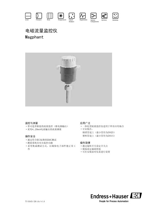
TI 036D/28/zh/v1.0Services Pressure Flow TemperatureLiquid AnalysisRegistrationSystemComponentsLevelSolutions监控与测量操作安全·带可选界限值的流量监控(继电器输出)·采用电流输出的流量测量·通过符合标准的测试·测量系统具有自监控功能·采用集成测试方式,以确保电子部件能正常工作4...20mA IEC EMC 应用广泛操作简便·一体化型流量监控仪适用于所有应用场合·可安装在:钢质管道上(最小管径为)塑料管道上(最小管径为)·通过旋转开关设定开关点·现场设定满量程值·可在安装前对仪表进行设置DN25DN15电磁流量监控仪MagphantMagphantEndress+Hauser首先,需要确认测量的工艺过程工作正常,仪表设定值不可超过其极限值。
通过检测传感器末端的电磁感应信号来进行测量。
Magphant应用实例应用场合:成套设备厂化学工业能源生产水处理饮料工业乳制品业金属生产与处理农场与园艺Magphant测量系统应用场合应用:———————————————/泵体空转保护流量监控根据流量大小进行开关切换控制泵体、涡轮、压缩机及热交换机的冷却系统流量监控泵体功能监控监控发电厂中涡轮或发电机中轴承的冷却液变压器的冷却回路对配水系统中阀体进行状态指示管道堵塞指示筛选控制清洁过程监控制冷厂中的冷却系统检测轴承及变送器的冷却系统的故障对灌溉系统进行控制与监控流量测量通风/排气系统的冷却管路根据流率大小进行开关切换监控冷却系统监控冷却系统泵体的冷却控制泵体空转保护23Endress +Hauser法拉第电磁感应定律指出在磁场中运动的导体上会生成一个感应电势。
进行流量测量时,导电液体就相当于定律中的运动导体。
乔治 费歇尔管路系统 +GF+ SIGNET 8450-1 压力变送器操作说明书
Georg Fischer Piping Systems Ltd.乔治•费歇尔管路系统有限公司 咨询热线:0755-********+GF+ SIGNET 8450-1 压力变送器操作说明书警 告!1. 在连接输入和输出时,断开电源。
2. 仔细阅读以下说明,避免人身伤害。
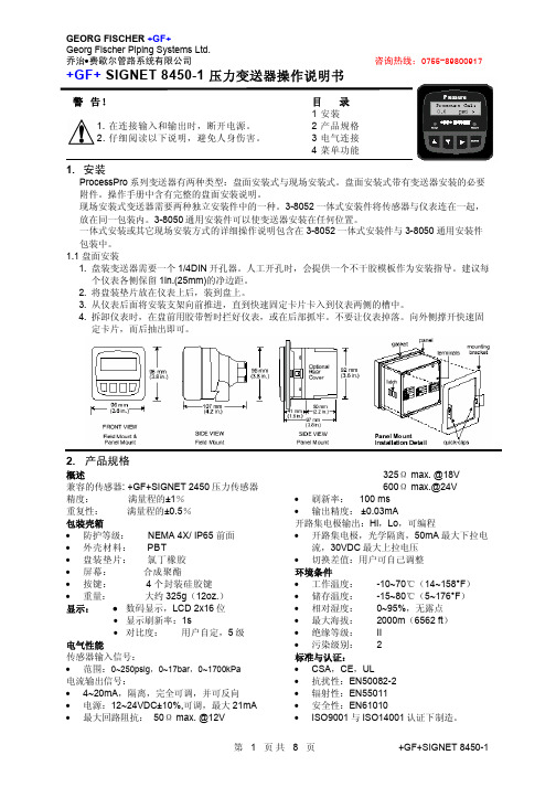
目 录1 安装2 产品规格3 电气连接4 菜单功能1. 安装ProcessPro 系列变送器有两种类型:盘面安装式与现场安装式。
盘面安装式带有变送器安装的必要附件。
操作手册中含有完整的盘面安装说明。
现场安装式变送器需要两种独立安装件中的一种。
3-8052一体式安装件将传感器与仪表连在一起,放在同一包装内。
3-8050通用安装件可以使变送器安装在任何位置。
一体式安装或其它现场安装方式的详细操作说明包含在3-8052一体式安装件与3-8050通用安装件包装中。
1.1 盘面安装1. 盘装变送器需要一个1/4DIN 开孔器。
人工开孔时,会提供一个不干胶模板作为安装指导。
建议每个仪表各侧保留1in.(25mm)的净边距。
2. 将盘装垫片放在仪表上后,装到盘上。
3. 从仪表后面将安装支架向前推进,直到快速固定卡片卡入到仪表两侧的槽中。
4. 拆卸仪表时,在盘前用胶带暂时拦好仪表,或在后部抓牢。
不要让仪表掉落。
向外侧撑开快速固定卡片,而后抽出即可。
2. 产品规格概述兼容的传感器: +GF+SIGNET 2450压力传感器 精度: 满量程的±1% 重复性: 满量程的±0.5% 包装壳箱• 防护等级: NEMA 4X/ IP65 前面 • 外壳材料: PBT• 盘装垫片: 氯丁橡胶 • 屏幕: 合成聚酯• 按键: 4个封装硅胶键 • 重量: 大约325g (12oz.) 显示: ● 数码显示,LCD 2x16位• 显示刷新率:1s• 对比度: 用户自定,5级电气性能传感器输入信号:• 范围:0~250psig ,0~17bar ,0~1700kPa 电流输出信号:• 4~20mA ,隔离,完全可调,并可反向• 电源:12~24VDC±10%,可调,最大21mA 325Ω max. @18V 600Ω max.@24V• 刷新率: 100 ms • 输出精度: ±0.03mA开路集电极输出:Hi ,Lo ,可编程• 开路集电极,光学隔离,50mA 最大下拉电流,30VDC 最大上拉电压 • 切换差值:用户可自己调整 环境条件• 工作温度: -10~70℃(14~158°F ) • 储存温度: -15~80℃(5~176°F ) • 相对湿度: 0~95%,无露点 • 最大海拔: 2000m (6562 ft ) • 绝缘等级: II • 污染级别: 2 标准与认证:• CSA ,CE ,UL• 抗扰性:EN50082-2 • 辐射性:EN55011 • 安全性:EN610103.电气连接注意:在拆除接线之前如果没有将端子插孔完全打开,可能会永久地损坏仪表。
高德瑞克公司产品用户手册说明书
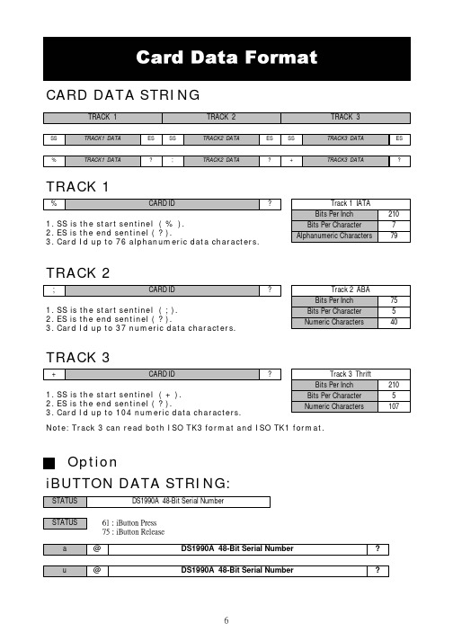
CARD DATA STRINGTRACK 11. SS is the start sentinel ( % ).2. ES is the end sentinel ( ? ).3. Card Id up to 76 alphanumeric data characters.TRACK 21. SS is the start sentinel ( ; ).2. ES is the end sentinel ( ? ).3. Card Id up to 37 numeric data characters.TRACK 31. SS is the start sentinel ( + ).2. ES is the end sentinel ( ? ).3. Card Id up to 104 numeric data characters.Note: Track 3 can read both ISO TK3 format and ISO TK1 format.iBUTTON DATA STRING:OptionSTEP 1 : Run MSR ConfigureSTEP 2 : Choose PS/2 or COM port and press “Scan” ,connect theMSR220/250 reader.START MSRCONFIGURE SOFTWAREApply the bundled disk no. 5296 to begin with the demo software.STEP3 : Click “Read” ,scan the MSR220/250 reader parameter.General :Interface : MSR Interface is being detected. Buzzer : Choose buzzer enable or disable.Feed Back : Set MSR output data ,waiting for feedback from the terminal. Show `Error 'message if no reaction from MSRRS232(UART): Setting MSR communication parameter ,when RS232 and serial USB enable .Package :Setting MSR & iButton data output package .MSR Data Package :iButton Data Package :Data Format :Keyboard : Setting MSR language ,when keybpard enable .FE1 : Package ending character.FS :Package leading character.FE0 : Package ending character.check : Bit check up.iButton: Set iButton data format .Data format :Present ID format : Set present iButton output ID format .Release ID format : Set release iButton output ID format .Family Code : Terms for iButton series.PS : iButton present prompt character.RS : iButton Release prompt character.SS : Start Sentinel ES : End SentinelFF : To set up direct side cardswipe prompt character.RR : To set up reverse side cardswipe prompt character.Swipe Card Direction : To set up prompt character for direct/reverse side card swipe prompt character.Decode Standard : To decode magstripe format.Mark Code :Leading character to set up output data.Decode Mode : To decode magstripe data.Magnetic Card: Set MSR data format and data output parameter .SS : Start Sentinel ES : End SentinelTK ES0 :Ending prompt character .TK ES1 : Ending prompt character .Track Output Order : To set up track data in turn.Track Length : To set up track data length.Head Compatible : To set up the decoding work for IBM or JIS2 data output at one time only.MSR package :JIS2 :JIS2 data format.AAMVA :AAMVA data format .IBM :IBM data format .7Bit : 7 Bits Per Character data.ABA :5 Bits Per Character data .STEP4 : Click “Write” ,write the parameter to MSR220/250 reader .Click “Open or Save” open or save your choose parameter to file. PS.Same as to when MSR220/250 reader is in RS232 interface mode,Keyboard function will be in disable mode .When MSR220/250 reader is in Keyboard function, RS232 interface will be in disable mode.STEP5 : Click “Test Mode” can test the MSR220/250 .STEP6 : Click “Default” can reset MSR220/250 parameter.。
Fisher H100 Series External Relief Valves 产品说明书

Instruction ManualD450383T012August 2016H100 SeriesH100 Series External Relief ValvesFailure to follow these instructions or toproperly install and maintain this equipmentcould result in an explosion and/or firecausing property damage and personal injuryor death.A person should NEVER stand directly overor in front of or look directly into a reliefvalve when the tank is pressurized. The reliefvalve could suddenly “pop” open blowinggas, dirt and other debris into the person’sface and eyes.Fisher™ equipment must be installed,operated and maintained in accordancewith federal, state and local codes andFisher instructions. In addition, in moststates the installation must also complywith NFPA No. 58, NFPA 501C, DOT andANSI K61.1 standards.Only personnel trained in the properprocedures, codes, standards andregulations of the LP-Gas industry shouldinstall and inspect this equipment.IntroductionScope of the ManualThis manual covers instructions for the H100 Series direct-operated relief valves which can be used in various vapor and liquid applications. Most H100 Series relief valves must be used on vapor service only. Use only advertised hydrostatic relief valves for liquid applications. The valves are typically installed in ASME tanks, DOT cylinders and piping applications.Things To Tell The Gas Customer:1. The purpose of a relief valve is to keep the tankfrom rupturing from excessive tank pressure byventing gas to the atmosphere until the tank pressuredrops. Excessive tank pressure can be caused bythe following:a. Exposure to fire or radiant heat including hotsummer days.b. New or refilled tanks not fully purged of air.c. Tank colors (other than white) increase the heatabsorption of the tank raising the pressure inthe tank.d. Propane with “vapor pressures” out of specification,i.e., “Hot Gas.”e. Overfilling the tank.2. Do not beat, pound, or hit the relief valve with hammersor other tools or attempt to force the valve closed asthis will not stop gas discharge and could damage relief valve parts or rupture the tank.3. Call your gas dealer if the relief valve discharges gas.Figure 1. H100 SeriesH110_1H185_1H173_12H100 SeriesSpecificationsThe Specifications section on this page provides the ratings and other specifications for H100 Series external relief valves. Factory specifications are engraved on the body of the relief valve at the factory.1. The pressure/temperature limits in this Instruction Manual and any applicable standard or code limitation should not be exceeded.Body Size, Tank Connection:Types H110, H120, H123, H124: 1/4 in. NPTTypes H125, H135, H144, H148: 1/2 in. NPTTypes H150, H160, H173, H174, H185: 3/4 in. NPT Maximum Allowable Relief (Inlet) Pressure (1):420 psig / 29 bar Fixed Relief Pressures:35 to 350 psig / 2.4 to 21.1 bar, see Table 1Temperature Capabilities (1):-20 to 160°F / -29 to 71°CMaterials:Body, poppet and spring retainer: Brass and Stainless steel Disk: Nitrile (NBR)Spring and retainer pin: Stainless steel Approximate Weights:H110 and H120 Series: 0.2 lb / 0.09 kg All Others: 0.4 lb / 0.18 kgIf the valve is to be for service other than LP-Gas, anhydrous ammonia, or air; contact the factory to determine if the valve materials are suitable for the particular service.Valves with brass materials must not be used on anhydrous ammonia service.TYPECONTAINER TYPECONTAINER CONNECTION, in.START-TO-DISCHARGE PRESSURE, psig / bar PRESSURE PLUSBUILDUP , psig / barFLOW CAPACITY, SCFM / SCMH airACCESSORYPipeaway AdaptorProtective CapH110-250(1)ASME1/4 MNPT 250 / 17.2- - - -310 / 527- - - -P206H125-2501/2 MNPT 250 / 17.2- - - -610 / 1036- - - -- - - -H135-250(1)- - - -594 / 1009P174(3)- - - -H150-2503/4 MNPT 250 / 17.2- - - -580 / 985- - - -- - - -H160-250(1)- - - -605 / 1028- - - -- - - -H185-250(1)- - - -2223 / 3777- - - -P145H185-275(1)275 / 19.0- - - -2456 / 4173- - - -H110-312(1)1/4 MNPT 312 / 21.5- - - -390 / 663- - - -P206H135-312(1)1/2 MNPT - - - -765 / 1300P174(3)- - - -H160-3123/4 MNPT - - - -765 / 1300- - - -- - - -H123(1)DOT or HydrostaticRelief1/4 MNPT375 / 25.9- - - -- - - -- - - -P206H148(1)1/2 MNPT - - - -903 / 1534(2)P174(3)P206H173(1)3/4 MNPT - - - -P206H120-35Hydrostatic1/4 MNPT35 / 2.460 / 4.177 / 131- - - -P206H120-6060 / 4.185 / 5.9105 / 178- - - -P206H120-120120 / 8.3145 / 10165 / 281- - - -P206H120-150150 / 10.3180 / 12191 / 325- - - -P206H120-175175 / 12.1210 / 14224 / 380- - - -P206H120-200200 / 13.8240 / 17262 / 445- - - -P206H120-225225 / 15.5270 / 19280 / 476- - - -P206H120-275275 / 19.0330 / 23303 / 515- - - -P206H120-350350 / 24.1420 / 29445 / 756- - - -P206H124(1)450 / 31.0- - - -- - - -- - - -P206H144(1)1/2 MNPT 450 / 31.0- - - -- - - -- - - -P206H174(1)3/4 MNPT 450/31.0- - - -- - - -- - - -P2061. Listed under UL ® Section 132.2. DOT cylinder water capacity 500 lbs / 227 kg, approved by Bureau of Explosives and CGA.3. 1/2 in. FNPTTable 1. H100 Series External Relief ValvesH100 Series relief valves range in size from 1/4 to3/4 in. threaded MNPT inlet connections. Set pressures and flow capacities vary by size and application. Materials of construction are typically brass, steel and stainless steel with nitrile discs. Consult your Fisher™ Catalog for size, set pressure and flow capacity combinations.UL ® listed valves are required by most states, although some states require ASME capacity rated valves. Be sure the valve is rated and stamped to meet the requirements of the state where it will be used. The valve should also have sufficient capacity for the container size where it is used.UL ® is a mark owned by Underwriters Laboratories.Vapor relief valves must be installed only in the vapor space to provide relief capacity for the tank.Installed vapor relief valves must have direct contact with the vapor space of the containers.Hydrostatic relief valves are required on liquid lines to provide relief protection for the liquid line between twoshutoff valves. Hydrostatic relief valves must be installed in the liquid space.Install the valve so that flow is unobstructed. Be certain that any discharge from the valve will not impinge on the container, adjacent containers or any source of ignition.Each application will dictate whether discharge stacks or deflectors are required. Deflectors and adaptors are separate devices mounted to the outlet of the valve to control discharge direction. Consult the applicable standard to determine if these additional devices are required.Coat the male threads of the valve with an UL ® listedsealing compound. Do not allow excess compound to drip into the container or flow around the bottom edge of the pipe threads.Pull the valve into the coupling hand tight, and then wrench tighten it for approximately two additional turns. Do not install the valve with such extreme torque that the coupling can cut threads into the valve. This could cause valve distortionFigure 2. H100 Series Operational Schematicand affect the internal working parts. Larger size valves(especially if of steel construction) may require an additional amount of torque to obtain a leak free connection.Raincaps are required on all valves. The raincap should be kept in place; an out-of-place raincap indicates the valve may have opened to relieve overpressure. Most relief valves have a drain hole in the body which must remain open at all times.Relief valves on bobtails, transports and motor fuel applications must be protected as specified by DOT,NFPA #58 and other applicable laws, codes and standards.New containers must be purged to remove air from the container. Failure to properly purge may result in excessive pressure and the possibility of “popping” the relief valve when the container is filled. Follow NFPA #58 and NLPGA Pamphlet 133-80 guidelines for purging containers.Maintenance and ReplacementSafety relief valves are non-repairable valves and cannot be adjusted in the field.Any valve that has fully opened “popped” should be tested to see if it is within theallowable start-to-discharge pressure setting. If it is not within the correct range, it must be replaced. Relief valve start-to-discharge and reseat pressures may be lower if the valve has fully opened (popped).UL ® is a mark owned by Underwriters Laboratories.4 Spring5 Poppet AssemblyFigure 3. H100 Series Assembly Drawing/EmersonProcessManagement/company/emerson-process-management /emersonprocess*******************************D450383T012 © 2016 Emerson Process Management RegulatorTechnologies, Inc. All rights reserved. 08/16.The Emerson logo is a trademark and service mark of EmersonElectric Co. All other marks are the property of their prospective owners. Fisher™ is a mark owned by Fisher Controls International LLC, a business of Emerson Process Management.The contents of this publication are presented for information purposes only, and while effort has been made to ensure their accuracy, they are not to be construed as warranties or guarantees, express or implied, regarding the products or services described herein or their use or applicability. All sales are governed by our terms and conditions, which are available on request. We reserve the right to modify or improve the designs or specifications of our products at any time without notice.Emerson Process Management Regulator Technologies, Inc does not assume responsibility for the selection, use or maintenance of anyproduct. Responsibility for proper selection, use and maintenance of any Emerson Process Management Regulator Technologies, Inc. product remains solely with the purchaser.Emerson Process Management Regulator Technologies AmericasMcKinney, Texas 75070 USA T +1 800 558 5853 +1 972 548 3574EuropeBologna 40013, Italy T +39 051 419 0611Asia PacificSingapore 128461, Singapore T +65 6770 8337Middle East and Africa Dubai, United Arab Emirates T +971 4 811 8100。
NOV FGS 产品数据册说明书

Uses and applications• A cid drains • Bleach processing • Chemical process piping • Chlorinated water • Chlorine • Corrosive slurries • Food processing plant • Organic chemicals• Oxidizing chemicals and acids • Phosphoric acid• Water Treatment/Purification• General industrial service for severely corrosive liquidsThe service temperature and concentration limitation for each chemical mixture shall be cross referenced to NOV FGS Chemical Resistance Guide.ListingsClassification approval from LRS, DNV, ABS, BV and NK.PerformanceWorking pressure from 150 to 232 psig (10 to 16 bar) depending on pipe size.Operating temperatures up to 180°F (82°C). Subzero temperatures will not adversely affect mechanical properties.Excellent corrosion resistance over a wide temperature range. See most recent release of Bondstrand Corrosion Guide for specific applications.Does not require thrust blocks at ambient temperatures when properly installed in most soils.Smooth inner liner (Hazen-Williams C = 150) produces extremely low frictional loss for greater discharge and reduced pumping costs.Low thermal conductivity minimizes heat losses.Optional: The product can be supplied in conductive type - Bondstrand 5000C for ConductiveBondstrand 5000/5000C Product Data(Severely Corrosive Industrial Service and Oxidizing Acids)Example of standard Quick-lock plus overwrap joint view1-625-150RTRP 11FW-1012/11FE-10128-16200-400RTRP 11FW-1013/11FE-10131 - 11/2 25 - 40 3.02- 650 - 1509.08 - 16200 - 40011.89CompositionPipeFilament-wound fiberglass-reinforced vinylester pipe with integral 0.050-inch (1.3 mm) resin-rich reinforced liner.FittingsFilament wound fiberglass reinforced vinyl ester fittings with integral 0.050 inch (1.3 mm) resin rich reinforced liner. Following types of fittings available as a standard.Tees90° and 45° elbows CrossesNipples and couplings 45° laterals ReducersFlanges and BlindLaminated or molded flanges with ASME/ ANSI / JIS/ DIN standard drilling. Other flange bolt drilling standard available upon request.Thermosetting adhesivesRP106 two-parts Vinylester resin and cure for 5000/5000CJoining systemsQuick-Lock® straight/taper adhesive-bonded joint featuring integral pipe stop in bell for predictable, precise laying lengths plus overwrap on joint for enhanced joint performance.Pipe lengths end-to-endStandard pipe length (end-to-end) will have one shaved male ends and one integral female end. Pipe end with both plain ends supply is upon specific order requested.FittingsReducers, couplings, tees and 90° & 45° elbows are available with integral Quick-Lock female end. Plain end fittings are available upon specific order requested.Laying lengths of filament-wound fittings with Quick-Lock ends to be refer to product dimensions table (PDT).Typical pipe dimensions and weights125 1.0727.30.138 3.50.533400.40.6 11/240 1.6742.30.138 3.50.795100.610.9 250 2.1053.00.134 3.4 1.13730 1.0 1.2 380 3.2282.00.138 3.5 1.701100 1.5 1.7 4100 4.14105.00.178 4.5 2.731760 2.4 2.8 5125 5.19131.90.178 4.5 3.001928 3.1 3.8 6150 6.20159.00.178 4.5 4.062620 3.5 4.2 82008.22209.00.197 5.0 5.833760 5.0 6.1 1025010.35263.00.197 5.07.314710 6.27.7 1230012.35314.00.224 5.78.8657197.49.1 1435013.56344.00.221 5.610.8570008.711.0 1640015.50394.00.252 6.414.18915011.214.0 1) Total wall thickness is combined of minimum structural wall thickness plus 1.3mm liner.1) Use these values for calculating longitudinal thrust.Typical pipe performance125232162191.215.1111/24023216689.5 4.76 25023216318.7 2.20 38023216109.50.76 410023216160.1 1.10 51252321683.80.58 61502321648.90.34 82001751234.00.23 102501751217.30.12 123001451217.30.12 143501451012.30.08 164001451013.70.091) External pressure at 70°F (21°C)2) Internal pressure at 150°F (65°C)Fittings pressure ratingFittings and flanges will have same product pressure rating as pipe.Bushed saddles used Bondstrand Series 2000M epoxy saddles with 316 stainless steel outlet. Other outlet material available on special order.Reducer bushings bonded into flanges/ saddles will have the same product rating as the flanges/ fittings unless otherwise shown in the products table.Field testingBondstrand 5000/5000C piping systems are designed for hydrostatic field testing at 150% of rated design pressure. Pneumatic testing is not recommendedTypical mechanical propertiesTensile strength Longitudinal 103 psiMPa10.874.5D2105Tensile strength Circumferential 103 psiMPa77.253.2D1599Tensile modulus Longitudinal 103 psiMPa2.7919.24D2105Tensile modulus Circumferential 103 psiMPa3.9427.17-Long-term hydrostatic(2) Design basis Static, Hoop Stress LCL 20 Year Life @150°F (65°C)103 psiMPa12.888.3D2992(B)Poisson’s Ratio(3) V ah-0.32-Poisson’s Ratio(3) V ha-0.61-(1) B ased on structural wall thickness, at ambient temperature unless noted.(2) T est fixtures were “free end” type. Specimens were stressed by internal pressure in both hoop and longitudinal directions.(3) V ha = The ratio of axial strain to hoop strain resulting from stress in the hoop direction.V ah = The ratio of hoop strain to axial strain resulting from stress in the axial direction.Typical physical propertiesThermal conductivity Btu-in/(h•ft2 • ° F )W/m•°C2.00.28C177Coefficient of thermal expansion(linear) (2 -16 inch) 77°F to 150°F (25°C to 65°C)10-6 in/in/°F10-6 cm/cm/°C1018D696Flow coefficient Hazen-Williams150.00-Absolute roughness 10-6 ft10-6 m17.405.30-Specific gravity- 1.80D792Density lb/in3Kg/m30.0651840-Pipe stiffness12534038.4154010.6091.3629655 11/24034038.4154010.6028.7198132 25034038.4154010.6013.391586 38034038.4460 3.20 4.631471 410082092.6530 3.70 6.745992 512555662.9187 1.29 3.524091 615082092.6160 1.10 2.114053 82001180133.31050.72 1.49770 102501180133.3530.370.724984 123001447163.5380.270.724957 143501330150.2360.250.513520 164002190247.4380.260.5739371) Per ASTM D24122) STIS is referring to Specific Tangential initial Stiffness (Stiffness Class).Span lengthsRecommended maximum support spacings for Bondstrand 5000/5000C vinyl ester pipe at various operating temperatures. Values based on 0.5-inch (12.5 mm) deflection at midspan for fluid specific gravity = 1.0. For fully continuous spans, values may be increased up to 20%. Decrease values by 20% for single spans.1259.38.98.711/24010.710.29.225012.110.89.438013.712.310.7410016.114.512.6512517.015.213.3615018.116.114.2820020.118.115.51025021.419.216.61230022.320.217.51435023.120.718.11640024.321.618.91) Span recommendations are intended for normal horizontal piping support arrangements, but include no provision for weights (fittings, valves, flanges, etc) or thrusts (branches, turns, etc.).2) Span recommendations are calculated for a maximum long-term deflection of 1/2 inch to ensure good appearance and adequate drainage.Fiber Glass Systems17115 San Pedro Avenue, Ste. 200, San Antonio, Texas 78232, USAPhone: 210 477 7500 Fax: 210 477 7560NOV Inc. has produced this brochure for general information only, and it is not intended for design purposes. Although every effort has been made to maintain the accuracy and reliability of its contents, NOV Inc. in no way assumes responsibility for liability for any loss, damage or injury resulting from the use of information and data herein nor is any warranty expressed or implied. Always cross-reference the bulletin date with the most current version listed at the web site noted in this literature. January 2022, CI5000ENG。
GF电磁流量计探头说明书

1.4bar@85℃ (20psi@185℉)
工 作 压 力
介质温度
检测、认证与标准 • NEMA 4X • CE
EN 61326: 控制设备的抗扰性与辐射性 外形尺寸
适用于 1/2”~4”管道
接好。用电线(推荐使用的电
线规格为 14AWG/1.5mm2)
仪表
将这个接地端子直接连到现场
的地上。
电缆屏蔽层不要在 流量计一端接地
② 在流量计的上下游加装介质接 地设备,并将其与 2551 外壳 上的接地端子连在一起。
如果是塑料管道,介质接地设 备可以是接地法兰环或金属电 极,如果是金属管道,介质接 地设备可以是金属卡子。
精确位置。各种安装管件的完整订货号可以在 10-14 页上查到。
管件种类
描述
管件种类
描述
塑料三通
• 0.5”-4” • PVC 或 CPVC
钢制,碳钢, 316 不锈钢螺 纹三通
• 0.5”-2” • 安装在带螺纹的管端上
公制活接管件
• 适用管径 DN15-DN50 • PP 或 PVDF
碳钢或不锈钢 的直焊管件
5. 2551 流量计的构造
无论您使用的流量计是 2551-XX-11(频率信号或数字 S3L 信号) 还是 2551-XX-12(4~20mA 信号),其黄 色盒盖内部的接线端子都是一样的。流量计与外部设备(PLC、记录仪、指示仪等)的所有接线都连在 较大的四孔端子块上。 打开盒盖,可以看到传感器的导线被接在更小的端子块上。这些接线不要做改动,以防止无意的破坏或 错接。 2551 电磁流量计接线端子可以连接的导线线径规格为 16AWG - 22AWG。
- 1、下载文档前请自行甄别文档内容的完整性,平台不提供额外的编辑、内容补充、找答案等附加服务。
- 2、"仅部分预览"的文档,不可在线预览部分如存在完整性等问题,可反馈申请退款(可完整预览的文档不适用该条件!)。
- 3、如文档侵犯您的权益,请联系客服反馈,我们会尽快为您处理(人工客服工作时间:9:00-18:30)。
Beta (b) Polypropylene . . . the better PPBeta (b) Polypropylene Piping Systems• Pipe, Valves, Fittings and Flow Control• Sizes 16 mm (3/8") through 315 mm (12")• IR™/Butt and Socket Fusion JoiningTable of ContentsBeta (b)Polypropylene Piping Systems Introduction...............................................................................................................................................................................................5.4 Polypropylene Applications..............................................................................................................................................................5.10 Polypropylene Working Temperatures and Pressure for Pipe and Fittings........................................................................5.12 Flow Rate versus Friction Loss – PP pipe........................................................................................................................................5.13 Friction Loss through PP Fittings........................................................................................................................................................5.15 SDR11 Polypropylene vs. Schedule Pipe Dimensions...............................................................................................................5.15 Determining the Length Changes in PP Pipelines.......................................................................................................................5.16 The Incorporation of Expansion Joints...........................................................................................................................................5.22 The Installation of Pipework under Plaster or Embedded in Concrete...............................................................................5.22 Pipe Bracket Support Centers and Fixation of Plastic pipelines............................................................................................5.23Beta (b) Polypropylene Butt and IR™ (Infrared) Fusion Joining Technology Polypropylene Piping Specification for the Institutional, Pharmaceutical and Food Industries...................................5.25 Butt and IR Fusion Pipe and Fittings Dimensions.........................................................................................................................5.28 Butt and IR Polypropylene Valves....................................................................................................................................................5.43 Butt and IR Joining Machines...........................................................................................................................................................5.45Beta (b) Polypropylene Socket Fusion Joining TechnologyPolypropylene Piping Specification for the Chemical and Plating Industries...................................................................5.47 Socket Pipe and Fittings Dimensions..............................................................................................................................................5.50 Socket Valves.........................................................................................................................................................................................5.61 Socket Fusion Joining Machines......................................................................................................................................................5.63Good TemperatureResistanceThe George Fischer polypropylenepiping system is pressure rated to 150psi (10 bar) at 70°F (21°C) with a longterm safety factor of 2.1. The upper longterm temperature limit for polypropyleneis 176°F (80°C) and the temperature limitfor short term use is 212°F (100°C).However, as with all thermoplasticpiping systems, an increase in tempera-ture is combined with a decrease inoperating pressure.Chemical ResistanceThe chemical resistance properties ofpolypropylene are excellent. It is resistantto aqueous solutions of acids, alkalisand salts and to a large number oforganic solvents. This wide range ofchemical resistance allows this materialto be used for many piping systems thathandle different chemicals includingcaustics, acids and solvents. Polypro-pylene is not suitable for handlingconcentrated oxidizing acids andhalogens.IntroductionPolypropylene is one of the mostcommon, fastest growing and versatilethermoplastics currently used. Eachyear many tons of this material areconverted into diverse products rangingfrom plastic bags through automobileparts to tanks and chemical pipingsystems.From a chemical standpoint, polypro-pylene is closely related to polyethyl-ene. As members of the group ofmaterials known as “polyolefins”, bothof these plastics are composed of onlycarbon and hydrogen. This contrastswith other commonly used plasticmaterial such as PVC and PTFE whichcontain chlorine and flurorine respec-tively.Physical PropertiesThe physical properties of polypropy-lene combine strength, low weight,abrasion resistance, impact strengthand a wide operating temperaturerange, making it a very suitable mate-rial for use in load bearing products.Combined with excellent all roundchemical resistance and low waterabsorption, these properties combine toprovide a material that meets all of therequirements for use in a piping system.PurityGeorge Fischer polypropylene complieswith guidelines listed in the FederalRegister, CFR Title 21, chapter 1, §177.1520 a (1) for polypropylene and c(1.1) for compounds. George Fischerpolypropylene is suitable for transportof potable water, foodstuffs, and highpurity deionized water.Beta (b) Polypropylene Piping for Industrial ApplicationsDaplen Beta (b )-PP ... the Greater Safety and EconomyDaplen Beta (β)-PP is a polypropylene homopolymer with an exceptionally homogeneous, fine structure and significantly higher impact strength.The high degree of crystallinity of these substances ensures an excellent resistance to chemicals. This is further improved by the titanium dioxide pigment used.The long-term creep strength was assured by endurance tests inaccordance with ISO TR 9080 and certified with the value MRS 10(minimum required strength).Conventional PP homopolymer surface magnified 200 timesDaplen Beta (b )-PP surface magnified 200 timesImpact Bending Test to DIN 8078Hammer 50 J instead of 15 J Pipe 110 mm x 10 mBehavior of Daplen Beta (b )-PPRegression curves to ISO TR 9080LTHS LCLTest interruptedMeasurements andcalculations (SEM) from TGM plastics technologyDaplen Beta (b PPPP-H conven-tionalIn contrast with conventional PP homopolymers, Beta (b )-PP possesses a superior impact strength – both at room temperature and also at low temperatures.C o m p a r a t i v e s t r e s s (N /m m 2)We offer a complete range of plasticpiping components, including pipes,fittings (socket and butt-fusion fittings),manually operated valves andactuated valves in one material.In addition to the outstandingcharacteristics of polypropylene homo-polymer, this also provides unlimitedcompatibility for the mutual weldabilityof various PP types for users and finalconsumers.Beta (β)-PP combines all the requiredfavorable properties for modernindustrial pipeline construction,including:• Excellent resistance to chemicals• High impact strength• High thermal resistance• High stress crack resistance• Excellent fusion capability• Homogeneous, fine structureThe pipes comply in all features withDIN 8077/8078 type 1.The many years of process know-howacquired by the two companiesGeorge Fischer Piping Systems andDEKA Pipe Systems provides the idealproduct package from an outstandingraw material for processors and plantoperators.Extruded pipes and precisionmolded fittingsAn innovative extrusion process ensuresoptimum conversion of the rawmaterial potential to a high-grade pipeproduct with minimum internal stresses.The special method of processingachieves extremely smooth internalsurfaces in the pipes, which are in noway inferior in topography to injectionmoldings.Your benefit in applicationComprehensive tests bear witness tothe special barrier effect of ahomogeneous and fine-crystalline pipewall construction with regard tointeraction with a wide range ofmedia. The significantly improvedinternal surface further substantiallyincreases the resistance of the pipes tochemicals. The resulting optimized flowbehavior reduces the danger oferosion and deposition.All in one material -Daplen® Beta (b)-PPOptimum processing for thebetter materialLow internal stressMicrotome section magnified40 timesRa measuring curve for the pipeinternal surface measured by anon-contact laser process in theextrusion directionPipes after a test series withchromic acid magnified 600times under the scanningelectron microscope.Conventional PP-HDEKAPROP Beta (b)-PPComplete System of Pipe,Valves and FittingsThe George Fischer polypropylenepiping system is available in sizes from3/8" to 12". The system includes valvesthrough 12."This system includes all commonlyrequired pressure pipe fittings, includingthreaded adaptors and flanges forease of mating to equipment or otherpiping materials. Ball valves areavailable in sizes 3/8" to 6", dia-phragm valves from 1/2" to 6" andbutterfly valves in sizes 2 1/2" to 12".Other valves including check valvesand metering valves are also availablein this system.Fusion Joining ReliablityAssembly and joining of this system isperformed by heat fusion. Fusion jointsare made by heating and melting thepipe and fitting together. This type ofjoint gives a homogeneous transitionbetween the two components withoutthe lowering of chemical resistanceassociated with solvent cement joiningand without the loss of integrity andloss of pressure handling ability of athreaded joint.Three different fusion methods forpolypropylene are available andcommonly used in today's demandingapplications. These include socketfusion, regular butt fusion, and Infrared(IR) fusion.Socket Fusion Joining can be used tojoin socket fusion fittings available insizes 16-110mm (3/8"-4"). The socketfusion method of joining uses a heatednon-stick “female” bushing to melt theoutside of the pipe end and a heatednon-stick “male” bushing to heat theinside of the corresponding size offitting. After several seconds, when theoutside of the pipe and the inside ofthe fitting are melted, the bushings areremoved and the pipe is pushed intothe fitting. Due to the large area ofpipe to fitting contact (3-5 times thecross sectional area of the pipe), theresulting joint is actually several timesstronger than the pipe itself. The pipeand fittings for this system are alsomanufactured to have an interferencefit; because of this interference it is notpossible to slide a fitting over the pipewithout the use of heat to melt thesurface to be joined. This featureprevents the possibility of inadvertentlyleaving a joint unfused, and moreimportantly causes displacement ofsome material during fusion therebyguaranteeing a high strength, reliable,reproducible joint.Acid neutralization facilityuses George Fischerpolypropylene piping andvalves in overheadinstallation.For a complete guide toproper installation techniques,the George Fischer factorysponsored installer certifica-tion program is recommended.It teaches a basic understand-ing of plastics and fusiontechnology. For moreinformation, contact yourGeorge Fischer representative.smaller and lower stresses due to very uniform heating. This method is available for pipe sizes 1/2" (20mm) through 9"(225mm).IR Plus™ Advantages:• Non-contact heating• Smaller internal and external beads repeatability • Low stress joint• Ease of operation due to fully automated fusion machinery• Automatic fusion joining record (if desired) using optional printerPiping System DesignAs with all piping systems, proper selection and design is necessary to ensure that a successful installation can be made. Before using this polypro-pylene piping system, the user should ensure that the polypropylene issuitable for contact with the liquids to be handled. This information may be readily found in a chemical resistance chart. If polypropylene is chemically compatible and the operating tem-perature and pressure are within the previously discussed limits, then the system may be used. However it should be designed to include allowances for expansion andcontraction, pressure drops and proper pipe support.Length changes in plastic pipelines are commonly caused by thermal expansion due to changes in ambienttemperature and changes in the tem-perature of the media being handled.The length change for polypropylene will be 0.0000837 inches per inch of length per degree Fahrenheit tempera-ture change. So if the temperature of a 100 foot straight length of pipe is raised from 30°F (-1°C) to 80°F (27°C)it would grow by 5 inches. The pipe-line must be installed in such a way that this expansion can be accounted for. Common practice is to use either expansion loops or change of direction to achieve this. In both of these cases,a length of pipe running perpendicular to the change in length is used to absorb the expansion by being bent.IR Plus ™ Infrared Butt Fusion Joining is an ideal method to join IR fusion fittings in the size range of 20-225mm (1/2"-9") to achieve the maximum joint consistancy. Regular butt fusion can also be used to join IR and butt fusion fittings in the size range of 20mm and up.Butt fusion pipe and fittings both have the same inside and outside diameters.To make a butt fusion joint, the pipe and fitting are clamped so that the ends to be joined are facing each other. The ends are then "faced" flat and parallel. A flat heating plate is used to simultaneously heat both faces to be joined. When each end is molten the heating plate is removed and the pipe and fitting are brought together. Joining is achieved by fusion between the molten materials.George Fischer is constantly searching for and developing new joining proce-dures to improve mechanical strengths,ensure repeatability, and simplifyoperation. A recent development is the George FischerIR Plus™ (Infrared) Fusion System Using the new, fully automated, digital indicating fusion machinery, highstrength butt fusion joints can be made with many advantages over the con-ventional, pressure type butt fusion methods. A non-contact, IR heating plate is used, along with apredetermined overlap to join the pipe (or fitting) ends together to eliminate operator error and provide a reliable,reproducible, high strength joint withFor a complete guide toproper installation techniques,the George Fischer factory sponsored installer certifica-tion program is recom-mended. It teaches a basic understanding of plastics and fusion technology. For more information, contact your George Fischer representative.George Fischer polypropylene is used at a caustic handling facility.Polypropylene ApplicationsWasteOver a period of many years, polypro-pylene has become a preferredmaterial for handling many differenttypes of liquid waste. This material’swide range of chemical resistancemakes it very suitable for handling thewide range of different chemicals andmixtures that are found in differentwaste streams. The unsuitability ofpolypropylene for use with concen-trated oxidizing acids is generally nota problem because these acids willusually be diluted before they aredisposed of. The high resistance ofpolypropylene to solvents is particu-larly important, because many solventsdo not mix in water and often end upfloating in a concentrated form nearthe top of the pipe. Thus, eventhough a waste stream may containonly 1% of a solvent, it is often notpossible to regard this dilution be-cause most of the solvent will oftenfloat to the top of the pipe. Thematerial’s high temperature capabilitiesare also important in enabling it tohandle any exothermic reactions thatmay occur when different chemicalsmix.Pressure drop calculations are used toensure correct pipe and pump sizing.By summation of pressure drop figuresthrough each length of pipe, fittingand valve, a total value for the systemcan be found.This value can be used to help inpump selections. If the value is toohigh for the available pumps, then useof larger diameter pipe, fittings andvalves should be recommended todecrease the allowed pressure dropfor the chosen flow rate.Correct support is also necessary toprevent sagging and damage to thepipe. The distance between the pipebrackets depends upon the pipediameter and the specific gravity of themedia as well as the maximumworking and ambient temperatures. Ifthe media to be handled is hot, then itis often advantageous to providecontinuous horizontal support by layingthe pipe within V or U shapedchannels, made of metal or a heatresistant plastic. Pipe clamps shouldpreferably be made of plastic, andshould allow longitudinal movement ofthe pipe. Pipe clamps that clamptightly onto the outside of the pipe donot allow proper expansion and maycause damage to the pipe.Butt fusion fittings areavailable in sizes 1/2”through 12”.Deionized WaterLarge volumes of distilled or deionized water are used by a wide range of different industries. This water is often used for diluting chemicals, washing and rinsing. Polypropylene is commonly used as a piping material for conveying this water. Although it does not have the ultra-purity of PVDF, polypropylene piping systems are able to maintain the purity required in all but the most demanding installations. Fusion joining gives fast reliable joining without the use of hazardous and noxious solvents that may contaminate the water. The total quantity of added lubricants and organic materials in polypropylene is far less than found in many other plastic piping materials. The use of a pig-mented material is recommended to reduce degradation of the pipe material from ultraviolet light. The pigmented pipe wall will prevent the transmission of ambient light into the pipe material. This prevents possible degradation of the pipe wall and corresponding particulation of plastic into the water stream.Caustic SolutionsThe chemical resistance of polypro-pylene to caustic solutions such as potassium hydroxide and sodium hydroxide is very good. The fusion joining method gives strong joints that are resistant to attack by these strongly caustic solutions. This contrasts to solvent cemented joints which may be attacked by some caustic solutions. For these reasons polypropylene is often used to trans-port caustic soda used for neutralizing acidic waste streams.General Chemical HandlingThe wide range of chemical resistance of polypropylene makes it suitable for use in applications where a piping system may be required to carry different chemicals or mixtures of chemicals. In this case polypropylene is often found to be one of the most suitable materials for handling combi-nations of many chemicals.Polypropylene Working Temperatures and Pressures for Pipe and FittingsBased on 25-year service life. Design factor C=2.0Flow V ∆H ∆P V ∆H ∆P V ∆H ∆P V ∆H ∆P V ∆H ∆P Flow Rate Rate (GPM) 16 mm 20 mm 25 mm 32 mm 40 mm (GPM)1 1.72 3.23 1.40 1.00 .88.38.63.29.12.35.09.0412 3.4311.64 5.04 2.01 3.16 1.37 1.27 1.03.45.70.32.142 58.5863.5427.51 5.02 17.257.47 3.17 5.63 2.44 1.93 1.72.75 1.22.57.255 712.01118.4951.307.03 32.1613.92 4.4410.50 4.55 2.63 3.21 1.39 1.67 1.07.467 1017.16229.3899.3010.04 62.2626.95 6.3420.338.80 3.86 6.22 2.69 2.44 2.07.9010 1515.06131.9357.119.5043.0818.65 5.7913.18 5.71 3.67 4.38 1.9015 2012.6773.4031.777.7222.469.72 4.897.47 3.2320 259.8233.9614.70 6.2211.29 4.8925 3011.7547.5920.607.4415.83 6.8530 358.6721.069.1235 409.8926.9711.6840 4511.1133.5414.5245Flow V ∆H ∆P V ∆H ∆P V ∆H ∆P V ∆H ∆P V ∆H ∆P Flow Rate Rate (GPM)50 mm 63 mm 75 mm 90 mm 110 mm (GPM) 1122 5.78.19.08.49.06.03.35.03.0157 1.06.36.16.67.12.05.47.05.02710 1.56.69.30.99.23.10.69.10.04.48.04.02.32.02.011015 2.34 1.47.64 1.48.49.21 1.04.20.09.72.08.03.48.03.011520 3.12 2.51 1.09 1.97.82.35 1.39.35.15.96.14.06.64.05.022025 3.97 3.79 1.64 2.51 1.23.53 1.77.53.23 1.22.21.09.82.08.032530 4.75 5.31 2.30 3.00 1.73.75 2.11.74.32 1.46.30.13.98.11.053035 5.537.07 3.06 3.50 2.30 1.00 2.46.98.42 1.70.40.17 1.14.15.063540 6.319.05 3.92 3.99 2.94 1.27 2.81 1.26.55 1.94.51.22 1.30.19.0840 457.0911.26 4.87 4.48 3.66 1.58 3.15 1.57.68 2.18.64.28 1.46.24.1045 507.8713.69 5.93 4.98 4.45 1.93 3.50 1.90.82 2.42.78.34 1.62.29.1350 609.5019.188.30 6.01 6.24 2.70 4.23 2.67 1.16 2.93 1.09.47 1.96.41.1860 7011.0625.5211.05 6.998.30 3.59 4.92 3.55 1.54 3.41 1.45.63 2.28.54.2370 807.9810.62 4.60 5.61 4.64 2.01 3.89 1.85.80 2.60.70.3080 908.9713.21 5.72 6.31 5.65 2.45 4.37 2.30 1.00 2.92.87.3890 10010.0016.06 6.957.03 6.87 2.97 4.87 2.80 1.21 3.26 1.05.45100 1258.7710.39 4.50 6.07 4.23 1.83 4.06 1.59.69125 15010.5414.56 6.307.29 5.93 2.57 4.88 2.23.97150 1758.517.89 3.42 5.69 2.97 1.29175 2009.7410.11 4.38 6.51 3.80 1.65200 25012.1615.28 6.618.13 5.74 2.48250 3009.758.05 3.48300 35011.3910.71 4.64350Hazen and Williams EquationV=Fluid velocity, ft/sec∆H=Head loss, ft H2O per 100 ft pipe∆P=Head loss, psi per 100 ft pipeC=150ID=Inner Diameter of pipe in inchesFlow Rate versus Friction Loss - Polypropylene Pipex)V=4 Q (.1337)60π D 212(∆P=∆GPM1.852ID4.8655()1.852∆H=.2083100C()Flow Rate versus Friction Loss – Polypropylene PipeFlow V∆H∆P V∆H∆P V∆H∆P Flow Rate Rate (GPM)160 mm200 mm225 mm(GPM) 25 .39 .01 .01 .25 .00 .00 .19 .00 .00 25 50 .77 .05 .02 .49 .02 .01 .39 .01 .00 50 100 1.54 .17 .07 .98 .06 .03 .78 .03 .01 100 150 2.31 .36 .16 1.48 .12 .05 1.17 .07 .03 150 200 3.08 .62 .27 1.97 .21 .09 1.56 .12 .05 200 260 4.01 1.00 .44 2.56 .34 .15 2.02 .19 .08 260 300 4.62 1.31 .57 2.95 .44 .19 2.34 .25 .11 300 360 5.55 1.84 .79 3.55 .62 .27 2.80 .35 .15 360 400 6.16 2.23 .97 3.94 .75 .33 3.11 .42 .18 400 450 6.93 2.77 1.20 4.43 .93 .40 3.50 .53 .23 450 500 7.70 3.71 1.46 4.92 1.14 .49 3.89 .64 .28 500 550 8.47 4.02 1.74 5.42 1.35 .59 4.28 .77 .33 550 600 9.24 4.73 2.05 5.91 1.59 .69 4.67 .90 .39 600 70010.78 6.29 2.72 6.89 2.12 .92 5.45 1.20 .52 700 80012.328.05 3.49 7.88 2.71 1.17 6.23 1.53 .66 800 900 8.86 3.37 1.46 7.01 1.90 .82 900 1000 9.85 4.10 1.77 7.79 2.31 1.001000 120011.82 5.74 2.49 9.34 3.24 1.401200 140010.90 4.32 1.871400160012.46 5.53 2.391600 250 mm280 mm315 mm100 .63.02.008.5.011.005.4.006.003100 150 .95 .041.018 .75.024.01.6.013.006150 200 1.26 .07.03 1.01.041.018.79.023.01200 300 1.89.149.065 1.51.086.037 1.19.048.021300 400 2.52.254.11 2.01.146.063 1.59.082.036400 500 3.15.384.166 2.51.221.096 1.99.125.054500 600 3.79.539.233 3.02.31.134 2.38.175.076600 700 4.42.717.31 3.52.412.178 2.78.233.101700 800 5.05.918.397 4.02.528.229 3.18.298.129800 900 5.68 1.141.494 4.52.657.284 3.57.37.16900 1000 6.31 1.387.601 5.03.798.345 3.97.45.1951000 1200 7.57 1.944.842 6.03 1.119.484 4.77.631.2731200 1400 8.83 2.587 1.12 7.04 1.488.644 5.56.839.3631400 160010.09 3.313 1.434 8.04 1.906.825 6.361.075.4651600 180011.36 4.12 1.784 9.05 2.371.0267.151.337.5791800 200012.62 5.008 2.16810.05 2.8811.2477.941.625.7032000 240015.147.019 3.03912.06 4.0381.7489.532.278.9862400 280017.679.339 4.04314.07 5.3722.32611.12 3.031.3122800 320020.1911.959 5.17716.08 6.8792.97812.71 3.88 1.683200Friction Loss through Polypropylene FittingsIn equivalent length of pipe, feetPipe outside3/8"1/2"3/4"1"11/4"11/2"2"21/2"3"4"6"8"9" diameter16mm20mm25mm32mm40mm50mm63mm75mm90mm110mm160mm200mm225mm 90° elbow0.9 1.52 2.7 3.5 4.2 5.57811162022.5 45° elbow0.50.81 1.3 1.7 2.1 2.7 3.54 5.581011.2 Tee with0.6 1.0 1.4 1.7 2.3 2.7 4.3 5.1 6.38.31316.518.6 flow through runTee with flow 1.8 4.0 5.1 6.0 6.98.112.014.316.322.1324045 through branchReducer bushing – 1.0 1.1 1.2 1.4 1.7 2.6 3.6 4.4 5.271011.2 (one reduction)Male/Female0.5 1.0 1.3 1.6 2.2 2.6 3.5––––––AdaptorSDR 11 Polypropylene vs Schedule Pipe DimensionsSDR 11 PP O.D.I.D.cross section area area ratioOD ID area SDR 11Sch 40Sch 80SDR 11Sch 40Sch 80SDR 11Sch 40Sch 80SDR 11 vs.closest mm mm cm2inch inch inch inch inch inch inch2inch2inch2Sch 40Sch 80inch size 16 12.4 1.208 .630 .675 .675 .488 .493 .423 .187 .191 .141 .979 1.3263/820 16.2 2.061 .787 .840 .840 .638 .622 .546 .320 .304 .234 1.053 1.3681/225 20.4 3.269 .984 1.050 1.050 .803 .824 .742 .506 .533 .432 .949 1.1713/432 26.0 5.309 1.260 1.315 1.315 1.024 1.049 .957 .824 .864 .719 .954 1.146140 32.6 8.347 1.575 1.660 1.660 1.283 1.380 1.278 1.293 1.496 1.283 .864 1.008 1 1/450 40.813.074 1.969 1.900 1.900 1.606 1.610 1.500 2.026 2.036 1.767 .995 1.147 1 1/263 51.420.750 2.480 2.375 2.375 2.024 2.067 1.939 3.217 3.356 2.953 .959 1.089275 61.2 29.417 2.953 2.875 2.875 2.409 2.469 2.323 4.558 4.788 4.238 .952 1.076 2 1/290 73.6 42.545 3.543 3.500 3.500 2.898 3.068 2.900 6.596 7.393 6.605 .892 .9993110 90.0 63.617 4.331 4.500 4.500 3.543 4.026 3.826 9.85912.73111.497 .774 .8574 125102.282.034 4.921** 4.024**12.718** *** 140114.4102.79 5.512 5.563 5.563 4.504 5.047 4.81315.93320.00518.193 .796 .8765 160130.8134.37 6.300 6.625 6.625 5.150 6.065 5.76120.83128.89026.066 .721 .7996 200163.6210.217.8748.6258.625 6.4417.9817.62532.58350.02745.663 .651 .7148 225184.0265.908.858** 7.244**41.214****9250 **204.4328.139.84310.75010.7508.04710.0209.56450.85878.85471.840.645.70810*No U.S. equivalent size** For Reference onlymin. distance = ∆ I max. +5 mm .20 in.Allowing for length changes in PP pipelinesGeneralVariations in temperature cause greater length changes in thermoplastic materials than in metals. In the case of above-ground, wall or duct mounted pipework,particularly where subjected to varying working temperatures, it is necessary to make suitable provision for length changes in order to prevent additional stresses.Length changes can be taken up by the following means:a. Flexible sections b. Expansion jointsThe flexible section is used most frequently,as it is the simplest and most economical method. The calculation and positioning of flexible sections are, therefore, de-scribed in detail.Coefficient of linear expansion δ of various materialsx10 - 6 St Cu GFK AI PVC PP PEFundamentalsIt is possible to take advantage of the very low modulus of elasticity of PP by includ-ing special sections of pipe which com-pensate thermal length changes. The length of the flexible section mainly de-pends upon the pipe diameter and the extent of the length change to be com-pensated. In order to simplify planning and installation, the third influencing fac-tor—the pipe wall temperature —is not taken into account, particularly as instal-lation usually takes place in the tempera-ture range between 5° and 25°C (41° and 77°F).Where the pipework changes direction or branches off there is always a natural flex-ible section. Movement of the flexible sec-tion a caused by the length change ∆ l must not be impeded in the area con-cerned by too tightly mounted pipe brack-ets, jutting brickwork, girders or similar.St Cu AI GFK PVC PP PECalculation and Positioning of Flexible SectionsModulus of elasticity of various materials E x103kp/cm 2min. distance = ∆ I max. +5 mm .20 in.。