南开大学光学工程内部课件Oct 19th
合集下载
南开大学光学工程内部课件Sep 7th
Brief history of optics (cont’ed)
平面镜 (《经下》19/—/42· —) 经:景迎日。说在转。 影子可以由反射(迎)太阳(的光线)形 成。理由在于翻转
经说:景,日之光反烛人,则景在日与人之间。
如果太阳之间
Brief history of optics (cont’ed)
母国光 战元龄著 《光学》 人民教育出版社
参考书目
ftp://202.113.227.137 Username: optics Password: optics-nk
/opt/index/
/course/optics/
《淮南万毕术》,公元前120左右,淮南王刘安及 其门客的著作。记录了用冰制作透镜的方法: “削冰令圆,举以向日,以艾承其影,则火生。” 还记录了潜望镜的雏形:“取大镜高悬,置水盆 于其下,则见四邻矣。”
Brief history of optics (cont’ed)
谭峭《化书》,约公元940年(南 唐)。书中有一段十分有趣的记 录:小人常有四镜。一名圭,一 名珠,一名砥,一名盂。圭视者 大,珠视者小,砥视者正,盂视 者倒。观彼之器,查我之型,由 是无大小,无短长,无妍丑,无 美恶。描述的很有可能是四种透 镜的成像性质。圭是双凹发散透 镜,珠是双凸透镜,砥是平凹透 镜,盂是平凸透镜。
一个受到光照射的人,看起来就好像他在发射出(光线)一样。人的下 部成为(像的)上部,而人的上部成为(像的)下部。人的脚(好像发 出)光在下方被遮蔽(即照到了针孔的下方),(但另一些光线)在上 方成像。人的头(好像发出)光在上方被遮蔽(即照到了针孔的上方), (但另一些光线)在下方成像。在(离开光源、反射体或像)较远或较 近的某个位置上,有一个距激光的点(端)(即针孔),结果像就只被 允许通过聚集之处(库)的光线所形成
南开大学光学工程内部课件Lecture 2
—— Range Instrumentation prism, right.
BM 60 90 right
Ray Tracing
Reflection from Flat Surface
—— Range Instrumentation prism, left, roof.
BM 100 90 left roof
CR 180 roof
Ray Tracing
Reflection from Flat Surface
—— Rhomb prism. It has two reflective faces 斜方棱镜,又名菱形棱镜
BC 0 (Rhomb)
Ray Tracing
Reflection from Flat Surface
Reflection from Flat Surface
—— Isosceles prism, three reflective faces, roof
CR 45 roof (Schmidt)
Ray Tracing
Reflection from Flat Surface
—— Isosceles prism, three reflective faces, roof
Reflection Prism
—— Isosceles prism (Classification code: R), single reflective face. 等腰棱镜(代号:D), 一次反射型
The Dove Prism (AR45)
Ray Tracing
Reflection from Flat Surface
• In fact, if the UV and IR are included, most any substance will sow some absorption. So anomalous dispersion exist somewhere throughout the spectrum
光学基本知识讲座PPT课件

心性将遭到破坏,产生各种成像缺陷。这种成
像缺陷就是像差。
像差分类:
对单色光:球差、彗差、象散、场曲、畸变
对多色光:位置色差、倍率色差
1.球差
由轴上一点发出的光线
经球面折射后所得的截距L’, 随入射光线与光轴夹角U或入 射光线在球面上的入射点的
高度而异,原来的同心光束 将不复为同心光束。不同倾 角的光线交光轴于不同的位 置上,相对于理想像点位置
光栅
光栅主要参数:
1.光栅常数
(栅格周期)d;
2.缝宽
光栅主要作用:
分光,产生衍
射光斑。
2.光头光学设计实例 介绍TOP 66A设计方案
光是电磁波,光线是波面的法线。如 光学系统是理想的,经系统形成一个新 的球面波,但实际上,由于光学系统存 在成像缺陷,不可避免地使波面变了形, 这个变了形实际波面与相对于理想波面 的偏离,就是波像差。
7.像质评价
光学系统设计时必须校正像差,如何评判设计质量的好坏
就要用适当的方法来进行。
目前最常用的方法有:
同方向上有不同的曲率,其曲率随
方向而渐变,分别形成子午像点和
弧矢像点。
两个像点之间的距离就用来描
述像散的大小。
xts’=xt’-xs’
场曲:
即使子午像点和弧矢像点重合,
但像面仍然弯曲,这就是场曲。
4.畸变
理想光学系统,一对共轭面上的放大率 是常数。
实际光学系统,当视场变大时,像的放
大率随视场而变,使像相对于物体失去了相
1)物空间的中的一点对应与像空间中唯一的一点,
这一对点称为共轭点;
2)物空间中的一条直线对应与像空间中唯一的一
条直线,这一对直线称为共轭线;
南开大学光子学课程讲义2-2-1-QuantumOptics
光是一种波!
Faraday and Maxwell
Faraday (1840,英国) introduces the concepts of electric and magnetic fields « lines of forces » existing in any point of space
Introduction
Does light consist in waves or particles ?
18th century : Newton 19th century : Fresnel, Maxwell... 1900s : Planck, Einstein 1920s : Quantum mechanics 1950s : Quantum Electrodynamics 1960s : Quantum Optics
Some problems remain
The spectral behaviour of black body radiation is not understood :
u( )
why
the decrease at high frequency ?
Position of spectral lines
光子学基础 -2
Quantum Theory of Light
光量子理论
Old Quantum Theory of Light
早期的光量子理论
• History Electromagnetism Planck and Einstein Quantum Mechanics Quantum Electrodynamics Quantum Optics
南开大学光学工程内部课件Sep_16th
Refraction at curved surface
Similar, the second or image focus is the axial point Fi where the image is formed when S0= . And the second or image focal length fi as equal to Si in the special case, we have
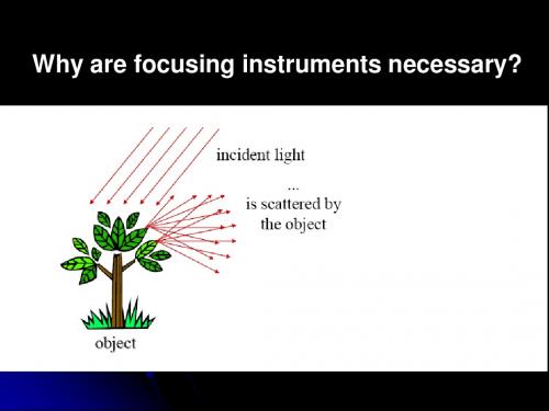
Why are focusing instruments necessary?
Refraction at curved surface
Imaging In order to image S at location P, the time it takes for each and every portion of a wavefront leaving S to converge at point P must be identical. So:
which followed with
n1 n2 1 n2 S i n1 S0 ( ) SM 2 MS ' R MS ' SM
Refraction at curved surface
Discussion Sign convention for spherical refraction surfaces and thin lenses
Refraction at curved surface
Fermat’s Principle maintains that the optical path length (OPLSS’) will be stationary (实际上,物与像之间根据费马原 理具有等光程性), i.e.:
南开大学光学工程内部课件Sep 28th
The objective lens has a short focal length, ƒo<1 cm The ocular lens (eyepiece) has a focal length, ƒe, of several cm L>> ƒo and ƒe
Compound Microscope
The image seen by the eye, I2, is virtual, inverted and very much enlarged
The magnification of the microscope is the product of the magnifications of the objective and the ocular lens
Normal
vision has a far point of infinity
Farsightedness
Also called hyperopia The image focuses behind the retina Can usually see far away objects clearly, but not nearby objects
m o
angle with lens angle without lens
Simple Magnifier
The angular magnification is at a maximum when the image formed by the lens is at the near point of the eye
Presbyopia and Astigmatism
Diopters
南开大学光子学课程讲义2-2-3-QuantumOptics
Uncertainties in Coherent States
Expectation values in coherent states
x
α
2 = Re α mω
2
p
α
2
= 2mω Im α
α
∆x
α
= 2mω
∆p = 2
∆p
mω = 2
Uncertainty product:
Independent of α
光子学基础 -2
Quantum Theory of Light
光量子理论
Quantum Optics
—— 量子光学
Introduction
量子光学是研究光场的量子统 计特性和光场与物质相互作用的学 科。
Outline
光子相干态(Coherent State) 光压缩态(Squeezed States of Light) 光量子纠缠态(Entanglement State)
unitary
0
Roy Glauber
a α =α α
any complex number
note: 0 is a coherent state
2005 Nobel Physics Prize!
烛光与激光 哪里不同?
用颜色, 能量, 准直性… 不能区别烛光与激光
烛光 (n )n n n n 1 n (1 n )
G. Breitenbach, S. Schiller, and J. Mlynek, "Measurement of the quantum states of squeezed light", Nature, 387, 471 (1997)
大学光学经典课件L1_绪论精品文档48页
在不同I 媒2 c n 质0 T 中0 T 有E 0 2 ( :1 II12c o s( nn2 21( EE002212t)))d t 2 c n0E 0 2
在相同介质中有:I nE02
4)相对光强:
I E02
注意:
光强是一个平均值
I
S
n
2c0
E02
5)光强定义为一个平均值的原因
响应时间:能够被感知或被记录所需的最短时间 人眼的响应时间:t0.1s 最好的仪器的响应时间大约: 109s 光波的振动周期:T1015s
学好光学课的重要意义
当今科研前沿的热门学科 光学课程是众多光学方面课程的基础启蒙课程
如:激光原理与技术,量子光学,信息学光纤 光学,集成光学,光谱学,光子开关术全息光 存储技术,光纤通信技术原理,非线性光学, 晶体光学,原子光学,光电信号检测技术等
光学课的特点
内容新:中学学得不多,光学发展很快,新 内容不断涌现
nc/
故
S 0 nE2 n E2
0
c0
真空中电磁波的波动方程: EE0cos(t)
可得:E 2 E 0 2 c o s 2 (t) 1 2 E 0 2 ( 1 c o s (2 (t)))
I S T 10 T c n 0E 2 d t T 10 T c n 0E 0 2c o s 2 (t)d t
tT
人眼和接收器只能感知光波的平均能流密度 有实际意义的是光波的平均能流
三、光 谱
1)单色光:仅有单一波长的光叫单色光,否则 是非单色光。
2)谱密度: d I~d i() dI
d
3)光谱:谱密度随波长变化的分布曲线
I
d
I
i()d
0
南开大学光学工程内部课件Oct 28th
Need Q ~ 105 or greater Led to super mirrors
polished to Angstroms ion beam machining polished to ~ 100 nanometers limited by grit size
Laser gyro developed for aircraft
tCCW = 8R 2c R
Travel time cw
tCW = 8R 2c - R
Time difference
Dt 4 A c2
Number of fringes
DN = 4 A cl
Fringe shift ~ 4 % for 2 rev/sec
Laser gyro
Interferometers
Interferometer
What is interferometer?
Interferometer is the optical setup which split incident light into two beams and then recombines them to create an interference fringe.
N=2L/ l =2L/ l
Phase change (in terms of wavelengths):
DN=Nm - N=2Ln/l- 2L/l= 2L/l (n-1)
The Michelson-Morley Experiment
1881
White light fringes
Adjust the mirrors to make the two path has the same path length, one can see white light fringes.
南开大学光学工程内部课件Nov 9th
Its reduced form is
E bc(
sin
)(
sin N
)e
i [t kR ( N 1 ) ]
The flux-density distribution function is
I ( ) I 0 (
sin
) (
2
sin N
)
2
Fraunhofer Diffraction
Fraunhofer Diffraction
The Double Slit
Two long slits of width b and center-to-center separation a
Fraunhofer Diffraction
Analysis Each aperture, by itself, would generate the same single-slit diffraction pattern on the screen . At any point on , the contribution from the two slits overlap and each must be equal in amplitude and different in phase. The density distribution should be a combination of a rapidly varying double-slit interference system, modulated by a singleslit diffraction pattern.
I ( ) / I ( 0) 1.0 0.047 0.017 0.008 ......
- 1、下载文档前请自行甄别文档内容的完整性,平台不提供额外的编辑、内容补充、找答案等附加服务。
- 2、"仅部分预览"的文档,不可在线预览部分如存在完整性等问题,可反馈申请退款(可完整预览的文档不适用该条件!)。
- 3、如文档侵犯您的权益,请联系客服反馈,我们会尽快为您处理(人工客服工作时间:9:00-18:30)。
E1 (r , t ) E01 exp i(k1 r t 1 ) E2 (r , t ) E02 exp i(k2 r t 2 ).
Two plane waves meet at P
Superposition of two beams
The transmitted light is incident onto a screen containing two narrow slits
Young’s Double Slit Experiment
The symmetric narrow slits, S1 and S2 act as the two light sources The waves from the two slits come from the same source S0 and therefore are always in phase.
m
= 0, ±1, ±2, …
Interference Equations
Y:measured vertically from the zeroth order maximum Assumptions
L >>d,
d >>λ
y =LtanθLsinθ
I I1 I 2 2 I1I 2 cos(kd sin ) I1 I 2 2 I1I 2 cos(kdy / L)
Other Coherent Sources
Currently, it is much more common to use a laser as a coherent source The laser produces an intense, coherent,
monochromatic parallel beam over a width of several millimeters
Light from a monochromatic source goes through a narrow slit. The narrow width of the silt make sure transmitted light comes from a tiny region of the source which is coherent.
Therefore, they arrive in phase
Interference Patterns
The upper wave has to travel farther than the lower wave The upper wave travels one wavelength farther
d 7 /(n 1) 6.6 m
Lloyd’s Mirror
Produce an interference pattern with a single light source Wave reach point P either by a direct path or by reflection
P
Obviously,
2 * * * I E E E ( E1 E2 ) ( E1 E2 ) * * * * E1 E1 E2 E2 E1 E2 E2 E1 2 2 * E1 E2 E1 E2 c.c. I1 I 2 I inter
Iinter * E1 Βιβλιοθήκη E2 c.c.I1 E
2 1
,
I2 E
2 2
Interference Pattern
I I1 I 2 2 I1I 2 cos cos
where presents the crossing angle between the linear polarization directions of the two beams, and
k1 r 1 k2 r 2 .
parallel
I I1 I 2 2 I1I 2 cos
Relation between Polarization Directions
perpendicular
I I1 I 2
Coherence Conditions for Interference
Interference Equations
When total destructive interference occurs, a dark fringe is observed
This needs a path difference of an odd half wavelength δ = d sin θdark = (m + ½ ) λ
Two beam interference
Superposition of two beams
P
Assume the observation point P is far enough away from the sources so that the wavefronts at P can be regarded as planes. And we limit our discussion to linearly polarized waves.
In order to get stable intensity-modulated interference pattern by using two beams, two conditions must be satisfied
The two waves must maintain a constant phase with respect to each other, i.e. have the same frequency and constant initial phase The two electric fields have the non-zero projective components onto each other, i.e. the polarization directions cannot be perpendicular to each other
This is destructive interference
A dark fringe occurs
Young’s Experiment (Double-Slit Interference)
Interference Equations
The path difference, δ, is found from the tan triangle Optical Path Differenceδ = L = r2 – r1 = d sin
The reflected ray can be treated as a ray from the image S’ below the mirror
Interference Pattern from Lloyd’s Mirror
Young’s Double Slit Experiment
In 1801, Thomas Young demonstrated for the first time interference of light The coherent sources was gotten through:
mica, thickness d
1
Phase with meca
1 k ' d 2 nd /
Phase without meca
d
2
2 kd 2 d /
air, thickness d
2 d (n 1) / 7 (2 )
The mica thickness is :
Young’s Double Slit Experiment provides a method for measuring wavelength of the light
This experiment gave the wave model of light a great deal of credibility
Laser pointer
Young’s double-slit interference
Side view of the interference field
Interference Patterns
Constructive interference occurs at the center point The two waves travel the same distance
Interference Equations
This assumes the paths are parallel Not exactly, but a very good approximation (L>>d)
Interference Equations
I I1 I 2 2 I1I 2 cos(k ) I1 I 2 2 I1I 2 cos(kd sin )
For a bright fringe interference happens
where
total
constructive
2m k m
m = 0, ±1, ±2, … m is called the order number
When When