最新地质岩土英文文献翻译_冶金矿山地质_工程科技_专业资料
土木工程岩土外文翻译
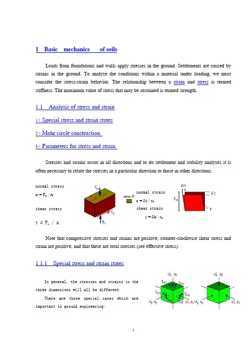
1 Basic mechanics of soilsLoads from foundations and walls apply stresses in the ground. Settlements are caused by strains in the ground. To analyze the conditions within a material under loading, we must consider the stress-strain behavior. The relationship between a strain and stress is termed stiffness. The maximum value of stress that may be sustained is termed strength.1.1 Analysis of stress and strain1)Special stress and strain states2)Mohr circle construction3)Parameters for stress and strainStresses and strains occur in all directions and to do settlement and stability analyses it is often necessary to relate the stresses in a particular direction to those in other directions.normal stress σ = F n / Ashear stressτ = F s/ A normal strain ε = δz / z oshear strainγ = δh / z oNote that compressive stresses and strains are positive, counter-clockwise shear stress and strain are positive, and that these are total stresses (see effective stress).1.1.1 Special stress and strain statesIn general, the stresses and strains in the three dimensions will all be different.There are three special cases which are important in ground engineering:General case princpal stressesAxially symmetric or triaxial statesStresses and strains in two dorections are equal.σ'x = σ'y and εx = εyRelevant to conditions near relatively small foundations,piles, anchors and other concentrated load s.P lane strain:Strain in one direction = 0εy = 0Relevant to conditions near long foundations,embankments, retaining walls and other long structures.One-dimensional compression:Strain in two directions = 0εx = εy = 0Relevant to conditions below wide foundations orrelatively thin compressible soil layers.Uniaxial compressionσ'x = σ'y = 0This is an artifical case which is only possible for soil isthere are negative pore water pressures.1.1.2 Mohr circle constructionrelate to a particular plane within an element of soil. Ingeneral, the stresses on another plane will be different.To visualise the stresses on all the possible planes,a graph called the Mohr circle is drawn by plotting a(normal stress, shear stress) point for a plane at everypossible angle.There are special planes on which the shearstress is zero (i.e. the circle crosses the normal stressaxis), and the state of stress (i.e. the circle) can be described by the normal stresses acting on these planes; these are called the principal stresses '1 and '3 .1.1.3 Parameters for stress and strainIn common soil tests, cylindrical samples are used in which the axial and radial stresses and strains are principal stresses and strains. For analysis of test data, and to develop soil mechanics theories, it is usual to combine these into mean (or normal) components which influence volume changes, and deviator (or shearing) components which influence shape changes.In the Mohr circle construction t' is the radius of the circle and s' defines its centre. Note: Total and effective stresses are related to pore pressure u:p' = p - u s' = s - u q' = q t' = t1.2 StrengthThe shear strength of a material is most simply described as the maximum shear stress it can sustain: When the shear stress is incre ased, the shear strain increases; there will be a limiting condition at which the shear strain becomes very large and the material fails; the shear stress f is then the shear strength of the material. The simple type of failure shown here is associatedwith ductile or plastic materials. If the material is brittle (like a piece of chalk), the failure may be sudden and catastrophic with loss of strength after failure.1.2.1 Types of failureMaterials can fail under different loading conditions. In each case, however, failure is associated with the limiting radius of the Mohr circle, i.e. the maximum shear stress. The following common examples are shown in terms of total stresses:ShearingShear strength = τfσnf = normal stress at failureUniaxial extensionTensile strength σtf = 2τfUniaxial compressionCompressive strength σcf = 2τfNote:Water has no strength f = 0.Hence vertical and horizontal stresses are equal and the Mohr circle becomes a point.1.2.2 Strength criteriaA strength criterion is a formula which relates the strength of a material to some other parameters: these are material parameters and may include other stresses.For soils there are three important strength criteria: the correct criterion depends on the nature of the soil and on whether the loading is drained or undrained.In General, course grained soils will "drain" very quickly (in engineering terms) following loading. Thefore development of excess pore pressure will not occur; volume change associated with increments of effective stress will control the behaviour and the Mohr-Coulomb criteria will be valid.Fine grained saturated soils will respond to loading initially by generating e xcess pore water pressures and remaining at constant volume. At this stage the Tresca criteria, which uses total stress to represent undrained behaviour, should be used. This is the short term or immediate loading response. Once the pore pressure has dissapated, after a certain time, the effective stresses have incresed and the Mohr-Coulomb criterion will describe the strength mobilised. This is the long term loading response.1.2.2.1 Tresca criterionThe strength is independent of the normal stress since the response to loading simple increases the pore water pressure and not theeffective stress.The shear strength f is a materialparameter which is known as the undrained shearstrength su.τf = (σa - σr) = constant1.2.2.2 Mohr-Coulomb (c'=0) criterionThe strength increases linearly with increasingnormal stress and is zero when the normal stress is zero.'f = 'n tan '' is the angle of frictionIn the Mohr-Coulomb criterion the materialparameter is the angle of friction and materials which meet this criterion are known as frictional. In soils, the Mohr-Coulomb criterion applies when the normal stress is an effective normal stress.1.2.2.3 Mohr-Coulomb (c'>0) criterionThe strength increases linearly with increasingnormal stress and is positive when the normal stress iszero.'f = c' + 'n tan '' is the angle of frictionc' is the 'cohesion' interceptIn soils, the Mohr-Coulomb criterion applies when the normal stress is an effective normal stress. In soils, the cohesion in the effective stress Mohr-Coulomb criterion is not the same as the cohesion (or undrained strength su) in the Tresca criterion.1.2.3Typical values of shear strengthOften the value of c' deduced from laboratory test results (in the shear testing apperatus) may appear to indicate some shar strength at ' = 0. i.e. the particles 'cohereing' together or are 'cemented' in some way. Often this is due to fitting a c', ' l ine to the experimental data and an 'apparent' cohesion may be deduced due to suction or dilatancy.1 土的基本性质来自地基和墙壁的荷载会在土地上产生应力。
最新地质岩土英文文献翻译_冶金矿山地质_工程科技_专业资料
地质岩土英文文献翻译_冶金矿山地质_工程科技_专业资料International Journal of Rock Mechanics and Mining SciencesAnalysis of geo-structural defects in flexural topplingfailureAbbas Majdi and Mehdi Amini AbstractThe in-situ rock structural weaknesses, referred to herein asgeo-structural defects, such as naturally induced micro-cracks, are extremely responsive to tensile stresses. Flexural toppling failure occurs by tensile stress caused by the moment due to the weight ofthe inclined superimposed cantilever-like rock columns. Hence, geo-structural defects that may naturally exist in rock columns are modeled by a series of cracks in maximum tensile stress plane. The magnitude and location of the maximum tensile stress in rock columns with potential flexural toppling failure are determined. Then, the minimum factor of safety for rock columns are computed by means of principles of solid and fracture mechanics, independently. Next, a new equation is proposed to determine the length of critical crack in such rock columns. It has been shown that if the length of natural crack is smaller than the length of critical crack, then the result based on solid mechanics approach is more appropriate; otherwise, the result obtained based on the principles of fracture mechanics is more acceptable. Subsequently, for stabilization of the prescribed rock slopes, some new analytical relationships are suggested for determination the length and diameter of the required fully grouted rock bolts. Finally, for quick design of rock slopes against flexural toppling failure, a graphical approach along with some design curves are presented by which an admissible inclination of such rock slopes and or length of all required fully grouted rock bolts are determined.In addition, a case study has been used for practical verification of the proposed approaches.Keywords Geo-structural defects, In-situ rock structural weaknesses, Critical crack length1.IntroductionRock masses are natural materials formed in the course ofmillions of years. Since during their formation and afterwards, they have been subjected to high variable pressures both vertically and horizontally, usually, they are not continuous, and contain numerous cracks and fractures. The exerted pressures, sometimes, produce joint sets. Since these pressures sometimes may not be sufficiently high to create separate joint sets in rock masses, they can produce micro joints and micro-cracks. However, the results cannot be considered as independent joint sets. Although the effects of these micro-cracksare not that pronounced compared with large size joint sets, yet they may cause a drastic change of in-situ geomechanical properties ofrock masses. Also, in many instances, due to dissolution of in-situ rock masses, minute bubble-like cavities, etc., are produced, which cause a severe reduction of in-situ tensile strength. Therefore, one should not replace this in-situ strength by that obtained in the laboratory. On the other hand, measuring the in-situ rock tensile strength due to the interaction of complex parameters is impractical. Hence, an appropriate approach for estimation of the tensile strength should be sought. In this paper, by means of principles of solid and fracture mechanics, a new approach for determination of the effect of geo-structural defects on flexural toppling failure is proposed.2. Effect of geo-structural defects on flexural toppling failure2.1. Critical section of the flexural toppling failureAs mentioned earlier, Majdi and Amini [10] and Amini et al. [11] have proved that the accurate factor of safety is equal to that calculated for a series of inclined rock columns, which, by analogy, is equivalent to the superimposed inclined cantilever beams as shown in Fig. 3. According to the equations of limit equilibrium, the moment M and the shearing force V existing in various cross-sectional areas in the beams can be calculated as follows:(5)( 6)Since the superimposed inclined rock columns are subjected to uniformly distributed loads caused by their own weight, hence, the maximum shearing force and moment exist at the v ery fixed end, that is, at x=Ψ:(7)(8)If the magnitude of Ψ from Eq. (1) is substituted into Eqs. (7) and (8), then the magnitudes of shearing force and the maximum moment of equivalent beam for rock slopes are computed as follows:(9)(10)where C is a dimensionless geometrical parameter that is related to the inclinations of the rock slope, the total failure plane and the dip of the rock discontinuities that existin rock masses, and can be determined by means of curves shown in Fig.Mmax and Vmax will produce the normal (tensile and compressive) and the shear stresses in critical cross-sectional area, respectively. However, the combined effect of them will cause rock columns to fail. It is well understood that the rocks are very susceptible to tensile stresses, and the effect of maximum shearing force is also negligible compared with the effect of tensile stress. Thus, for the purpose of the ultimate stability, structural defects reduce the cross-sectional area of load bearing capacity of the rock columns and, consequently, increase the stress concentration in neighboring solid areas. Thus, the in-situ tensile strength of the rock columns, the shearing effect might be neglected and only the tensile stress caused due to maximum bending stress could be used.2.2. Analysis of geo-structural defectsDetermination of the quantitative effect of geo-structural defects in rock masses can be investigated on the basis of the following two approaches.2.2.1. Solid mechanics approachIn this method, which is, indeed, an old approach, the loads from the weak areas are removed and likewise will be transferred to the neighboring solid areas. Therefore, the solid areas of the rock columns, due to overloading and high stress concentration, will eventually encounter with the premature failure. In this paper, for analysis of the geo-structural defects in flexural toppling failure, a set of cracks in critical cross-sectional area has been modeled as shown in Fig. 5. By employing Eq. (9) and assuming that the loads from weak areas are transferred to the solid areas with higher load bearing capacity (Fig. 6), the maximum stresses could be computed by the following equation (see Appendix A for more details):(11)Hence, with regard to Eq. (11), for determination of the factor of safety against flexural toppling failure in open excavations and underground openings including geo-structural defects the following equation is suggested:(12)From Eq. (12) it can be inferred that the factor of safety against flexural toppling failure obtained on the basis of principles of solid mechanics is irrelevant to the length of geo-structuraldefects or the crack length, directly. However, it is related to the dimensionless parameter “joint persistence”, k, as it was defined earlier in this paper. Fig. 2 represents the effect of parameter k on the critical height of the rock slope. This figure also shows the=1) with a potential of limiting equilibrium of the rock mass (Fsflexural toppling failure.Fig. 2. Determination of the critical height of rock slopes with a potential of flexural toppling failure on the basis of principles of solid mechanics.2.2.2. Fracture mechanics approachGriffith in 1924 [13], by performing comprehensive laboratory tests on the glasses, concluded that fracture of brittle materials is due to high stress concentrations produced on the crack tips which causes the cracks to extend (Fig. 3). Williams in 1952 and 1957 and Irwin in 1957 had proposed some relations by which the stress around the single ended crack tips subjected to tensile loading at infinite is determined [14], [15] and [16]. They introduced a new factor in their equations called the “stress intensity factor” whichindicates the stress condition at the crack tips. Therefore if this factor could be determined quantitatively in laboratorial, then, the factor of safety corresponding to the failure criterion based on principles of fracture mechanics might be computed.Fig. 3. Stress concentration at the tip of a single ended crack under tensile loading Similarly, the geo-structural defects exist in rock columns with a potential of flexural toppling failure could be modeled. As it was mentioned earlier in this paper, cracks could be modeled in a conservative approach such that the location of maximum tensile stress at presumed failure plane to be considered as the cracks locations (Fig. 3). If the existing geo-structural defects in a rock mass, are modeled with a series cracks in the total failure plane, then by means of principles of fracture mechanics, an equation for determination of the factor of safety against flexural toppling failure could be proposed as follows:(13)where KIC is the critical stress intensity factor. Eq. (13) clarifies that the factor of safety against flexural toppling failure derived based on the method of fracture mechanics is directly related to both the “joint persistence” and the “length of cracks”. As such the length of cracks existing in the rock columns plays important roles in stress analysis. Fig. 10 shows the influence of the crack length on the critical height of rock slopes. This figure represents the limiting equilibrium of the rock mass with the potential of flexural toppling failure. As it can be seen, an increase of the crack length causes a decrease in the critical height of the rock slopes. In contrast to the principles of solid mechanics, Eq. (13) or Fig. 4 indicates either the onset of failure of the rock columns or the inception of fracture development.Fig. 4. Determination of the critical height of rock slopes with a potential of flexural toppling failure on the basis of principle of fracture mechanics.3. Comparison of the results of the two approachesThe curves shown in Fig. represent Eqs. (12) and (13), respectively. The figures reflect the quantitative effect of the geo-structural defects on flexural toppling failure on the basis of principles of solid mechanics and fracture mechanics accordingly. For the sake of comparison, these equations are applied to one kind of rock mass (limestone) with the following physical and mechanical properties [16]: , , γ=20kN/m3, k=0.75.In any case studies, a safe and stable slope height can be determined by using Eqs. (12) and (13), independently. The two equations yield two different slope heights out of which the minimum height must be taken as the most acceptable one. By equating Eqs. (12) and (13), the following relation has been derived by which a crack length, in this paper called critical length of crack, can be computed:(14a)where ac is the half of the average critical length of the cracks. Since ac appears on both sides of Eq. (14a), the critical length of the crack could be computed by trial and error method. If the lengthof the crack is too small with respect to rock column thickness, then the ratio t/(t−2ac) is slightly greater than one. Therefore one may ignore the length of crack in denominator, and then this ratiobecomes 1. In this case Eq. (14a) reduces to the following equation, by which the critical length of the crack can be computed directly:(14b)It must be born in mind that Eq. (14b) leads to underestimatethe critical length of the crack compared with Eq. (14a). Therefore, for an appropriate determination of the quantitative effect of geo-structural defects in rock mass against flexural toppling failure,the following 3 conditions must be considered: (1) a=0; (2) a<ac; (3) a>ac.In case 1, there are no geo-structural defects in rock columns and so Eq. (3) will be used for flexural toppling analysis. In case 2, the lengths of geo-structural defects are smaller than the critical length of the crack. In this case failure of rock column occurs dueto tensile stresses for which Eq. (12), based on the principles of solid mechanics, should be used. In case 3, the lengths of existing geo-structural defects are greater than the critical length. In this case failure will occur due to growing cracks for which Eq. (13), based on the principles of fracture mechanics, should be used for the analysis.The results of Eqs. (12) and (13) for the limiting equilibrium both are shown in Fig. 11. For the sake of more accurate comparative studies the results of Eq. (3), which represents the rock columnswith no geo-structural defects are also shown in the same figure. Asit was mentioned earlier in this paper, an increase of the crack length has no direct effect on Eq. (12), which was derived based on principles of solid mechanics, whereas according to the principles of fracture mechanics, it causes to reduce the value of factor of safety. Therefore, for more in-depth comparison, the results of Eq. (13), for different values of the crack length, are also shown in Fig. As canbe seen from the figure, if the length of crack is less than the critical length (dotted curve shown in Fig. 11), failure is considered to follow the principles of solid mechanics which results the least slope height. However, if the length of crack increases beyond the critical length, the rock column fails due to high stress concentration at the crack tips according to the principles of fracture mechanics, which provides the least slope height. Hence, calculation of critical length of crack is of paramount importance.4. Estimation of stable rock slopes with a potential of flexural toppling failureIn rock slopes and trenches, except for the soil and rock fills, the heights are dictated by the natural topography. Hence, the desired slopes must be designed safely. In rock masses with the potential of flexural toppling failure, with regard to the length of the cracks extant in rock columns the slopes can be computed by Eqs.(3), (12), and (13) proposed in this paper. These equations caneasily be converted into a series of design curves for selection of the slopes to replace the lengthy manual computations as well. [Fig. 12], [Fig. 13], [Fig. 14] and [Fig. 15] show several such design curves with the potential of flexural topping failures. If the lengths of existing cracks in the rock columns are smaller than the critical length of the crack, one can use the design curves, obtained on the basis of principles of solid mechanics, shown in [Fig. 12] and [Fig. 13], for the rock slope design purpose. If the lengths of the cracks existing in rock columns are greater than the critical length of the crack, then the design curves derived based on principles of fracture mechanics and shown in [Fig. 14] and [Fig. 15] must be used for the slope design intention. In all, these design curves, with knowing the height of the rock slopes and the thickness of the rockcolumns, parameter (H2/t) is computed, and then from the designcurves the stable slope is calculated. It must be born in mind thatall the aforementioned design curves are valid for the equilibrium condition only, that is, when FS=1. Hence, the calculated slopes from the above design curves, for the final safe design purpose must be reduced based on the desired factor of safety. For example, if the information regarding to one particular rock slope are given [17]:k=0.25, φ=10°, σt=10MPa, γ=20kN/m3, δ=45°, H=100m, t=1 m, ac>a=0.1 m, and then according to Fig. 12 the design slope will be 63°, which represents the condition of equ ilibrium only. Hence, the final and safe slope can be taken any values less than the above mentioned one, which is solely dependent on the desired factor of safety.Fig. 5. Selection of critical slopes for rock columns with the potential of flexural toppling failure on the basis of principles of solid mechanics when k=0.25.Fig. 6. Selection of critical slopes for rock columns with the potential of flexural toppling failure based on principles of solid mechanics when k=0.75..Fig. 7. Selection of critical slopes for rock columns with the potential of flexural toppling failure based on principles of fracture mechanics when k=0.25.Fig. 8. Selection of critical slopes for rock columns with the potential of flexural toppling failure based on principles of fracture mechanics when k=0.75.5. Stabilization of the rock mass with the potential of flexural toppling failureIn flexural toppling failure, rock columns slide over each other so that the tensile loading induced due to their self-weighting grounds causes the existing cracks to grow and thus failure occurs. Hence, if these slides, somehow, are prevented then the expected instability will be reduced significantly. Therefore, employing fully grouted rock bolts, as a useful tool, is great assistance in increasing the degree of stability of the rock columns as shown in Fig. 16 [5] and [6]. However, care must be taken into account that employing fully grouted rock bolts is not the only approach to stabilize the rock mass with potential of flexural toppling failure. Therefore, depending up on the case, combined methods such as decreasing the slope inclination, grouting, anchoring, retaining walls, etc., may even have more effective application than fullygrouted rock bolts alone. In this paper a method has been presentedto determine the specification of fully grouted rock bolts tostabilize such a rock mass. It is important to mention that Eqs. (15), (16), (17), (18), (19) and (20) proposed in this paper may also be used as guidelines to assist practitioners and engineers to definethe specifications of the desired fully grouted rock bolts to be used for stabilization of the rock mass with potential of flexuraltoppling failure. Hence, the finalized specifications must also be checked by engineering judgments then to be applied to rock masses. For determination of the required length of rock bolts for the stabilization of the rock columns against flexural toppling failure the equations given in previous sections can be used. In Eqs. (12)and (13), if the factor of safety is replaced by an allowable value, then the calculated parameter t will indicate the thickness of the combined rock columns which will be equal to the safe length of the rock bolts. Therefore, the required length of the fully grouted rock bolts can be determined via the following equations which have been proposed in this paper, based on the following cases.Fig. 9. Stabilization of rock columns with potential of flexural toppling failure withfully grouted rock bolts.Case 1: principles of solid mechanics for the condition when (a<a c):(15)Case 2: principles of fracture mechanics for the condition when(a>a c):(16)Where FSS is the allowable factor of safety, T is the length of the fully grouted rock bolts, and Ω is the angle between rock bolt longitudinal axis and the line of normal to the discontinuities of rock slope.Eqs. (15) and (16) can be converted into some design curves as shown in Fig. In some cases, one single bolt with a length T may not guarantee the stability of the rock columns against flexural toppling failure since it may pass through total failure plane. In such a case, the rock columns can be reinforced in a stepwise manner so that the thickness of the sewn rock columns becomes equal to T [11].Eq. (17) represents the shear force that exists at any cross-sectional area of the rock bolts. Therefore, both shear force and shear stress at any cross-sectional area can be calculated by the following proposed equations:(17)(18)where V is the longitudinal shear force function, τ is theshear stress function, and Q(y) is the first moment of inertia.According to the equations of equilibrium, in each element of a beam, at any cross-sectional area the shear stresses are equal tothat exist in the corresponding longitudinal section [18]. Hence, the total shear force S in the longitudinal section of the beam can be calculated as follows:The inserted shear force in the cross-sectional area of the rock bolt is equal to the total force exerted longitudinally as well. Therefore,the shear force exerted to the rock bolt's cross-section can be computed as follows:7. ConclusionsIn this paper, geo-structural defects existing in the in-situ rock columns with the potential of flexural toppling failure have been modeled with a series of central cracks. Thereafter on the basis of principles of both the solid and fracture mechanics some new equations have been proposed which can be used for stability analysis and the stabilization of such rock slopes. The final outcomes of this research are given as follows:1. Geo-structural defects play imperative roles in the stability of rock slopes, in particular, flexural toppling failure.2. The results obtained on the basis of principles of solid mechanics approach indicate that the length of cracks alone has no influence on the determination of factor of safety, whereas the value of joint persistence causes a considerable change in its value. On the other hand, the factor of safety obtained based on principles of fracture mechanics approach is strongly influenced by both the length of existing cracks in rock columns and joint persistence as well.3. The critical length of cracks represents the equality line of the results obtained from both approaches: solid mechanics and fracture mechanics.4. If the length of the crack is less than the critical length, failure is considered to follow the principles of solid mechanics. However, if the length of crack increases beyond the critical length, the rock column fails due to high stress concentration at the crack tips, according to the principles of fracture mechanics.5. The present proposed equations are also converted into some design graphs that can be used for ease of application and to reduce manual lengthy calculations for determining the critical height of rock slopes with the potential of flexural toppling failure.6. In this paper, on the basis of principles of both solid mechanics and fracture mechanics some equations are proposed to determine the safe length and the diameter of the fully grouted rock bolts for stabilization of rock slopes with the potential of flexural toppling failure.7. For simplicity of computations, some design graphs for determination of the length of the fully grouted rock bolts for stabilization of rock slopes with the potential of flexural toppling failure are also presented.8. Slope stability analysis of the Galandrood mine shows the new approach is well suited for the analysis of flexural toppling failure.国际岩石力学与工程学报地质结构缺陷对弯曲倾倒破坏的影响作者:Abbas Majdi and Mehdi Amini摘要原位岩石弱点,在此统称为地质结构缺陷,如自然诱发的微裂纹,对拉应力有很大影响。
毕业论文(设计)文献翻译(地质工程方面)-中英文对照

Formation Mechanism and Distribution of Paleogene-Neogene Stratigraphic Reservoirs in Jiyang DepressionAbstractDuring Paleogene-Neogene period, multiple scale unconformities had been formed in Jiyang depression, which provided favorable conditions for stratigraphic reservoirs. In recent years, various Paleogene-Neogene stratigraphic reservoirs in Jiyang depression have been found, and proved reserves were rising significantly, which fully showed a great exploration potential for this kind of reservoirs. But the practice of exploration in recent years indicated that the unconformities carrier system and its ability of sealing, petroleum migration and its accumulation model, distribution of stratigraphic reservoirs are uncertain, which deeply restrict the exploration degree of stratigraphic reservoirs in Jiyang depression.Based on the analysis of a large number of exploration wells and seismic data for Typical reservoirs, the paper analyses unconformities construct and its effect to generation in the Paleogene—Neogene, and summarize the distribution pattern of stratigraphic reservoirs based on petroleum mechanism and accumulation model. Finally, a highly quantitative prediction modclof height of pools in stratigraphic reservoirs was established, the research results effectively guided the explorationPra- ctice of stratigraphic reservoir .There are four macro unconformity types of Paleogene—Neogene formation which including truncation-overlap, truncation·paral lel, parallel—overlap and paralel unconformity in Jiyang depression.Besides truncation-overlap unconformity lies in slopes of depression, and parallel unconformity developed inside of depression,another two types lie in local areas. Unconformity can be developed vertically three-layer structure which including unconformity roof rock, weathered clay layer and semi-weathered rock. It also Can be two—layer structure if without weathered clay layer.And part of semi—weather rock Can be form a hard shell accuse of its filling process during the laterstage.Geological characteristic of the structure layer of unconformity is different in lithology,mineralogy, element geochemistry and weather degree index. Based on optimal partition of sequential number and principal component analysis, logging quantification recognition method about unconformity structure layers were established, on which effective identification of unconformitystnlcture layers can bu achieved in the case of no rock core. The formation of various unconformity structure types isrelated to many factors such as, parent rock lithology, interval of deposition hiatus, palaeotopography,and preservation conditions, which aretogether to control spatial distributions of unconformity structure types .Macro styles and its vertical structure of unconformity can be effected as a blocking, reservoir, trap or carrier system.Blocking affection to fluid depends on weathered clay layer,hard shell of semi-weathered rock and mudstone. So petroleum migration and accumulation units is relatively independence above and belowunconformity if structure layers mentioned above existed. Reservoir affection is due to permeable rock, including roof sandstone .Semi-weathered sandstone, semi-weathered carbonate rock, semi—weathered igneous rock and semi-weathered metamorphic. Trap—controlling affection related to macro unconformity type and its juxtapose to permeability and impermeability rock above and below unconformity. It is easy to develop stratigraphy traps where the permeability and impermeability beds juxtapose in a truncation-overlap unconformity, where up permeability and down impermeability in parallel-overlap unconformity, and down permeability and up impermeability beds juxtapose in a truncation-parallel. Transporting affection is owing to lateral continuity of permeable rock of unconformity. In a terrestrial rift basin, petroleum migration in transverse or vertical short distance in local area, and is not conducive to petroleum long distance along unconformity, because interbedding pattern of mudstone and sandstone is dominated, and its physical property of mudstone improved poorly .Because of the long distance from resource to trap, migration and accumulation procese is very complicated.. Accumulation process of Paleogene-Neogene stratigraphic traps can be summarized as following:allochthonous source rock , compound transportation , later period charging, buoyancy and pressure conversion driving for accumulation, and blocking by non-permeable layer of unconformity, Trap types and its distribution are controlled by unconformity structure styles. Petroleum distribution and its scale are controlled by generating ability of Source rock. Petroleum accumulation area is decided by positive tectonic units. If carrier systemexisted , oil column of stratigraphic reservoirs is effected by four mainfactors which including generation expulsion quantity,migrating distance, dip angle and capillary resistance of carrier layer. Based on the analysis of single factor, the prediction model of height of oil columu through multi—factor regressions was established . Based on the model , the paper defruited favorable areas, which reserves in these areas exceed 1.5 x 1 08t .Research results of the paper combined closely with exploration practice, and according to previous research results,31 exploration wells had been drilled, which of them 17 wells were successfully from 2006 to 2009. There is accumulation proved reserves Was up to 2362x104t. and predict reserves was to 3684x104t .Keywords:Paleogene; Neogene; unconformity stratigraphie reservoirs; Fomation mechanism; distribution pattern; Jiyang depression1. Preface1.1 Foundationnd and signifacance of the topic1.1.1 Theme originThe theme is from the Sinopcc project:Forming and distribution of Tertiarystratigraphic reservoir of Jiyang depression .Theme number:P06012,deadline:2006-20081.1.2 Foundation and baekground of the themeThe tectonic events frequently occurred in Jiyang depression in paleogene-Neogene.It was favour of forming stratigraphic reservoir because of existence of several kinds of unconformity . Based on statistical data , beneficial area reservoired oil is about 9500km2, and the remaining resource is about 16x 108t in stratigraphic reservoirs of paleogene-Neogene stratas.Since 1980s,many overlap and unconformity reservoirs have been founded , explored reserves Was apparently increased with deep exploring. By the end of 2006 , explored resource had been up to 3.7×10⁸t which showed a large exploring potential.But , in fact , the research on stratigraphic reservoir is lack or Uttle , especially,Accumulation pattern and forecasting model of oil have not been studied systematically. For example , the successful ratio of exploration well testing which is the lowest in allkinds reservoirs Was only 35.7%about stratigraphie reservoir in paleogene-Neogene in Jiyang depression from2001-2005. The main loss reason for the overlap andunconformity reservoirs exploration is migration and trap of oil that is separently53.5%and 23.9%.Hereby , oil migration problem and trap validity are importantaspects for overlap and unconformity reservoir exploring.In short,it has three aspects as followed:(1)Shallow comprehension about conduction of ability of unconformity Research on unconformity in present indicated that it is not a simple surface three-dimension body which is important for migration of oil and gas.There has some deep knows about the basins in west China and the marine basins in China. The systematic theory is lack about structure characteristic which deeply affect accumulating oil and gas.(2)The remain uncertain migration and accumulation process of oil and gas about stratigraphic reservoir remain uncertain .Stratigraphic reservoir lay in edge of basin . So it is difficult to exactly hold accumulation regular of oil and gas because far distance traps and hydrocarbon resources make a complicated migration process.(3)Forecasting model of stratigraphic reservoir that could be used to guide explore is lack It is necessity to finely evaluate and explore stratigraphic reservoir along with degree of exploration. Mayor controlling factors remain uncertain in construction offorecasting model of stratigraphic reservoirs.1.1.3 Aim, sense and application value of themeThe study resolves the problem of statigraphic reservoir formation and distribution of Paleogene-Neogene in Jiyang depression. By analysis of uniformity structure, their affect on statigraphic reservoir formation will be identify; The accumulation model will be established through study on static geologic characteristic of statigraphic reservoir ; Forecast mode of oil extent will be achieved through research on oil extent and to predict oil quality.Research results Can not only be used to effectively guide statigraphic reservoirExploring, to raise drilling Success ratio, provide technical support for increasing oilproduction of the Sinopec, and also provide reference to statigraphic reservoir exploring of Bohai Bay area . Research will enormously deepen statigraphic reservoir accumulation regular and further enrich and improve subtle reservoir exploring theory .1.2 Research present at home and abroad1.2.1 Present research and development at home and abroadUnconformity reservoir is one of important exploring object since Levorsen proposed the concept of stratigraphic trap and then published paper on‘‘Stratigraphic oil field ” in 1 936.It turns into stratigraphic reservoir and lithology reservoir based on scholars deepenly research the Levorsen stratigraphic eservoir .Stratigraphic trap is formed as a result of the updip reservoir directly contigence with unconformity above. According to trap place, accurrence and barrier, stratigraphic oil pools is divided into overlap pool, unconformity barbered pool and ancient buried-hill pool .Unconformity reservoir research covers three main sections. One is unconformityand its effect on oil accumulating. The second section is developing paaem of stratigraphic trap. The third is mechanism of migrating and accumulating of oil and gas. Present studies mainly focus on the three sections above .(1)Unconformity and its effect on oil accumulationUnconformity is geology base and key element to form the overlap and unconformity barriered traps and relevant reservoir . In generally,research on overlap and unconformity barrier reservoirs is first unconformity research target.Oil geologists started to understand relationship between inconformity and oil and gas acumination in 1930s. Levorsen published the book of“geology of petroleumin'1954. The book entirely introduced definition and significance of unconformity and the relatiooships with oil accumulation .The research and application of unconformity were promoted by stratigraohy andrecent oil and gas accumulation theory,especially,thesequence stratigraohy pay a important role in predict of geological discontinuity .Pan zhongxiang[2’3]referred to unconformity importance for oil and gas accumulation in 1983. Unconformity is benefit to find petroleum because it is favour of oil and gas migration and accumulation. From 1990s, the research on unconformity and accumulation effect were also be done in Tarim basin, ordos basin, Bohai bay basin and Jungar basin, a important and innovation result were be achieved .Fuguang[4,5],Wu kongyou[l6,7]and Zhang jianlin[8]had noted that unconformity is not only a simple surface but also a special geology body, a migration and accumulation passageway of oil and gas. It is represent for tectonic movement, sea or lake suface change,and geologic alteration to earlier rocks.The inhomogeneity of alteration and later overlap make the a. rchitecture of unconformity. There ale three layers structure in a ideal unconformity: roof rock above unconformity, weathered clay horizon and semi-weathered rock.Unconformity formation is related to denudation time,climate, elevation, tectonic movement and lithology. Two layers structure layers were formed as the weathered clay horizon was lack. Liuhua[16], Suifenggui[17], etc. divided unconformity into four types sand/mud, sand/sand, mud/mud and mud/sand . According to lithologic deploy of unconformity. They refcred that the migrating and accumulating ability of unconformity are decided by lithologic deploy of unconformity .Panzhongxiang[2'3],Liuxiaohant[11],Zhangkeyin[12],Chenzhonghong[14],Hedengfa,Aihuaguo[19],Wuyajun[20],Chenjianping[22'23], Zhangjiguang[2l], John S[26]etc . had a deepresearch on unconformity and refered that unconformity has an apparent controllingeffect on oil and gas accumulation. In summery, five main aspects is included: charging reservoir, charging trap,charging migrating, charging accumulating anddestroying reservoir. Based on physical modeling of oil migration, Lv xiuzheng Bekele thought the oil migration is followed the rule “migration through thin bed”, namely, migration through prevailing passway, otherwise anywhere in a conformity .(2)Development regularity of stratigraphic trapsOverlapped and unconformity is premise of overlap and unconformity reservoirExiting. so, this kind reservoir developed based on overlapped and unconformity trap formation first.Chensizhong proposed four conditions for developing overlap and unconformity reservoirs in 1982 based on research on the characteristics of overlapped and unconformity reservoirs and its distribution patterns. First is that Multiple overlapped and unconformity reservoir formed as a result of Multiple unconformityies and overlaps.second is that oil avvumulation area is above and below unconformity nearby hydrocarbon source rock. Third is that Torque subsidence of dustpan depression cause wide rang of overlap and unconformity reservoir. Fourth is that favourable overlap and unconformity reservoir lies in anti-cycle litbofacies fold play. Tong xiao guang referred four main controlling factors in 1983. First is time, lithology, attitude and weathering degree of pre-Paleogene-Neogene base rocks. Second is structure of faulted depression and movement strength.Third is overlap distribution of overlap line and feature of overlap lay above unconformity. Fourth is distribution of unconformity surface, permeability of overburden rocks above unconformity. Hujianyi[1lreferred that unconformity is the base of forming overlap and unconformity barrier trap, but not all good trap exits bearby unconformity in 1 984 and 1 986. The basic condition of forming overlap and unconformity barrier trap are six elements:three lines and three surfaces. Three lines are lithologic wedging line, layer overlap line and intended zone contour line. Three surface are unconformity surface, adjacent rock surface of reservoir and fault surface. It exits kinds of trap types when six elementsarraies.People deeply know development regularity of overlap and unconformity trapwith sequence stratigraphy spring up. Zhangshanwen[31] refer that multi. type breakcontrol overlap and unconformity trap, base on researching sequence of Zhungaer basin, Bohaibay basin and Songliao basin in 2003. Lipilong[35-39] refer that tectonic and deposit control overlap and unconformity trap in 2003 and 2004. Tectonic movement cause basin up and down, formed large area exceed peel zone in edge of basin. It is benefit to form trap.Tectonic form nosing structures in basin. It is benefit to form traps, Deposit control reservoir and barrier layer forming. Yishiwei[42] propose that oil accumulation controlled three surface, lake extensive surface, unconformity surface and fault surface, according to Erlian basin, Jizhong depression overlap andinconformity reservoir characteristic. Overlap and unconformity reservoir distributionare controlled by truncation zone and overlap zone. Enriching is controlled by beneficial accumulating phase belt.(3)Oil and gas migration and accumulation mechanism of stratigraphic trapReservoir is resuk of oil and gas migrating and accumulating in long distance, due to stratigraphic trap far from hydracarbon source rock. It is controlled by migrating dynamic, passageway, path, distance and accumulation etc.Lipilong[35-39]refer that the most effective oil path is fault-sandfault-unconformity and fault-sand-unconformity compound transmit system for overlap and unconfortuity trap in 2003 and 2004.Lichunguang[44]refer that heavy crude is secondary gas/oil pool through unconformity path migrating and accumulating in unconformity accompany trap, based on researching feavy crude reservoir of Dongyingdepression in 1999. Zhangjiazhent and Wangyongshi[48]refer thatY'Lhezhuang reservoir mainly lie in 100m above old burial hill old layer reflect shaft in 2005. Capping formation and barrier formation control the accumulation of the area oil and gas. Better Capping formation and barrier formation, better oil accumulation Suifenggui[17]refers that it is key for stratigraphic trap accumulation that‘T-S’transmit system validity and ability consist of oil soures fault,sand and ubconformity in 2005 in Jiyang depression. Layer unconformity style affects the stratigraphy trap forming and oil and gas migration.Lvxiuxiang refer that migration in uncomformity is thin bed migration through oil migrating physical analog in 2000. Oil migrates along advantage path, but not unconformity surface.All in one, there are many researches and outcome about trap develop and oil/gas accumulation of land facies basin stratigraphy reservoir home and abroad. But trap forcast is difficult because stratigraphy lie in basin edge and changeable lithofacies.Accumulation regular known less than other type reservoir, especially how unconformity affect stratigraphic reservoir develop, accumulation process, model and distribution, because of long distance between trap and hydrocarbon ,complex migtation process.1.2.2 Developing tendencyOverlap and unconformity reservoir show more and more important position with development of un-anticlinal trap exploratory development and rising of degree of exploration of petroliferous basin.Survey showed that although large of reseach and probe,research of overlap and unconformity are limited at quality. But, the common understanding include following respects:(1)Evaluation of structure, carrier system and barrier abilityUnconformity is important to develop overlap and unconformitty barrier reservoir. Now research about unconformity focus on one angle. It is tendency that begins with contributing factor of unconformity, analysis structure, make definite forming characteristic, evaluate transmiting and barrier ability,analyze the relationship between unconformity and oil/gas reservoir. (2)Mayor controlling factors and developing regularity of overlap and unconformity reservoir.It is common understanding that key overlap and unconformity barrier trap formation in develop system in home and abroad. Based Oll many research, this type trap is controlled by reservoir, cap rock and crossrange barrier, especially their valid matching.However,there is not deep research on three elements on system and contributing because of exploration phase confinement.(3)Oil and gas migration mechanism and accumulation model of overlapped andstratigraphic reservoir.With long distance migration and accumulation, reservoir development relate toDynamic, fashion, path, distance, process, etc. Element. They limit the understandingabout oil migrating mechanism. It is tendency that based on quantification, combinating type dissect, establishing accumulating model, effectively guide unconformity reservoir exploration .1.3 Research content and technique route1.3.1 Research contentThe subject confh'm following three research contents in view of key problembased on research present and development tendency .(1)Characteristic and distribution ofunconformity architecturesBased on basin the evolution of basin structure and deposition, through structural geology and sedimentology, and combined lab analysis, geophysical interpretation and mathematical statistics, the geology characteristic of unconformity and mayor controlling factors were analysised to definite spatial distribution unconformity architectures .(2)Formation mechanism and accumulation model of stratigraphic reservoirBased on geology comprehensive research and mathematical statistics ofstatic-characteristic of stratigraphy reservoir and by analysis migration and accumulation.Process, the migration path, accumulation stage and accumulation dynamic mechanism were analyzed to evaluate unconformity affect on oil/gas accumulation in geological history .Based on above research, sum up stratigraphy reservoir accumulating mechanism of Paleogene-Neogene, establish accumulating model through positive and negative respects research .(3)Distribution paRem and predict of favorable area of stratigraphy reservoirAccording to accumulation process and model, sum up distribution of stratigraphy reservoir. Based on mathematics statistics and geology analysis, make definite main element and quantification token parameter of oilness altitude, probe quantification forcast model of oilness altitude of stratigraphy reservoir starting from oil/gas migrating and accumulation process .Based on research findings above, it mainly focus on forecasting of stratigraphicreservoir nearby unconformities between Paleogene—Neogene and pre—Paleogene, and between Neogene and Paleogene .1.3.2 Technique routeUsing for reference from outcome of predecessors, based on type characteristic and distribution of unconformity of Jiyang depression, keep layer unique feature and accumulation process dissecting loss trap analyze as key, make geology comprehensive research and mathematical statistics method, sum up accumulation process and model, sum up main element, establish quantification forcast model of trap oilness, evaluate benefit exploring area .Figl-1: Frame picture showing research technique route ofdistribution patternand formationof samigraphy reservoir in Paleogene and Neogene slratas in Jiyang depression济阳坳陷古近系一新近系地层油藏形成机制与分布规律摘要济阳坳陷古近系.新近系发育过程中,形成了多个规模不等的不整合,为地层油藏的发育提供了有利条件。
岩土工程中英文对照外文翻译文献
中英文对照外文翻译(文档含英文原文和中文翻译)原文:Safety Assurance for Challenging Geotechnical Civil Engineering Constructions in Urban AreasAbstractSafety is the most important aspect during design, construction and service time of any structure, especially for challenging projects like high-rise buildings and tunnels in urban areas. A high level design considering the soil-structure interaction, based on a qualified soil investigation is required for a safe and optimised design. Dueto the complexity of geotechnical constructions the safety assurance guaranteed by the 4-eye-principle is essential. The 4-eye-principle consists of an independent peer review by publicly certified experts combined with the observational method. The paper presents the fundamental aspects of safety assurance by the 4-eye-principle. The application is explained on several examples, as deep excavations, complex foundation systems for high-rise buildings and tunnel constructions in urban areas. The experiences made in the planning, design and construction phases are explained and for new inner urban projects recommendations are given.Key words: Natural Asset; Financial Value; Neural Network1.IntroductionA safety design and construction of challenging projects in urban areas is based on the following main aspects:Qualified experts for planning, design and construction;Interaction between architects, structural engineers and geotechnical engineers;Adequate soil investigation;Design of deep foundation systems using the FiniteElement-Method (FEM) in combination with enhanced in-situ load tests for calibrating the soil parameters used in the numerical simulations;Quality assurance by an independent peer review process and the observational method (4-eye-principle).These facts will be explained by large construction projects which are located in difficult soil and groundwater conditions.2.The 4-Eye-PrincipleThe basis for safety assurance is the 4-eye-principle. This 4-eye-principle is a process of an independent peer review as shown in Figure 1. It consists of 3 parts. The investor, the experts for planning and design and the construction company belong to the first division. Planning and design are done accordingto the requirements of the investor and all relevant documents to obtain the building permission are prepared. The building authorities are the second part and are responsible for the buildingpermission which is given to the investor. The thirddivision consists of the publicly certified experts.They are appointed by the building authorities but work as independent experts. They are responsible for the technical supervision of the planning, design and the construction.In order to achieve the license as a publicly certified expert for geotechnical engineering by the building authorities intensive studies of geotechnical engineering in university and large experiences in geotechnical engineering with special knowledge about the soil-structure interaction have to be proven.The independent peer review by publicly certified experts for geotechnical engineering makes sure that all information including the results of the soil investigation consisting of labor field tests and the boundary conditions defined for the geotechnical design are complete and correct.In the case of a defect or collapse the publicly certified expert for geotechnical engineering can be involved as an independent expert to find out the reasons for the defect or damage and to develop a concept for stabilization and reconstruction [1].For all difficult projects an independent peer review is essential for the successful realization of the project.3.Observational MethodThe observational method is practical to projects with difficult boundary conditions for verification of the design during the construction time and, if necessary, during service time. For example in the European Standard Eurocode 7 (EC 7) the effect and the boundary conditions of the observational method are defined.The application of the observational method is recommended for the following types of construction projects [2]:very complicated/complex projects;projects with a distinctive soil-structure-interaction,e.g. mixed shallow and deep foundations, retaining walls for deep excavations, Combined Pile-Raft Foundations (CPRFs);projects with a high and variable water pressure;complex interaction situations consisting of ground,excavation and neighbouring buildings and structures;projects with pore-water pressures reducing the stability;projects on slopes.The observational method is always a combination of the common geotechnical investigations before and during the construction phase together with the theoretical modeling and a plan of contingency actions(Figure 2). Only monitoring to ensure the stability and the service ability of the structure is not sufficient and,according to the standardization, not permitted for this purpose. Overall the observational method is an institutionalized controlling instrument to verify the soil and rock mechanical modeling [3,4].The identification of all potential failure mechanismsis essential for defining the measure concept. The concept has to be designed in that way that all these mechanisms can be observed. The measurements need to beof an adequate accuracy to allow the identification ocritical tendencies. The required accuracy as well as the boundary values need to be identified within the design phase of the observational method . Contingency actions needs to be planned in the design phase of the observational method and depend on the ductility of the systems.The observational method must not be seen as a potential alternative for a comprehensive soil investigation campaign. A comprehensive soil investigation campaignis in any way of essential importance. Additionally the observational method is a tool of quality assurance and allows the verification of the parameters and calculations applied in the design phase. The observational method helps to achieve an economic and save construction [5].4.In-Situ Load TestOn project and site related soil investigations with coredrillings and laboratory tests the soil parameters are determined. Laboratory tests are important and essential for the initial definition of soil mechanical properties of the soil layer, but usually not sufficient for an entire and realistic capture of the complex conditions, caused by theinteraction of subsoil and construction [6].In order to reliably determine the ultimate bearing capacity of piles, load tests need to be carried out [7]. Forpile load tests often very high counter weights or strong anchor systems are necessary. By using the Osterberg method high loads can be reached without install inganchors or counter weights. Hydraulic jacks induce the load in the pile using the pile itself partly as abutment.The results of the field tests allow a calibration of the numerical simulations.The principle scheme of pile load tests is shown in Figure 3.5.Examples for Engineering Practice5.1. Classic Pile Foundation for a High-Rise Building in Frankfurt Clay and LimestoneIn the downtown of Frankfurt am Main, Germany, on aconstruction site of 17,400 m2 the high-rise buildingproject “PalaisQuartier” has been realized (Figure 4). The construction was finished in 2010.The complex consists of several structures with a total of 180,000 m2 floor space, there of 60,000 m2 underground (Figure 5). The project includes the historic building “Thurn-und Taxis-Palais” whose facade has been preserved (Unit A). The office building (Unit B),which is the highest building of the project with a height of 136 m has 34 floors each with a floor space of 1340 m2. The hotel building (Unit C) has a height of 99 m with 24 upper floors. The retail area (Unit D)runs along the total length of the eastern part of the site and consists of eight upper floors with a total height of 43 m.The underground parking garage with five floors spans across the complete project area. With an 8 m high first sublevel, partially with mezzanine floor, and four more sub-levels the foundation depth results to 22 m below ground level. There by excavation bottom is at 80m above sea level (msl). A total of 302 foundation piles(diameter up to 1.86 m, length up to 27 m) reach down to depths of 53.2 m to 70.1 m. above sea level depending on the structural requirements.The pile head of the 543 retaining wall piles (diameter1.5 m, length up to 38 m)were located between 94.1 m and 99.6 m above sea level, the pile base was between 59.8 m and 73.4 m above sea level depending on the structural requirements. As shown in the sectional view(Figure 6), the upper part of the piles is in the Frankfurt Clay and the base of the piles is set in the rocky Frankfurt Limestone.Regarding the large number of piles and the high pile loads a pile load test has been carried out for optimization of the classic pile foundation. Osterberg-Cells(O-Cells) have been installed in two levels in order to assess the influence of pile shaft grouting on the limit skin friction of the piles in the Frankfurt Limestone(Figure 6). The test pile with a total length of 12.9 m and a diameter of 1.68 m consist of three segments and has been installed in the Frankfurt Limestone layer 31.7 m below ground level. The upper pile segment above the upper cell level and the middle pile segment between the two cell levels can be tested independently. In the first phase of the test the upper part was loaded by using the middle and the lower part as abutment. A limit of 24 MN could be reached (Figure 7). The upper segment was lifted about 1.5 cm, the settlement of the middle and lower part was 1.0 cm. The mobilized shaft friction was about 830 kN/m2.Subsequently the upper pile segment was uncoupled by discharging the upper cell level. In the second test phase the middle pile segment was loaded by using the lower segment as abutment. The limit load of the middle segment with shaft grouting was 27.5 MN (Figure 7).The skin friction was 1040 kN/m2, this means 24% higher than without shaft grouting. Based on the results of the pile load test using O-Cells the majority of the 290 foundation piles were made by applying shaft grouting. Due to pile load test the total length of was reduced significantly.5.2. CPRF for a High-Rise Building in Clay MarlIn the scope of the project Mirax Plaza in Kiev, Ukraine,2 high-rise buildings, each of them 192 m (46 storeys)high, a shopping and entertainment mall and an underground parking are under construction (Figure 8). The area of the project is about 294,000 m2 and cuts a 30 m high natural slope.The geotechnical investigations have been executed 70m deep. The soil conditions at the construction site are as follows: fill to a depth of 2 m to 3mquaternary silty sand and sandy silt with a thickness of 5 m to 10 m tertiary silt and sand (Charkow and Poltaw formation) with a thickness of 0 m to 24 m tertiary clayey silt and clay marl of the Kiev and But schak formation with a thickness of about 20 m tertiary fine sand of the But schak formation up to the investigation depthThe ground water level is in a depth of about 2 m below the ground surface. The soil conditions and a cross section of the project are shown in Figure 9.For verification of the shaft and base resistance of the deep foundation elements and for calibration of the numerical simulations pile load tests have been carried out on the construction yard. The piles had a diameter of 0.82 m and a length of about 10 m to 44 m. Using the results of the load tests the back analysis for verification of the FEM simulations was done. The soil properties in accordance with the results of the back analysis were partly 3 times higher than indicated in the geotechnical report. Figure 10 shows the results of the load test No. 2 and the numerical back analysis. Measurement and calculation show a good accordance.The obtained results of the pile load tests and of the executed back analysis were applied in 3-dimensionalFEM-simulations of the foundation for Tower A, taking advantage of the symmetry of the footprint of the building. The overall load of the Tower A is about 2200 MN and the area of the foundation about 2000 m2 (Figure11).The foundation design considers a CPRF with 64 barrettes with 33 m length and a cross section of 2.8 m × 0.8m. The raft of 3 m thickness is located in Kiev Clay Marl at about 10 m depth below the ground surface. The barrettes are penetrating the layer of Kiev Clay Marl reaching the Butschak Sands.The calculated loads on the barrettes were in the range of 22.1 MN to 44.5 MN. The load on the outer barrettes was about 41.2 MN to 44.5 MN which significantly exceeds the loads on the inner barrettes with the maximum value of 30.7 MN. This behavior is typical for a CPRF.The outer deep foundation elements take more loads because of their higher stiffness due to the higher volume of the activated soil. The CPRF coefficient is 0.88 =CPRF . Maximum settlements of about 12 cm werecalculated due to the settlement-relevant load of 85% of the total design load. The pressure under the foundation raft is calculated in the most areas not exceeding 200 kN/m2, at the raft edge the pressure reaches 400 kN/m2.The calculated base pressure of the outer barrettes has anaverage of 5100 kN/m2 and for inner barrettes an average of 4130 kN/m2. The mobilized shaft resistance increases with the depth reaching 180 kN/m2 for outer barrettes and 150 kN/m2 for inner barrettes.During the construction of Mirax Plaza the observational method according to EC 7 is applied. Especially the distribution of the loads between the barrettes and the raft is monitored. For this reason 3 earth pressure devices were installed under the raft and 2 barrettes (most loaded outer barrette and average loaded inner barrette) were instrumented over the length.In the scope of the project Mirax Plaza the new allowable shaft resistance and base resistance were defined for typical soil layers in Kiev. This unique experience will be used for the skyscrapers of new generation in Ukraine.The CPRF of the high-rise building project MiraxPlaza represents the first authorized CPRF in the Ukraine. Using the advanced optimization approaches and taking advantage of the positive effect of CPRF the number of barrettes could be reduced from 120 barrettes with 40 mlength to 64 barrettes with 33 m length. The foundation optimization leads to considerable decrease of the utilized resources (cement, aggregates, water, energy etc.)and cost savings of about 3.3 Million US$.译文:安全保证岩土公民发起挑战工程建设在城市地区摘要安全是最重要的方面在设计、施工和服务时间的任何结构,特别是对具有挑战性的项目,如高层建筑和隧道在城市地区。
地质与岩土工程专业英语论文tb
岩土工程英语作业姓名:汤彪学号:013621814102班级:0133018141SHORT COMMUNICATIONS ANALYTICAL METHOD FOR ANALYSIS OFSLOPE STABILITYJINGGANG CAOs AND MUSHARRAF M. ZAMAN*tSchool of Civil Engineering and Environmental Science,University of Oklahoma, Norman, OK 73019, U.S.A.SUMMARYAn analytical method is presented for analysis of slopestability involving cohesive and non-cohesive soils.Earthquakeeffects are considered in an approximate manner in terms ofseismic coe$cient-dependent forces. Two kinds of failure surfaces areconsidered in this study: a planar failure surface, and acircular failure surface. The proposed method can be viewed asan extension of the method of slices, but it provides a moreaccurate etreatment of the forces because they are representedin an integral form. The factor of safety is obtained by usingthe minimization technique rather than by a trial and errorapproach used commonly.The factors of safety obtained by the analytical method arefound to be in good agreement with those determined by the localminimum factor-of-safety, Bishop's, and the method of slices. Theproposed method is straightforward, easy to use, and lesstime-consuming in locating the most critical slip surface andcalculating the minimum factor of safety for a given slope.Copyright ( 1999) John Wiley & Sons, Ltd.Key words: analytical method; slope stability; cohesive andnon-cohesive soils; dynamic effect; planar failure surface;circular failure surface; minimization technique;factor-of-safety.INTRODUCTIONOne of the earliest analyses which is still used in manyapplications involving earth pressure was proposed by Coulomb in1773. His solution approach for earth pressures against retainingwalls used plane sliding surfaces, which was extended to analysis of slopes in 1820 by Francais. By about 1840, experience with cuttings and embankments for railways and canals in England and France began to show that many failure surfaces in clay were not plane, but signi"cantly curved. In 1916, curved failure surfaces were again reported from the failure of quay structures in Sweden. In analyzing these failures, cylindrical surfaces were used and the sliding soil mass was divided into a number of vertical slices. The procedure is still sometimes referred to as the Swedish method of slices. By mid-1950s further attention was given to the methods of analysis usingcircular and non-circular sliding surfaces . In recent years, numerical methods have also been used in the slope stability analysis with the unprecedented development of computer hardware and software. Optimization techniques were used by Nguyen,10 and Chen and Shao. While finite element analyses have great potential for modelling field conditions realistically, they usually require signi"cant e!ort and cost that may not be justi"ed in some cases.The practice of dividing a sliding mass into a number of slices is still in use, and it forms the basis of many modern analyses.1,9 However, most of these methods use the sums of the terms for all slices which make the calculations involved in slope stability analysis a repetitive and laborious process.Locating the slip surface having the lowest factor of safety is an important part of analyzing a slope stability problem. A number of computer techniques have been developed to automate as much of this process as possible. Most computer programs use systematic changes in the position of the center of the circle and the length of the radius to find the critical circle.Unless there are geological controls that constrain the slip surface to a noncircular shape, it can be assumed with a reasonablecertainty that the slip surface is circular.9 Spencer (1969) found that consideration of circular slip surfaces was as critical as logarithmic spiral slip surfaces for all practical purposes. Celestino and Duncan (1981), and Spencer (1981) found that, in analyses where the slip surface was allowed to take any shape, the critical slip surface found by the search was essentially circular. Chen (1970), Baker and Garber (1977), and Chen and Liu maintained that the critical slip surface is actually a log spiral. Chen and Liu12 developed semi-analytical solutions using variational calculus, for slope stability analysis with a logspiral failure surface in the coordinate system. Earthquake e!ects were approximated in terms of inertiaforces (vertical and horizontal) defined by the corresponding seismic coe$cients. Although this is one of the comprehensive and useful methods, use of /-coordinate system makes the solution procedure attainable but very complicated. Also, the solutions are obtained via numerical means at the end. Chen and Liu12 have listed many constraints, stemming from physical considerations that need to be taken into account when using their approach in analyzing a slope stability problem.The circular slip surfaces are employed for analysis of clayey slopes, within the framework of an analytical approach, in this study. The proposed method is more straightforward and simpler than that developed by Chen and Liu. Earthquake effects are included in the analysis in an approximate manner within the general framework of static loading. It is acknowledged that earthquake effects might be better modeled by including accumulated displacements in the analysis. The planar slip surfaces are employed for analysis of sandy slopes. A closed-form expression for the factor of safety is developed, which is diferent from that developed by Das.STABILITY ANALYSIS CONDITIONS AND SOIL STRENGTHThere are two broad classes of soils. In coarse-grained cohesionless sands and gravels, the shear strength is directly proportional to the stress level:''tan f τσθ= (1)where fτ is the shear stress at failure, /σ the effectivenormal stress at failure, and /θ the effective angle of shearing resistance of soil.In fine-grained clays and silty clays, the strength depends on changes in pore water pressures or pore water volumes which take place during shearing. Under undrained conditions, the shear strength cu is largely independent of pressure, that is u θ=0. When drainage is permitted, however, both &cohesive' and &frictional' components ''(,)c θ are observed. In this case the shear strength is given by(2)Consideration of the shear strengths of soils under drained and undrained conditions, and of the conditions that will control drainage in the field are important to include in analysis of slopes. Drained conditions are analyzed in terms of effective stresses, using values of ''(,)c θ determined from drained tests, or from undrained tests with pore pressure measurement. Performing drained triaxial tests on clays is frequently impractical because the required testing time can be too long. Direct shear tests or CU tests with pore pressure measurement are often used because the testing time is relatively shorter.Stability analysis involves solution of a problem involving force and/or moment equilibrium.The equilibrium problem can be formulated in terms of (1) total unit weights and boundary water pressure; or (2) buoyant unit weights and seepage forces. The first alternative is a better choice, because it is morestraightforward. Although it is possible, in principle, to usebuoyant unit weights and seepage forces, that procedure is fraught with conceptual diffculties.PLANAR FAILURE SURFACEFailure surfaces in homogeneous or layered non-homogeneous sandy slopes are essentially planar. In some important applications, planar slides may develop. This may happen in slope, where permeable soils such as sandy soil and gravel or some permeable soils with some cohesion yet whose shear strength is principally provided by friction exist. For cohesionless sandy soils, the planar failure surface may happen in slopes where strong planar discontinuities develop, for example in the soil beneath the ground surface in natural hillsides or in man-made cuttings.ααβ图平面破坏Figure 1 shows a typical planar failure slope. From an equilibrium consideration of the slide body ABC by a vertical resolution of forces, the vertical forces across the base of the slide body must equal to weight w. Earthquake effects may be approximated by including a horizontal acceleration kg which produces a horizontal force k= acting through the centroid of the body and neglecting vertical inertia.1 For a slice of unit thickness in the strike direction, the resolved forces of normaland tangential components N and ¹ can be written as(cos sin )N W k αα=-(3)(sin cos )T W k αα=+(4) where is the inclination of the failure surface and w is given by02(tan tan )(tan )(cot cot )2LW x x dx H x dx H γβαγαγαβ=-+-=-⎰⎰ (5) where γ is the unit weight of soil, H the height of slope, cot ,cot ,L H l H βαβ== is the inclination of the slope. Since the length of the slide surface AB is /sin cH α, the resisting force produced by cohesion is cH /sin a. The friction force produced by N is (cos sin )tan W k ααφ-. The total resisting or anti-sliding force is thus given by(cos sin )tan /sin R W k cH ααφα=-+(6)For stability, the downslope slide force ¹ must not exceed the resisting force R of the body. The factor of safety, F s , in the slope can be defined in terms of effective force by ratio R /T, that is1tan 2tan tan (sin cos )sin()s k c F k H k αφαγααβα-=+++- (7) It can be observed from equation (7) that F s is a function of a. Thus the minimum value of F s can be found using Powell's minimization technique18 from equation (7). Das reported a similar expression for F s with k =0, developed directly from equation (2) by assuming that /s f d F ττ=, where f τ is the averageshear strength of the soil, and d τ the average shear stressdeveloped along the potential failure surface.For cohesionless soils where c =0, the safety factor can bereadily written from equation (7) as 1tan tan tan s k F k αφα-=+ (8) It is obvious that the minimum value of F s occurs when a=b, and the failure becomes independent of slope height. For such cases (c=0 and k=0), the factors of safety obtainedfrom the proposed method and from Das are identical.CIRCULAR FAILURE SURFACESlides in medium-stif clays are often deep-seated, and failure takes place along curved surfaces which can be closely approximated in two dimensions by circular surfaces. Figure 2 shows a potential circular sliding surface AB in two dimensions with centre O and radius r . The first step in the analysis is to evaluate the sliding' or disturbing moment M s about the centre of thecircle O . This should include the self-weight w of the sliding mass, and other terms such as crest loadings from stockpiles or railways, and water pressures acting externally to the slope.Earthquake effects is approximated by including a horizontal acceleration kg which produces a horiazontal force k d=acting through the centroid of each slice and neglecting vertical inertia. When the soil above AB is just on the point of sliding, the average shearing resistance which is required along AB for limiting equilibrium is given by equation (2). The slide mass is divided into vertical slices, and a typical slice DEFG is shown. The self-weight of the slice is dW hdx γ=. The method assumes that the resultant forces Xl and Xr on DE and FG , respectively, are equal and opposite, and parallel to the base of the slice EF . It is realized that these assumptions are necessary to keep theanalytical solution of the slope stability problem addressed in this paper achievable and some of these assumptions would lead to restrictions in terms of applications (e.g.earth pressure on retaining walls). However, analytical solutions have a special usefulness in engineering practice, particularly in terms of obtaining approximate solutions. More rigorous methods, e.g. finite element technique, can then be used to pursue a detail solution. Bishop's rigorous method5 introduces a furthernumerical procedure to permit specialcation of interslice shear forces Xl and Xr . Since Xl and Xr are internal forces, ()l r X X -∑ must be zero for the whole section. Resolving prerpendicularly and parallel to EF , one getssin cos T hdx k hdx γαγα=+(9)cos csin N hdx k hdx γαγα=-(10)22arcsin ,x a r a b rα-==+ (11)The force N can produce a maximum shearing resistance when failure occurs:sec (cos sin )tan R cdx hdx k αγααφ=+-(12)The equations of lines AC , CB , and AB Y are given by y22123tan ,,()y x y h y b r x a β===---(13)The sums of the disturbing and resisting moments for all slices can be written as013230(sin cos )()(sin cos )()(sin cos )()ls l lL s c M r h k dx r y y k dx r y y k dx r I kI γααγααγααγ=+=-++-+=+⎰⎰⎰ (14) []02300232sec (cos sin )tan sec ()(cos sin )tan ()(cos sin )tan tan ()lr l l lL c s M r c h k dx r c dx r y y k dx r y y k dx r c r I kI αγααφαγααφγααφϕγφ=+-=+--+--=+-⎰⎰⎰⎰ (15)22cot ,()L H l a r b H β==+-- (16)arcsinarcsin l a a r r ϕ-=+ (17) 1323022()sin ()sin 1(cot )sec 23Ll s L I y y dx y y dxH a b H rααββ=-+-⎡⎤=+-⎢⎥⎣⎦⎰⎰ (18) 13230222222222()cos ()cos tan tan 2()()()623(tan )arcsin (tan )arcsin 221()arcsin()4()()26L l s L I y y dx y y dxb r b r L a r L a r r r L a r a a H a b r r r l a b H r l ab l a H a r r ααββββ=-+-⎡⎤=-+---++⎣⎦-⎛⎫⎛⎫+-+- ⎪ ⎪⎝⎭⎝⎭-⎡⎤--+-+--⎣⎦⎰⎰ (19) The safety factor for this case is usually expressed as the ratio of the maximum available resisting moment to the disturbing moment, that istan ()()c s r s s s c c r I kI M F M I kI ϕγφγ+-==+ (20) When the slope inclination exceeds 543, all failures emerge at the toe of the slope, which is called t oe failure , as shown in Figure 2. However, when the slope height H is relatively large compared with the undrained shear strength or when a hard stratum is under the top of the slope of clayey soil with 03φ<, the slide emerges from the face of the slope, which is called Face failure , as shown in Figure 3. For Face failure , the safety factor F s is the same as ¹oe failure 1s using 0()Hh - instead of H .For flatter slopes, failure is deep-seated and extends to the hard stratum forming the base of the clay layer, which is called Base failure , as shown in Figure 4.1,3 Following the sameprocedure as that for ¹oe failure , one can get the safety factor for Base failure :()''''tan ()c s s s c c r I kI F I kI ϕγφγ+-=+ (21) where t is given by equation (17), and 's I and 'c I are given by()()()0100'0313230322201sin sin sin cot ()()(2)(33)12223l l l s l l I y y xdx y y xdx y y xdx H H bl H l l l l l a b bH H r r r β=-+-+-=+----+-+⎰⎰⎰ (22)()()()()()()[]22222203231030c 4612cot arcsin 2tan arcsin 21arcsin 2cot 412cos cos cos 1100a H a l ab l r r r H H a r r a rb r a H b r H r r Hl d y y d y y d y y I x l l x l l x l --+-+⎪⎭⎫ ⎝⎛⎪⎭⎫ ⎝⎛-+⎪⎭⎫ ⎝⎛-⎪⎭⎫ ⎝⎛----=⎰-+⎰-+⎰-='βββααα(23)其中,()221230,tan ,,y y x y H y b r x a β====---(24) ()220111cot ,cot ,22l a H l a H l a r b H ββ=-=+=+--(25)It can be observed from equations (21)~(25) that the factor of safety F s for a given slope is a function of the parameters a and b. Thus, the minimum value of F s can be found using the Powell's minimization technique.For a given single function f which depends on two independent variables, such as the problem under consideration here, minimization techniques are needed to find the value of these variables where f takes on a minimum value, and then to calculate the corresponding value of f. If one starts at a point P in an N-dimensional space, and proceed from there in some vector direction n, then any function of N variables f (P) can be minimized along the line n by one-dimensional methods. Different methods will difer only by how, at each stage, they choose the next direction n. Powell "rst discovered a direction set method which produces N mutually conjugate directions.Unfortunately, a problem of linear dependence was observed in Powell's algorithm. The modiffed Powell's method avoids a buildup of linear dependence.The closed-form slope stability equation (21) allows the application of an optimization technique to locate the center of the sliding circle (a, b). The minimum factor of safety Fs min then obtained by substituting the values of these parameters into equations (22)~(25) and the results into equation (21), for a base failure problem (Figure 4). While using the Powell's method, the key is to specify some initial values of a and b. Well-assumed initial values of a and b can result in a quick convergence. If the values of a and b are given inappropriately, it may result in a delayed convergence and certain values would not produce a convergent solution. Generally, a should be assumed within$¸, while b should be equal to or greater than H (Figure 4). Similarly, equations(16)~(20) could be used to compute the F s .min for toe failure (Figure 2) and face failure (Figure 3),except ()0H h - is usedinstead of H in the case of face failure .Besides the Powell method, other available minimization methods were also tried in this study such as downhill simplex method, conjugate gradient methods, and variable metric methods. These methods need more rigorous or closer initial values of a and b to the target values than the Powell method. A short computer program was developed using the Powell method to locate the center of the sliding circle (a , b ) and to find the minimum value of F s . This approach of slope stability analysis is straightforward and simple.RESULTS AND COMMENTSThe validity of the analytical method presented in the preceding sections was evaluated using two well-established methods of slope stability analysis. The local minimumfactor-of-safety (1993) method, with the state of the effective stresses in a slope determined by the finite element method with the Drucker-Prager non-linear stress-strain relationship, and Bishop's (1952) method were used to compare the overall factors of safety with respect to the slip surface determined by the proposed analytical method. Assuming k =0 for comparison with the results obtained from the local minimum factor-of-safety and Bishop's method, the results obtained from each of those three methods are listed in Table I.The cases are chosen from the toe failure in a hypothetical homogeneous dry soil slope having a unit weight of 18.5 kN/m3. Two slope configurations were analysed, one 1 : 1 slope and one 2 : 1 slope. Each slope height H was arbitrarily chosen as 8 m. To evaluate the sensitivity of strength parameters on slope stability, cohesion ranging from 5 to 30 kPa and friction angles ranging from 103 to 203 were used in the analyses (Table I). Anumber of critical combinations of c and were found to be unstable for the model slopes studied. The factors of safety obtained by the proposed method are in good agreement with those determined by the local minimum factor-of-safety and Bishop's methods, as shown in Table I.To examine the e!ect of dynamic forces, the analytical method is chosen to analyse a toe failure in a homogeneous clayey slope (Figure 2). The height of the slope H is 13.5 m; the slope inclination b is arctan 1/2; the unit weight of the soil c is 17.3 kN/m3; the friction angle is 17.3KN/m; and the cohesion c is 57.5 kPa. Using the conventional method of slices, Liu obtained theminimum safety factormin 2.09sF= Using the proposed method, one can get the minimum value of safety factor from equation (20) asmin 2.08sF= for k=0, which is very close to the value obtained from the slice method. When k"0)1, 0)15, or 0)2, one cangetmin 1.55,1.37sF=, and 1)23, respectively,which shows the dynamic e!ect on the slope stability to be significant.CONCLUDING REMARKSAn analytical method is presented for analysis of slope stability involving cohesive and noncohesive soils. Earthquake e!ects are considered in an approximate manner in terms of seismic coe$cient-dependent forces. Two kinds of failure surfaces are considered in this study: a planar failure surface, and a circular failure surface. Three failure conditions for circular failure surfacesnamely toe failure, face failure, and base failure are considered for clayey slopes resting on a hard stratum.The proposed method can be viewed as an extension of the method of slices, but it provides a more accurate treatment of the forces because they are represented in an integral form. The factor of safety is obtained by using theminimization technique rather than by a trial and error approach used commonly.The factors of safety obtained from the proposed method are in good agreement with those determined by the local minimum factor-of-safety method (finite element method-based approach), the Bishop method, and the method of slices. A comparison of these methods shows that the proposed analytical approach is more straightforward, less time-consuming, and simple to use. The analytical solutions presented here may be found useful for (a)validating results obtained from other approaches, (b) providinginitial estimates for slope stability, and (c) conducting parametric sensitivity analyses for various geometric and soil conditions.REFERENCES1. D. Brunsden and D. B. Prior. Slope Instability, Wiley, New York, 1984.2. B. F. Walker and R. Fell. Soil Slope Instability and Stabilization, Rotterdam, Sydney, 1987.3. C. Y. Liu. Soil Mechanics, China Railway Press, Beijing, P. R. China, 1990.448 SHORT COMMUNICATIONSCopyright ( 1999 John Wiley & Sons, Ltd. Int. J. Numer. Anal. Meth. Geomech., 23, 439}449 (1999)4. L. W. Abramson. Slope Stability and Stabilization Methods, Wiley, New York, 1996.5. A. W. Bishop. &The use of the slip circle in the stability analysis of slopes', Geotechnique, 5, 7}17 (1955).6. K. E. Petterson. &The early history of circular sliding surfaces', Geotechnique, 5, 275}296 (1956).7. G. Lefebvre, J. M. Duncan and E. L. Wilson.&Three-dimensional "nite element analysis of dams,' J. Soil Mech. Found,ASCE, 99(7), 495}507 (1973).8. Y. Kohgo and T. Yamashita, &Finite element analysis of "ll type dams*stability during construction by using the e!ective stress concept', Proc. Conf. Numer. Meth. in Geomech., ASCE, Vol. 98(7), 1998, pp. 653}665.9. J. M. Duncan. &State of the art: limit equilibrium and "nite-element analysis of slopes', J. Geotech. Engng. ASCE, 122(7), 577}596 (1996).10. V. U. Nguyen. &Determination of critical slope failuresurface', J. Geotech. Engng. ASCE, 111(2), 238}250 (1985).11. Z. Chen and C. Shao. &Evaluation of minimum factor of safety in slope stability analysis,' Can. Geotech. J., 20(1), 104}119 (1988).12. W. F. Chen and X. L. Liu. ¸imit Analysis in Soil Mechanics, Elsevier, New York, 1990.简要的分析斜坡稳定性的方法JINGGANG CAOs 和 MUSHARRAF M. ZAMAN诺曼底的俄克拉荷马大学土木环境工程学院摘要本文给出了解析法对边坡的稳定性分析,包括粘性和混凝土支撑。
最新土力学中英翻译
土力学中英翻译........................................Soil Mechanics 土力学Geotechnical Engineering 岩土工程Stress 应力,Strain 应变Settlement 沉降,Displacement 位移,Deformation 变形Consolidation 固结,Seepage 渗流Effective Stress 有效应力,Total Stress总应力Excess Pore Water Pressure 超孔隙水压力Shear Strength 抗剪强度,Stability 稳定性Bearing Capacity 承载力Consistency 稠度Coefficient of uniformity, uniformity coefficient 不均匀系数Thixotropy 触变Single-grained structure 单粒结构Honeycomb structure 蜂窝结构Dry unit weight 干重度Plasticity index 塑性指数Water content,moisture content 含水量Gradation,grading 级配Bound water,combined water, held water 结合水Particle size distribution of soils, mechanical composition of soil 颗粒级配Sensitivity of cohesive soil 粘性土的灵敏度Mean diameter,average grain diameter 平均粒径Coefficient of curvature 曲率系数Void ratio 孔隙比Clay粘土Cohesionless soil 无粘性土Cohesive soil 粘性土Activity indexAtterberg limits 界限含水率Liquid limit 液限Plastic limit 塑限Shrinkage limit 缩限Unsaturated soil 非饱和土Secondary mineral 次生矿物Eluvial soil, residual soil 残积土Silty clay 粉质粘土Degree of saturation 饱和度Saturated density 饱和密度Specific gravity 比重Unit weight 重度Coefficient of uniformity 不均匀系数Block/skeletal/three phase diagram 三相图Critical hydraulic gradient 临界水力梯度Seepage 渗流Seepage discharge 渗流量Seepage velocity 渗流速度Seepage force 渗透力Darcy’s law 达西定律Piping 管涌Permeability 渗透性Coefficient of permeability 渗透系数Seepage failure 渗透破坏Phreatic 浸润线Flowing soil 流土Hydraulic gradient 水力梯度Critical hydraulic gradient 临界水力梯度Flow function 流函数Flow net 流网Sand boiling 砂沸Potential function 势函数Capillary water 毛细水Constant/falling head test 常/变水头试验Modulus of deformation 变形模量Poisson’s ratio 泊松比Residual deformation 残余变形Excess pore water pressure 超静孔隙水压力Settlement 沉降Coefficient of secondary consolidation 次固结系数Elastic formula for settlement calculation 地基沉降的弹性力学公式Layerwise summation method 分层总和法Superimposed stress 附加应力Secant modulus 割线模量Consolidation settlement 固结沉降Settlement calculation by specification 规范沉降计算法Rebound deformation 回弹变形Modulus of resilience 回弹模量Coefficient of resilience 回弹系数Swelling index 回弹指数Allowable settlement of building 建筑物的地基变形允许值Corner-points method 角点法Tangent modulus 切线模量。
岩土专业英汉词汇
R.K.S. Chan Head, Geotechnical Engineering Office July 2004
f Chinese in oral and written communication on geotechnical and related subjects is getting common in Hong Kong. This Glossary contains a comprehensive collection of the Chinese translations of about 6,500 terms frequently met by geotechnical professionals in Hong Kong in their work. In some cases, a geotechnical term may be translated into Chinese in more than one way due to different local usage, language style, or personal preference. The different translations are listed in the Glossary for reference by readers. The Glossary was jointly produced by the Association of Geotechnical and Geoenvironmental Specialists (Hong Kong) Ltd., the Department of Civil and Structural Engineering of the Hong Kong Polytechnic University, the Geotechnical Division of the Hong Kong Institution of Engineers, and the Geotechnical Engineering Office of the Civil Engineering and Development Department. A Steering Group, comprising Dr C.K. Lau, Dr Victor K.S. Li, Dr David X.C. Li, Mr H.N. Wong and Professor J.H. Yin, oversaw the compilation of the Glossary. Professor John Wang prepared a glossary for terms used in Geotechnical Manual for Slopes; these terms have also been incorporated in this Glossary. Mr Philip W.K. Chung and Mr Jerry L. P. Ho assisted in the final phase of compilation of the Glossary. Many other geotechnical professionals in Hong Kong and elsewhere have provided invaluable advice, suggestions and assistance. We hope that the Glossary will facilitate the use of Chinese in the geotechnical profession and help standardize the Chinese translation of the commonly used geotechnical terms in Hong Kong. Comments and suggestions for improvement to this Glossary are most welcome. These should be addressed to Chief Geotechnical Engineer/Planning Division of Geotechnical Engineering Office, 11/F, Civil Engineering and Development Building, 101 Princess Margaret Road, Homantin, Kowloon. A proforma to facilitate provision of feedback is given at the end of this report.
地质专业英文翻译精选0
dacite 英安岩dacitoid 似英安岩dactylitic 指形的dactylotype texture 指纹结构Daebo tectonic movement 大宝构造运动dahamite 钠长钠闪微岗岩dahllite 碳酸磷灰石daily variation of geomagnetic field 地磁日变化dakeite 硫铀钠钙石dalarnite 毒砂daleminzite 短柱硫银矿dalyite 锆硅钾石dam 堤damkjernite 黑云碱煌岩dammed lake 堵塞湖damourite 变白云母damouritization 水云化damp 湿的damp air 湿空气damped oscillation 阻尼振动damped pendulum 阻尼摆damper 阻尼器damping 阻尼damping effect 衰减效应danaite 钴毒砂danalite 铍榴石danburite 寞黄晶danger zone 危险区danian 达宁阶dannemorite 锰铁闪石daphnite 铁绿泥石darapskite 硫钠硝石darcy 达西darcy velocity 达钨度darcy's law 达唯律dark coniferous forest 暗针叶林dark inclusion 暗色包体dark room 暗室data bank 数据库data base 数据库dating 年代测定dating by obsidian 黑曜岩水化年代测定法datolite 硅硼钙石datum plane 基准面daubreeite 铋土daubreelite 陨辉铬铁矿davainite 褐闪岩davidite 铁钛铀矿davidsonite 绿黄绿柱石daviesite 细柱氯铅矿davyne 钾钙霞石dawsonite 丝钠铝石day water 地面水deactivation 减活dead load 恒载dead rock 废石dead water 停滞水debacle 解冻debouchment 河口debris 岩屑debris cone 冲积锥debris soil 岩屑土debye scherrer camera 德拜·谢乐照相机debye scherrer's method 德拜·谢乐法decalcify 脱钙decantation 倾析decanter 沉积池decarbonation 脱碳酸盐化decarbonization 脱碳酸盐化decay 腐败decay constant 衰变常数decay product 衰变产物decayed gravel bed 衰变砾石层decementation 脱胶结deceptive conformity 假整合deciduous forest 落叶林decke 盖declination 偏差declination axis 偏差轴decollement 脱顶构造decollement nappe 脱顶推覆体decolouration 去色作用decomposition 分解deconvolution 反褶积decrepitate 烧爆decrepitation 爆裂作用decrepitation method 爆裂法dedolomitization 脱白云作用deed coal 非粘结煤deep 海渊deep circulating hot water 深循环热水deep drilling 深孔钻探deep focus earthquake 深源地震deep fold 基底褶曲deep karst channel 深岩溶洞deep lead 深部砂矿deep sea deposit 深海沉积deep sea drilling 大洋钻探deep sea floor 深海底deep sea floor geology 深海底地质学deep seated weathering 深层风化deep seismic sounding dss 深地震测深deep weathering 深层风化deep well drilling 深孔钻进deep well turbine pump 深钻孔涡轮泵deepening 向下侵蚀defect 缺陷defect lattice 缺陷晶格defile 山谷deflation 风蚀deflection of the plumbline 铅垂线之偏斜deformation 应变deformation band 变形带deformation ellipsoid 变形椭球体deformation fabric 变形组构deformation texture 变形构造deformation twinning 塑变双晶degasify 脱瓦斯degass 脱瓦斯degeneration 退化deglaciation 冰消degradation 减嚣夷作用degraded alkali soil 脱碱土degraded chernozem 变质黑土degranitization 去花岗岩化degree of aeration 充气度degree of cementation 胶结度degree of dispersion 分散度degree of dissection 切割度degree of dissociation 离解度degree of fractionation 分馏度degree of freedom 自由度degree of hardness 硬度degree of ionization 电离度degree of saturation 饱和度degree of seismicity 震度dehydrate 脱水dehydration 脱水dehydrogenation 去氢dekrepitation 爆裂delafossite 铜铁矿delessite 铁叶绿泥石deleted species 残遗种delimitation 定界delimitation of ore bodies 矿体圈定delineation of ore deposits 矿体圈定delorenzite 铀钇铁钛矿delphinite 黄绿帘石delta 三角洲delta deposit 三角洲沉积delta geosyncline 外枝准地槽delta lake 三角洲湖deltaic coast 三角洲海岸deltoid dodecahedron 扁方三四面体delugu 大洪水deluvial 冲积的deluvium 坡水堆积物;坡积物delvauxene 水磷铁石delvauxite 水磷铁石demagnetization 去磁demantoid 翠榴石demidovite 青硅孔雀石demineralization 脱盐demonstrated reserves 证实储量dendriform 师状的dendrite 师石dendritic 师状的dendritic drainage 师状水系dendritic structure 师状构造dendrochronology 年轮年代学dendrogram 饰图dendroid 师状的dendrolite 师石denitrification 脱氮作用denitrifying bacteria 反硝化细菌dense 致密的densely leaved 密叶的densification 浓缩densimeter 密度计densitometer 密度计density 密度density bottle 比重瓶density logging 密度测井dental formula 齿式dentale 齿骨dentary 齿骨dentate 锯齿状的dentate suture 锯状缝denticulate 具细牙齿的dentine 牙质dentition formula 齿式denudation 剥蚀deorienting 消失性deoxidation 脱氧depleted mantle 贫化地幔depleted soil 瘦土depletion 矿量递减depolarizer 去极化剂depolymerization 解聚作用deposit 沉积deposit of sedimentary origin 沉积成因矿床deposit of transitional type 过度型矿床deposition factor 沉积因子deposition rate 沉积速度depositional fabric 沉积结构depositional plane 沉积面depositional remanent magnetization 沉积剩余磁化depositional surface 沉积面depositional system 沉积体系depressant 抑制剂depressed coast 沉降海岸depression 低地depression caldera 陷落巨火口depression spring 洼地泉depression storage 洼地储水depression type geothermal field 凹地型地热田depressor 抑制剂depth indicator 深度指示器depth of focus 震源深度depth of hypocenter 震源深度depth of penetration 渗透深度depth of precipitation 沉淀深度depth zone 深度带derange 弄乱derbylite 锑铁钛矿derivative structure 派生构造derived fossils 再沉化石derno podzolic soil 草生灰化土derrick 钻塔desalinization 脱盐作用desaturated colour 不饱色descendine plate 下降板块descension deposit 下降水矿床descloizite 钒铅锌矿description 描述descriptive mineralogy 描述矿物学desert 沙漠desert deposit 沙漠沉积物desert lake 沙漠湖desert pavement 沙漠砾石表层desert varnish 沙漠岩漆desert zone 荒漠地带desiccation crack 干裂隙desiccation fissure 干缩裂缝desiccation joint 干裂节理design flood 设计洪水desilication 脱硅作用desilification 脱硅作用desintergrate 使分解desmine 束沸石desmosite 条带绿板岩desorption curve 解吸曲线desquamation 剥离作用destinezite 磷硫铁矿destruction 破坏destructive metamorphism 破坏变质detachable bit 活钻头detachment 脱顶构造detachment fault 脱顶断层detachment nappe 脱顶推覆体detail exploration 详细勘探detail prospecting 详细普查detail survey 详查detection 探测detector 探测器检波器determinant factor 决定因素determination of the age 时代鉴定determining inert component 确定惰性组分detonator 雷管detrital 碎屑的detrital deposits 碎屑矿床detrital rock 碎屑岩detritus 岩屑deuteric alteration 初生变质deuterium 重氢deuteron 重氢核development 开发development machine 掘进机development plan 开拓计划development well 确定油田边界的井deviation 偏差device 装置devilline 钙铜矾devitrification 抗结晶性devonian 泥盆纪devonian period 泥盆纪devonite 斜斑粗粒玄武岩dew point hygrometer 露点湿度表dewalquite 铝钒矿dewater 排水dewatering 脱水dewatering pump 排水泵dewindtite 磷铅铀矿diabantite 辉绿泥石diabase 辉绿岩diabasic texture 辉绿结构diablastic 筛状变晶的diablastic texture 筛状变晶结构diacetyl dioxime 丁二酮肟diaclase 正方断裂线diaclasite 黄绢石diad 二次对称轴diadochite 磷硫铁矿diagenesis 成岩作用diagenetic differentiation 成岩分异作用diagenism 成岩作用diagnosis 特镇述diagnostic fossil 特寨石diagonal bedding 斜层理diagonal fault 斜断层diagonal joint 斜节理diagonal prism 第二柱diagonal pyramid 第二锥diagonal slice 斜分层diagram 图解diallage 异剥石diallagite 异剥岩dialogite 菱锰岩dialysis 透析diamagnetic crystal 抗磁性结晶diamagnetic material 抗磁体diamagnetic substance 抗磁体diamagnetic theory of geomagnetism 地磁的反磁性论diamagnetism 抗磁性diameter of bore 钻孔直径diameter of particles 粒径diaminodiphenyl 联苯胺diamicite 冰成杂砾岩,混积盐diamond 金刚石diamond anvile 金刚石测钻diamond bit 金刚石钻头diamond boring 金刚石钻进diamond crossing 菱形交叉diamond drilling 金刚石钻进diamond drilling bit 金刚石钻头diamond powder 金刚石粉diamond type structure 金刚石型构造diaphaneity 透萌diaphragm 横隔膜diaphthoresis 退化变质作用diaphtoresis 退化变质作用diapir 刺穿褶皱diapir core 底辟核diapir dome 挤入穹丘diapir fold 挤入褶皱diapir structure 底辟构造diapirism 刺穿现象diapositive 正片diaschistic 二分的diaschistite 二分岩diascope 投影仪diaspore 硬水铝石diasporite 硬水铝石;一水硬铝石diastem 小间断diastromes 层面节理diastrophic eustatism 地壳变动海面升降运动diastrophism 地壳变动diatom ooze 硅藻泥diatomaceous earth 硅藻土diatomite 硅藻土diatoms 硅藻类diatreme 火山道dichotomy 叉状分枝dichroism 二色性dichroite 堇青石dickinsonite 绿磷锰矿dickite 地开石dicotyledons 双子叶植物类dictyonite 网状混合岩diderichite 纤碳铀矿didodecahedral class 偏方二十四面体类didodecahedron 偏方二十四面体didymite 杂云英石didymolite 钙蓝石dielectric logging 介电测井dienerite 白砷镍矿diesel oil 柴油dietrichite 锰铁锌矾dietzeite 碘铬钙石differential anatexis 分异深熔作用differential compaction 差异压实differential entrapment 差异聚集differential erosion 差别侵蚀differential flotation 优先浮选differential pressure 不均压力differential settlement 不均匀沉陷differential species 区别种differential thermal analysis 差热分析differential trapping 差异聚集differential weathering 差异风化differentiated dike 分异岩脉differentiation 分化differentiation index 分异指数diffract 衍射diffracted wave 绕射波diffraction fringe 衍射圈diffraction grating 衍射光栅diffraction group 衍射群diffraction pattern 衍射圈diffractometer 衍射器diffuse double layer 扩散双层diffuse migmatite 扩散生成混合岩diffuse solar radiation 散射太阳辐射diffusion 扩散diffusion coefficient 扩散系数diffusion differentiation 扩散分化diffusion equilibrium 扩散平衡diffusion well 补给井diffusion zone 扩散带diffusive metasomatism 扩散交代作用dig 挖掘digenite 方辉铜矿digitate 指状的dihexagonal dipyramidal class 复六方双锥类dihexagonal prism 复六方柱dihexagonal pyramidal class 复六方锥体类dihydrite 翠绿磷铜矿dike 岩脉diktyonite 网状混合岩dilatancy 扩容现象dilatancy fissure 膨胀裂缝dilatation 膨胀dilatational wave 膨胀波dilate 使膨胀dilute solution 稀溶液dilution 稀度diluvial 洪积的diluvial epoch 洪积世diluvial theory 洪积说diluvium 洪积世dimensional preferred orientation 空间选择定位dimetasomatism 双交代作用dimethylglyoxime 丁二酮肟dimorphism 二形dimorphite 硫砷矿dimple spring 洼处泉dinantian 狄南阶dinosaurs 恐龙类diogenite 奥长古铜无球陨岩diopside 透辉石diopsidite 透辉石岩dioptase 透视石diorite 闪长岩dioritic 闪长岩状的dioxyanthraquinone 二羟蒽醌dip 倾斜dip angle of hole 钻孔倾角dip entry 倾斜苍坑道dip fault 倾向断层dip joint 倾向节理dip separation 倾向隔错距dip slip fault 倾向滑断层dipetalous 双瓣的diphyllous 双叶的diplont 染色体倍数个体dipmeter 地层倾角测井仪dipmeter survey 倾斜仪测量dipole 偶极子dipole ion complex 偶极离子络合物dipole radiation 偶极子辐射dipterous 双翅的dipyramid 双锥dipyre 针柱石dipyridyl 联吡啶direct factor 直接因素direct rope haulage 头绳运输direct runoff 地表径流直接径流direct splar radiation 太阳直射direct wave 直边波directed valence 定向价directive 定向的directive structure 定向构造directive texture 定向结构discharge hydrograph 量水文图discharge pipe 排出管线discharge pressure 排出压力discharge zone of alluvial cone 冲积锥涌水带discoid 盘状的disconformable intrusion 假整合侵入disconformity 假整合discontinuity 不连续性discontinuous folding 不连续褶曲discontinuous reaction series 不连续反应系discordance 不整合discordant 不整一的discordant age 不整合年龄discordant batholith 不整合岩基discordant bedding 不整合层理discordant injection 不整合侵入discordant intrusive 不整合侵入岩体discrasite 锑银矿discrete value 不连续值discriminator 鉴别器dish structure 碟子构造disharmonic fold 不谐和褶曲disintegrate 倒塌disintegration constant 衰变常数disintegration series 蜕变系disintegrator 碎解机disjunction 脱节disjunctive fold 断裂性褶曲disk bit 盘状冲魂头dislocation 断层dislocation breccia 断层角砾岩dislocation metamorphism 断错变质disorder 无序disordered lattice 无序格子dispergated 分散状的dispersant 分散剂disperse 散布disperse particle 分散粒子disperse phase 分散相disperse system 分散系dispersed element 分散元素dispersing agent 分散剂dispersion 分散dispersion energy 分散能dispersion force 分散力dispersion halo 分散晕dispersion medium 分散介质dispersion of optic axes 光轴分散dispersion phenomenon 分散现象dispersion zone 分散带dispersity 分散度dispersive power 分散能力dispersoid 分散质disphenoid 复正方楔displace 置换displaced fossils 再沉化石displacement 迁移displacement efficiency 置换效率displacement law 迁移定律displacement pump 活塞泵disposal well 处理矿场水或污水的井dissected delta 切割三角洲dissected fan 切割扇状地dissected peneplain 切割准平原dissected plateau 切割台地dissection 切割disseminate 散布disseminated structure 浸染状构造dissemination ore deposit 浸染矿床dissimilation 分异化作用dissociation 解离dissociation energy 离解能dissociation pressure 离解压力dissolubility 溶解性dissymmetry 非对称distance meter 测距仪distance of epicentre 震中距distant earthquake 远震distant hybrid 远缘杂种disterrite 葱绿脆云母disthene 蓝晶石distillation 蒸馏distilled water 蒸馏水distinct landforms 显地形distortion 畸变distributary 支流分流distribution 分布distribution curve 分布曲线distribution graph 分布图表distribution law 分布律disturb 扰乱disturbance 扰乱ditch 沟渠ditch method 挖沟勘探法ditetragonal dipyramidal class 复正方双锥类ditetragonal prism 复正方柱ditetragonal pyramidal class 复正方锥类ditrigonal dipyramidal class 复三方双锥类ditrigonal pyramidal class 复三方锥类ditrigonal scalenohedral class 复三方偏三角面体类ditroite 方钠霞石正长岩divaricating river 分叉性河流divergence 分歧divergent boundary 离散边缘divergent plate 背离型板块divergent structure 辐散构造diverging electron lens 发散电子透镜diversion channel 分水渠divide 分水界divining rod 探矿校division of labour 分工diwa theory 地洼学说djalmaite 钼钛铀矿dobschauite 辉砷镍矿dodecahedron 十二面体dogger 道格统dolabriform 斧形的doldrums 赤道无风带dolerite 粗玄岩doleritic 粗玄的dolerophane 褐铜矾doline 落水洞doline funnel 溶斗dolomite 白云石dolomitic limestone 白云灰岩dolomitization 白云石化dolomitize 白云石化domain 领域domain of influence 影响区domain structure 晶域构造domatic class 坡面体晶类dome 穹顶dome mountain 穹形山dome shaped fold 穹状褶皱dome shaped volcano 穹状火山dome structure 穹窿构造domerian 多米尔阶domeykite 砷铜矿dominance 优势性dominant 优势的dominant species 优势种dopplerite 弹性沥青dormant fault 休眠断层dormant volcano 休火山dorr classifier 耙式分级机dorr thickener 道尔型浓缩机dorsal 背面的dorsal fin 背dorsum 背部dosimeter 剂量计double acting pump 复动泵double bond 双键double chain structure 复链状构造double decomposition 复分解double layer 双层double linkage 双键double refraction 双折射double salt 复盐double volcano 双火山doubling 折叠doubly serrate 重锯齿的douglasite 绿钾铁盐down 绵毛down warped basin 土动陷盆地downfold 海槽downstream 顺聊downstream water 下游水downthrow fault 下落断层downtonian stage 当顿阶dowsing rod 探矿校drag arc 牵引弧drag drill bit 刮刀钻头drag fold 拖曳褶皱drain 排水沟drain tile 排水瓦管drain valve 排泄阀drainage 排水drainage area 排水区drainage basin 集水区drainage density 排水密度drainage ditch 排水沟drainage divide 分水岭drainage gallery 排水平峒drainage network 排水网drainage pattern 水系型drainage radius 排水半径drainage ratio 迳潦drainage system 水系dravite 镁电气石draw 洼地drawdown 地下水位下降drawdown curve 液面下降曲线drawing board 画图板drawing ink 制图墨drawing instrument 制图仪器绘图仪器drawing list 图纸目录drawing machine 卷扬机drawing number 图纸编号dredge 挖泥dredger 链斗挖土机dredging 疏浚dreelite 石膏重晶石drift 水平巷道;使漂流drift current 吹流drift dammed lake 冰碛湖drift ice 漂水drifter 架式钻机drill 打钻;钎杆drill base 基台drill bit 钎头drill carriage 钻车drill collar 钻铤drill dust 钻井尘drill hole 钻孔drill hole depth 钻孔深度drill hole wall 钻孔壁drill operator 钻井装置操驻drill pipe string 钻杆柱drill rig 钻机drill rod 钻杆drill rod coupling 钻杆接箍drill rod subs 钻杆接头drill steel 钻钢drill stem 钻杆drill stem test 钻杆试验drill winch 钻孔绞车drillability 岩石可钻性driller 钻工driller's log 钻井记录drilling 钻进drilling bit 钻头drilling cable 钻井用钢丝绳drilling crew 井队drilling derrick 钻塔drilling equipment 钻进设备drilling exploration 钻探drilling fluid 钻井泥浆drilling foreman 钻井队长drilling line 钻井用钢丝绳drilling mud 钻探泥浆drilling on waterways 水上钻探drilling rate 钻进速度drilling rig 钻机drilling ship 钻探船drilling technique 钻探技术drilling template 井口盘drilling time 钻时drilling time log 钻时录井drilling unit 钻井装置drilling with direct circulation of mud 泥浆正向循环钻进drillings 钻孔碎屑dripstone 滴水石drive 驱动droogmansite 杜克曼斯矿drop analysis 点滴分析drop hammer 落锤drop reaction 点滴反应drowned delta 沉溺三角洲drowned reef 沉没礁drowned river 溺河drowned valley 溺谷drum 圆柱drumlin 鼓丘druse 晶簇drusitic 晶洞状的drusy 晶腺状的drusy cellular 晶腺蜂房状的drusy structure 晶簇构造dry adiabat 干绝热线dry adiabatic lapse rate 干绝热递减率dry adiabatic process 干绝热过程dry analysis 干法分析dry assay 干法试金dry bulb thermometer 干球温度表dry concentration 干选dry density 干容重dry gas 干瓦斯dry grinding 干式粉碎dry hot rocks 干热岩体dry process 干法dry residue 燥风化壳dry sand 无油砂层dry valley 干谷dry zone 干旱带drying oven 干燥炉dubiomicrofossil 可疑微体化石dubious 可疑的ductile bed 塑性层ductile fault 塑性断层ductility 韧性dufrenite 绿磷铁矿dufrenoysite 硫砷铅矿duftite 砷铜铅矿dug well 挖井dull bit 钝钻头dull coal 暗煤dumalite 都马粗安岩dumontite 水磷铀铅矿dumortierite 蓝线石dundasite 碳铝铅矿dune 沙丘dune deposit 沙丘层dune lake 沙丘湖dune sand 沙丘砂dungannonite 刚玉中长岩dunite 纯橄家dunn bass 夹石duplication 重复dupuit's assumption 独枇特的假设durability 持久性durain 暗煤durangite 橙红砷钠石duration 持续时间duration curve 历时曲线duration of snow cover 积雪层持续时数durbachite 暗云正长岩durdenite 磅铁矿durite 暗煤dussertite 绿砷钡铁矿dust coal 粉煤dust counter 计尘器尘粒计数器dust deposit 尘土堆积dust ore 粉状矿石duster 空井dy 腐殖泥dyad 二分体dyakisdodecahedron 偏方三八面体dyke 岩脉dynamic action 动力作用dynamic correction 动校正dynamic encrustation 动力薄膜dynamic geology 动力地质学dynamic geomorphology 动力地貌学dynamic instability 动力不稳定dynamic metamorphism 动力变质dynamic similarity 动力相似dynamic stability 动力稳定dynamical meteorology 动力气象学dynamite charge 疵麦特炸药dynamo theory of geomagnetism 地磁气动力理论dynamo thermal metamorphism 动热变质作用dynamofluidal 动力链的dynamohydral metamorphism 动水变质dynamometamorphic deposit 动力变质矿床dynamometamorphic rock 动力变质岩dynamometamorphism 动力变质dysanalyte 钛铌铁钙石dyscrasite 锑银矿dysphotic zone 弱光带dysprosium 镝E type structural system 山字型构造体系eagle stone 钤石eakleite 硬硅钙石earth 地球;大地earth auger 钻土机earth axis 地轴earth connection 接地earth current 大地电流earth detector 接地指示器earth ellipsoid 地球椭球earth fall 土崩earth interior 地球内部earth layer 土层earth magenetic field 地磁场earth magnetism 地磁earth pillar 土柱earth potential 地电位earth pressure 土压力earth resistance 大地电阻earth resource technology satellite 地球资源枝术卫星earth satellite 地球卫星earth science 地球科学earth surface 地面earth thermometer 地温表earth tide 地潮earth vortex 地旋涡earth's axis 地轴earth's core 地心earth's crust 地壳earth's mantle 地幔earth's spheroid 地球椭圆体earthing resistance 接地电阻earthquake 地震earthquake fault 地震断层earthquake focus 地震震源earthquake generating stress 地震发生应力earthquake intensity 地震强度earthquake intensity scale 地震强度分级earthquake magnitude 震级earthquake mechanism 震源机构earthquake observation by mobile station 移动地震观测earthquake prediction 地震预报earthquake-proof construction 抗震建筑earthquake region 震区earthquake sound 震声earthquake vibration 地震振动earthquake zone 地震带earthwork 挖土easer 辅助炮眼east longitude 东经east pacific rise geothermal belt 东太平洋中脊地热带eastonite 富镁黑云母eboulement 崩塌作用eccentric well 偏心钻井eccentricity 偏心率ecesis 定居echellite 白沸石echelon faults 阶状断层echelon folds 阶状褶皱echelon like veins 斜列式矿脉echelon structure 雁行式构造echelon tension joint 雁行式张节理echelon veins 雁行矿脉echo 回波echo sounding 回声测深eckermannite 氟镁钠闪石eclogite 榴辉岩eclogite facies 榴辉岩相ecological factor 生态因素ecological series 生态系列ecology 生态学economic geography 经济地理economic geology 经济地质学ecostratigraphic unit 生态地层单位ecostratigraphy 生态地层学ecosystem 生态系ecotope 生态环境ecotype 生态型ectoblast 外胚层ectoderm 外胚层ectoproctous polyzoa 苔藓动物ectosarc 外质eddy diffusion 涡动扩散eddy friction 涡动摩擦eddy motion 涡动edge 边缘edge water 边水edingtonite 钡沸石edisonite 斜方金红石editycle 小旋回edolite 长云角页岩edwardsite 独居石effective diameter 有效直径effective nuclear charge 有效核电荷effective permeability 有效渗透率effective porosity 有效孔隙度effective precipitation 有效降水量effective radiation 有效辐射effervescence 泡沸efflorescence 粉化effluent 瘤effluent cave 出水洞effluent stream 潜水补给河effusion 溢出effusive rock 喷发岩egg shell 卵壳eggonite 水磷铝石eglestonite 氯汞矿eh ph diagram eh ph 图表ehrwaldite 二辉石岩eif 艾斐尔阶eifelian 艾斐尔阶einsteinium 锿ejection 喷出ejection of slime 泥喷出ekerite 钠闪花岗岩ekmannite 锰叶泥石elaeite 叶绿矾elaeolite 脂光石elastic aftereffect 弹性后效elastic afterworking 弹性后效elastic deformation 弹性形变elastic limit 弹性极限elastic properties 弹性elastic wave 弹性波elasticity 弹性elastodynamics 弹性动力学elastoviscous flow 弹粘性流elater 弹丝elaterite 弹性沥青elbaite 锂电气石electric charge distribution 电荷分布electric conductivity 导电度electric double layer 双电层electric drill 电钻electric hoist 电力提升机electric lateral curve log 横向测井electrical exploration 电法勘探electrical logging 电法测井electrical prospecting 电法勘探electrical resistance thermometer 电阻温度计electrical resistivity 电阻率electro chemical gaging 电化的测定electrochemical affinity 电化亲合势electrochemical equivalent 电化当量electrochemical oxidation 电化氧化electrochemical potential 电化势electrochemical reduction 电化还原electrochemical series 电化序electrochemistry 电化学electrode 电极electrode separation 电极间距electrode spacing 电极间距electrodialysis 电透析electrofiltration 电滤electrokinetic effect 动电学效应electrokinetic potential 动电学电位electrolyte 电解液electrolytic capacitor 电解电容器electrolytic dissociation 电离electromagnetic field 电磁场electromagnetic induction method 电磁感应法electromagnetic method 电磁法electromagnetic seismometer 电磁式地震检波器electrometallurgy 电冶金electron absorption 电子吸附electron affinity 电子亲合势electron detachment 电子脱离electron diffraction camera 电子衍射仪electron microscope 电子显微镜electron migration 电子迁移electron multiplier 电子倍增器electron pair bond 电子对键electron probe microanalyser 电子探针显微分析器electron tube 电子管electron volt 电子伏特electronegative atom 阴电原子electronegative element 阴电性元素electronegative gas 负电性气体electronegativity 电负性electroneutrality 电中性electronic counter 电子计数管electronic ionizaton 电子电离electronic lens 电子透镜electrophilic reactivity 亲电子反应性electrophoresis 电泳electrophoresis apparatus 电泳器electropositive atom 阳原子electropositive element 阳电性元素electrostatic precipitation 静电沉积electrostatic separation 静电分离electrovalence 电价electrovalent bond 电价键electrum 银金矿element 元素elemental structural type 元素性构造型式elementary 初步的elementary fossil 分子化石elements of iron group 铁族元素elements of platine group 铂族元素elements of symmetry 对称要素eleolite syenite 脂光正长岩elevated ral reef 升露珊焊elevated shore 上升海岸elevation 隆起elevation crater 上升火山口elevation head 位势水头elevation theory of volcano 火山隆起说elimination 排出ellipsoid 椭圆体ellipsoid of revolution 回转椭面ellipsoidal structure 椭球形构造elliptic 椭圆形的elliptical 椭圆形的ellipticity 椭圆率ellsworthite 钙铌水石elongated 引伸的elongation 伸长elpasolite 钾冰晶石elpidite 钠锆石elutriation 水析elutriation method 水析法eluvial deposit 残余沉积物eluvial horizon 淋溶层eluvial ore deposit 残积矿床eluvial placer 残积矿床eluviation 淋滤作用eluvium 残积层elytron 翅鞘eman 爱曼emanate 分离emanation 射气作用emanation survey 射气测量emanometer 射气测量仪embankment 堤坝embayed coast 湾形海岸embayment 弯入embolite 氯溴银矿embouchure 河口embryogenesis 胚发生embryogeny 胚发生embryonic geosyncline 萌地槽embryonic platform 萌地台embryonic volcano 雏火山emendation 订正emerald 祖母绿emergence 上升emergence angle 出射角emery 刚砂emission 发射emission spectrum 发射光谱emissivity 发射率emitter 发射体emmonite 钙菱锶矿emmonsite 绿铁碲矿emperor seamounts 北潍平洋海岭emplacement 侵位emplectite 硫铜铋矿emscherian stage 埃穆什尔阶emulsion 乳浊液emulsion structure 乳浊液emulsoid 乳胶体en echelon 雁列式的enalite 水硅钍铀矿enamel 珐琅质enantiomorph 左石形enantiomorphic hemihedry 左右半面象enantiotropy 互变性enargite 硫砷铜矿enceladite 硼镁钛矿enclosed sea 内海encrinite limestone 海百合灰岩encroachment 入侵encrustation 结壳end 工祖end effect 末端效应end member 端员。
岩土专业部分术语中英文对照2
岩土专业部分术语中英文对照2来源:高凯强的日志水工建筑物抗震设计规范Specifications for seismic design of hydraulic structures DL 5073-97序号分类名词(中)名词(英)1 1. 综合类大地工程(岩土工程) geotechnical engineering2 1. 综合类反分析法back analysis method3 1. 综合类基础工程foundation engineering4 1. 综合类临界状态土力学critical state soil mechanics5 1. 综合类数值岩土力学numerical geomechanics6 1. 综合类土soil, earth7 1. 综合类土动力学soil dynamics8 1. 综合类土力学soil mechanics9 1. 综合类岩土工程geotechnical engineering10 1. 综合类应力路径stress path11 1. 综合类应力路径法stress path method12 2. 工程地质及勘察变质岩metamorphic rock13 2. 工程地质及勘察标准冻深standard frost penetration14 2. 工程地质及勘察冰川沉积glacial deposit15 2. 工程地质及勘察冰积层(台)glacial deposit16 2. 工程地质及勘察残积土eluvial soil, residual soil17 2. 工程地质及勘察层理beding18 2. 工程地质及勘察长石feldspar19 2. 工程地质及勘察沉积岩sedimentary rock20 2. 工程地质及勘察承压水confined water21 2. 工程地质及勘察次生矿物secondary mineral22 2. 工程地质及勘察地质年代geological age23 2. 工程地质及勘察地质图geological map24 2. 工程地质及勘察地下水groundwater25 2. 工程地质及勘察断层fault26 2. 工程地质及勘察断裂构造fracture structure27 2. 工程地质及勘察工程地质勘察engineering geological exploration28 2. 工程地质及勘察海积层(台)marine deposit29 2. 工程地质及勘察海相沉积marine deposit30 2. 工程地质及勘察花岗岩granite31 2. 工程地质及勘察滑坡landslide32 2. 工程地质及勘察化石fossil33 2. 工程地质及勘察化学沉积岩chemical sedimentary rock34 2. 工程地质及勘察阶地terrace35 2. 工程地质及勘察节理joint36 2. 工程地质及勘察解理cleavage37 2. 工程地质及勘察喀斯特karst38 2. 工程地质及勘察矿物硬度hardness of minerals39 2. 工程地质及勘察砾岩conglomerate40 2. 工程地质及勘察流滑flow slide41 2. 工程地质及勘察陆相沉积continental sedimentation42 2. 工程地质及勘察泥石流mud flow, debris flow43 2. 工程地质及勘察年粘土矿物clay minerals44 2. 工程地质及勘察凝灰岩tuff45 2. 工程地质及勘察牛轭湖ox-bow lake46 2. 工程地质及勘察浅成岩hypabyssal rock47 2. 工程地质及勘察潜水ground water48 2. 工程地质及勘察侵入岩intrusive rock49 2. 工程地质及勘察取土器geotome50 2. 工程地质及勘察砂岩sandstone51 2. 工程地质及勘察砂嘴spit, sand spit52 2. 工程地质及勘察山岩压力rock pressure53 2. 工程地质及勘察深成岩plutionic rock54 2. 工程地质及勘察石灰岩limestone55 2. 工程地质及勘察石英quartz56 2. 工程地质及勘察松散堆积物rickle57 2. 工程地质及勘察围限地下水(台)confined ground water58 2. 工程地质及勘察泻湖lagoon59 2. 工程地质及勘察岩爆rock burst60 2. 工程地质及勘察岩层产状attitude of rock61 2. 工程地质及勘察岩浆岩magmatic rock, igneous rock62 2. 工程地质及勘察岩脉dike, dgke63 2. 工程地质及勘察岩石风化程度degree of rock weathering64 2. 工程地质及勘察岩石构造structure of rock65 2. 工程地质及勘察岩石结构texture of rock66 2. 工程地质及勘察岩体rock mass67 2. 工程地质及勘察页岩shale68 2. 工程地质及勘察原生矿物primary mineral69 2. 工程地质及勘察云母mica70 2. 工程地质及勘察造岩矿物rock-forming mineral71 2. 工程地质及勘察褶皱fold, folding72 2. 工程地质及勘察钻孔柱状图bore hole columnar section73 3. 土的分类饱和土saturated soil74 3. 土的分类超固结土overconsolidated soil75 3. 土的分类冲填土dredger fill76 3. 土的分类充重塑土77 3. 土的分类冻土frozen soil, tjaele78 3. 土的分类非饱和土unsaturated soil79 3. 土的分类分散性土dispersive soil80 3. 土的分类粉土silt, mo81 3. 土的分类粉质粘土silty clay82 3. 土的分类高岭石kaolinite83 3. 土的分类过压密土(台)overconsolidated soil84 3. 土的分类红粘土red clay, adamic earth85 3. 土的分类黄土loess86 3. 土的分类蒙脱石montmorillonite87 3. 土的分类泥炭peat, bog muck88 3. 土的分类年粘土clay89 3. 土的分类年粘性土cohesive soil, clayey soil90 3. 土的分类膨胀土expansive soil, swelling soil91 3. 土的分类欠固结粘土underconsolidated soil92 3. 土的分类区域性土zonal soil93 3. 土的分类人工填土fill, artificial soil94 3. 土的分类软粘土soft clay, mildclay, mickle95 3. 土的分类砂土sand96 3. 土的分类湿陷性黄土collapsible loess, slumping loess97 3. 土的分类素填土plain fill98 3. 土的分类塑性图plasticity chart99 3. 土的分类碎石土stone, break stone, broken stone, channery, chat, cru shed stone, deritus100 3. 土的分类未压密土(台)underconsolidated clay101 3. 土的分类无粘性土cohesionless soil, frictional soil, non-cohesive soil 102 3. 土的分类岩石rock103 3. 土的分类伊利土illite104 3. 土的分类有机质土organic soil105 3. 土的分类淤泥muck, gyttja, mire, slush106 3. 土的分类淤泥质土mucky soil107 3. 土的分类原状土undisturbed soil108 3. 土的分类杂填土miscellaneous fill109 3. 土的分类正常固结土normally consolidated soil110 3. 土的分类正常压密土(台)normally consolidated soil111 3. 土的分类自重湿陷性黄土self weight collapse loess112 4. 土的物理性质阿太堡界限Atterberg limits113 4. 土的物理性质饱和度degree of saturation114 4. 土的物理性质饱和密度saturated density115 4. 土的物理性质饱和重度saturated unit weight116 4. 土的物理性质比重specific gravity117 4. 土的物理性质稠度consistency118 4. 土的物理性质不均匀系数coefficient of uniformity, uniformity coefficie nt119 4. 土的物理性质触变thixotropy120 4. 土的物理性质单粒结构single-grained structure121 4. 土的物理性质蜂窝结构honeycomb structure122 4. 土的物理性质干重度dry unit weight123 4. 土的物理性质干密度dry density124 4. 土的物理性质塑性指数plasticity index125 4. 土的物理性质含水量water content, moisture content126 4. 土的物理性质活性指数127 4. 土的物理性质级配gradation, grading128 4. 土的物理性质结合水bound water, combined water, held water129 4. 土的物理性质界限含水量Atterberg limits130 4. 土的物理性质颗粒级配particle size distribution of soils, mechanical c omposition of soil131 4. 土的物理性质可塑性plasticity132 4. 土的物理性质孔隙比void ratio133 4. 土的物理性质孔隙率porosity134 4. 土的物理性质粒度granularity, grainness, grainage135 4. 土的物理性质粒组fraction, size fraction136 4. 土的物理性质毛细管水capillary water137 4. 土的物理性质密度density138 4. 土的物理性质密实度compactionness139 4. 土的物理性质年粘性土的灵敏度sensitivity of cohesive soil140 4. 土的物理性质平均粒径mean diameter, average grain diameter141 4. 土的物理性质曲率系数coefficient of curvature142 4. 土的物理性质三相图block diagram, skeletal diagram, three phase dia gram143 4. 土的物理性质三相土tri-phase soil144 4. 土的物理性质湿陷起始应力initial collapse pressure145 4. 土的物理性质湿陷系数coefficient of collapsibility146 4. 土的物理性质缩限shrinkage limit147 4. 土的物理性质土的构造soil texture148 4. 土的物理性质土的结构soil structure149 4. 土的物理性质土粒相对密度specific density of solid particles150 4. 土的物理性质土中气air in soil151 4. 土的物理性质土中水water in soil152 4. 土的物理性质团粒aggregate, cumularpharolith153 4. 土的物理性质限定粒径constrained diameter154 4. 土的物理性质相对密度relative density, density index155 4. 土的物理性质相对压密度relative compaction, compacting factor, perc ent compaction, coefficient of compaction156 4. 土的物理性质絮状结构flocculent structure157 4. 土的物理性质压密系数coefficient of consolidation158 4. 土的物理性质压缩性compressibility159 4. 土的物理性质液限liquid limit160 4. 土的物理性质液性指数liquidity index161 4. 土的物理性质游离水(台)free water162 4. 土的物理性质有效粒径effective diameter, effective grain size, effectiv e size163 4. 土的物理性质有效密度effective density164 4. 土的物理性质有效重度effective unit weight165 4. 土的物理性质重力密度unit weight166 4. 土的物理性质自由水free water, gravitational water, groundwater, phr eatic water167 4. 土的物理性质组构fabric168 4. 土的物理性质最大干密度maximum dry density169 4. 土的物理性质最优含水量optimum water content170 5. 渗透性和渗流达西定律Darcy's law171 5. 渗透性和渗流管涌piping172 5. 渗透性和渗流浸润线phreatic line173 5. 渗透性和渗流临界水力梯度critical hydraulic gradient174 5. 渗透性和渗流流函数flow function175 5. 渗透性和渗流流土flowing soil176 5. 渗透性和渗流流网flow net177 5. 渗透性和渗流砂沸sand boiling178 5. 渗透性和渗流渗流seepage179 5. 渗透性和渗流渗流量seepage discharge180 5. 渗透性和渗流渗流速度seepage velocity181 5. 渗透性和渗流渗透力seepage force182 5. 渗透性和渗流渗透破坏seepage failure183 5. 渗透性和渗流渗透系数coefficient of permeability184 5. 渗透性和渗流渗透性permeability185 5. 渗透性和渗流势函数potential function186 5. 渗透性和渗流水力梯度hydraulic gradient187 6. 地基应力和变形变形deformation188 6. 地基应力和变形变形模量modulus of deformation189 6. 地基应力和变形泊松比Poisson's ratio190 6. 地基应力和变形布西涅斯克解Boussinnesq's solution191 6. 地基应力和变形残余变形residual deformation192 6. 地基应力和变形残余孔隙水压力residual pore water pressure193 6. 地基应力和变形超静孔隙水压力excess pore water pressure194 6. 地基应力和变形沉降settlement195 6. 地基应力和变形沉降比settlement ratio196 6. 地基应力和变形次固结沉降secondary consolidation settlement197 6. 地基应力和变形次固结系数coefficient of secondary consolidation 198 6. 地基应力和变形地基沉降的弹性力学公式elastic formula for settlement calculation199 6. 地基应力和变形分层总和法layerwise summation method200 6. 地基应力和变形负孔隙水压力negative pore water pressure201 6. 地基应力和变形附加应力superimposed stress202 6. 地基应力和变形割线模量secant modulus203 6. 地基应力和变形固结沉降consolidation settlement204 6. 地基应力和变形规范沉降计算法settlement calculation by specification 205 6. 地基应力和变形回弹变形rebound deformation206 6. 地基应力和变形回弹模量modulus of resilience207 6. 地基应力和变形回弹系数coefficient of resilience208 6. 地基应力和变形回弹指数swelling index209 6. 地基应力和变形建筑物的地基变形允许值allowable settlement of buildi ng210 6. 地基应力和变形剪胀dilatation211 6. 地基应力和变形角点法corner-points method212 6. 地基应力和变形孔隙气压力pore air pressure213 6. 地基应力和变形孔隙水压力pore water pressure214 6. 地基应力和变形孔隙压力系数A pore pressure parameter A215 6. 地基应力和变形孔隙压力系数B pore pressure parameter B216 6. 地基应力和变形明德林解Mindlin's solution217 6. 地基应力和变形纽马克感应图Newmark chart218 6. 地基应力和变形切线模量tangent modulus219 6. 地基应力和变形蠕变creep220 6. 地基应力和变形三向变形条件下的固结沉降three-dimensional consolida tion settlement221 6. 地基应力和变形瞬时沉降immediate settlement222 6. 地基应力和变形塑性变形plastic deformation223 6. 地基应力和变形谈弹性变形elastic deformation224 6. 地基应力和变形谈弹性模量elastic modulus225 6. 地基应力和变形谈弹性平衡状态state of elastic equilibrium226 6. 地基应力和变形体积变形模量volumetric deformation modulus227 6. 地基应力和变形先期固结压力preconsolidation pressure228 6. 地基应力和变形压缩层229 6. 地基应力和变形压缩模量modulus of compressibility230 6. 地基应力和变形压缩系数coefficient of compressibility231 6. 地基应力和变形压缩性compressibility232 6. 地基应力和变形压缩指数compression index233 6. 地基应力和变形有效应力effective stress234 6. 地基应力和变形自重应力self-weight stress235 6. 地基应力和变形总应力total stress approach of shear strength236 6. 地基应力和变形最终沉降final settlement237 7. 固结巴隆固结理论Barron's consolidation theory238 7. 固结比奥固结理论Biot's consolidation theory239 7. 固结超固结比over-consolidation ratio240 7. 固结超静孔隙水压力excess pore water pressure241 7. 固结次固结secondary consolidation242 7. 固结次压缩(台)secondary consolidation243 7. 固结单向度压密(台)one-dimensional consolidation244 7. 固结多维固结multi-dimensional consolidation245 7. 固结固结consolidation246 7. 固结固结度degree of consolidation247 7. 固结固结理论theory of consolidation248 7. 固结固结曲线consolidation curve249 7. 固结固结速率rate of consolidation250 7. 固结固结系数coefficient of consolidation251 7. 固结固结压力consolidation pressure252 7. 固结回弹曲线rebound curve253 7. 固结井径比drain spacing ratio254 7. 固结井阻well resistance255 7. 固结曼代尔-克雷尔效应Mandel-Cryer effect256 7. 固结潜变(台)creep257 7. 固结砂井sand drain258 7. 固结砂井地基平均固结度average degree of consolidation of sand-drai ned ground259 7. 固结时间对数拟合法logarithm of time fitting method260 7. 固结时间因子time factor261 7. 固结太沙基固结理论Terzaghi's consolidation theory262 7. 固结太沙基-伦杜列克扩散方程Terzaghi-Rendulic diffusion equation 263 7. 固结先期固结压力preconsolidation pressure264 7. 固结压密(台)consolidation265 7. 固结压密度(台)degree of consolidation266 7. 固结压缩曲线compression curve267 7. 固结一维固结one dimensional consolidation268 7. 固结有效应力原理principle of effective stress269 7. 固结预压密压力(台)preconsolidation pressure270 7. 固结原始压缩曲线virgin compression curve271 7. 固结再压缩曲线recompression curve272 7. 固结主固结primary consolidation273 7. 固结主压密(台)primary consolidation274 7. 固结准固结压力pseudo-consolidation pressure275 7. 固结K0固结consolidation under K0 condition276 8. 抗剪强度安息角(台)angle of repose277 8. 抗剪强度不排水抗剪强度undrained shear strength278 8. 抗剪强度残余内摩擦角residual angle of internal friction279 8. 抗剪强度残余强度residual strength280 8. 抗剪强度长期强度long-term strength281 8. 抗剪强度单轴抗拉强度uniaxial tension test282 8. 抗剪强度动强度dynamic strength of soils283 8. 抗剪强度峰值强度peak strength284 8. 抗剪强度伏斯列夫参数Hvorslev parameter285 8. 抗剪强度剪切应变速率shear strain rate286 8. 抗剪强度抗剪强度shear strength287 8. 抗剪强度抗剪强度参数shear strength parameter288 8. 抗剪强度抗剪强度有效应力法effective stress approach of shear stren gth289 8. 抗剪强度抗剪强度总应力法total stress approach of shear strength 290 8. 抗剪强度库仑方程Coulomb's equation291 8. 抗剪强度摩尔包线Mohr's envelope292 8. 抗剪强度摩尔-库仑理论Mohr-Coulomb theory293 8. 抗剪强度内摩擦角angle of internal friction294 8. 抗剪强度年粘聚力cohesion295 8. 抗剪强度破裂角angle of rupture296 8. 抗剪强度破坏准则failure criterion297 8. 抗剪强度十字板抗剪强度vane strength298 8. 抗剪强度无侧限抗压强度unconfined compression strength299 8. 抗剪强度有效内摩擦角effective angle of internal friction300 8. 抗剪强度有效粘聚力effective cohesion intercept301 8. 抗剪强度有效应力破坏包线effective stress failure envelope302 8. 抗剪强度有效应力强度参数effective stress strength parameter 303 8. 抗剪强度有效应力原理principle of effective stress304 8. 抗剪强度真内摩擦角true angle internal friction305 8. 抗剪强度真粘聚力true cohesion306 8. 抗剪强度总应力破坏包线total stress failure envelope307 8. 抗剪强度总应力强度参数total stress strength parameter308 9. 本构模型本构模型constitutive model309 9. 本构模型边界面模型boundary surface model310 9. 本构模型层向各向同性体模型cross anisotropic model311 9. 本构模型超弹性模型hyperelastic model312 9. 本构模型德鲁克-普拉格准则Drucker-Prager criterion313 9. 本构模型邓肯-张模型Duncan-Chang model314 9. 本构模型动剪切强度315 9. 本构模型非线性弹性模量nonlinear elastic model316 9. 本构模型盖帽模型cap model317 9. 本构模型刚塑性模型rigid plastic model318 9. 本构模型割线模量secant modulus319 9. 本构模型广义冯•米赛斯屈服准则extended von Mises yield criterion 320 9. 本构模型广义特雷斯卡屈服准则extended Tresca yield criterion 321 9. 本构模型加工软化work softening322 9. 本构模型加工硬化work hardening323 9. 本构模型加工硬化定律strain hardening law324 9. 本构模型剑桥模型Cambridge model325 9. 本构模型柯西弹性模型Cauchy elastic model326 9. 本构模型拉特-邓肯模型Lade-Duncan model327 9. 本构模型拉特屈服准则Lade yield criterion328 9. 本构模型理想弹塑性模型ideal elastoplastic model329 9. 本构模型临界状态弹塑性模型critical state elastoplastic model330 9. 本构模型流变学模型rheological model331 9. 本构模型流动规则flow rule332 9. 本构模型摩尔-库仑屈服准则Mohr-Coulomb yield criterion333 9. 本构模型内蕴时间塑性模型endochronic plastic model334 9. 本构模型内蕴时间塑性理论endochronic theory335 9. 本构模型年粘弹性模型viscoelastic model336 9. 本构模型切线模量tangent modulus337 9. 本构模型清华弹塑性模型Tsinghua elastoplastic model338 9. 本构模型屈服面yield surface339 9. 本构模型沈珠江三重屈服面模型Shen Zhujiang three yield surface me thod340 9. 本构模型双参数地基模型341 9. 本构模型双剪应力屈服模型twin shear stress yield criterion342 9. 本构模型双曲线模型hyperbolic model343 9. 本构模型松岗元-中井屈服准则Matsuoka-Nakai yield criterion344 9. 本构模型塑性形变理论345 9. 本构模型谈弹塑性模量矩阵elastoplastic modulus matrix346 9. 本构模型谈弹塑性模型elastoplastic modulus347 9. 本构模型谈弹塑性增量理论incremental elastoplastic theory348 9. 本构模型谈弹性半空间地基模型elastic half-space foundation model 349 9. 本构模型谈弹性变形elastic deformation350 9. 本构模型谈弹性模量elastic modulus351 9. 本构模型谈弹性模型elastic model352 9. 本构模型魏汝龙-Khosla-Wu模型Wei Rulong-Khosla-Wu model 353 9. 本构模型文克尔地基模型Winkler foundation model354 9. 本构模型修正剑桥模型modified Cambridge model355 9. 本构模型准弹性模型hypoelastic model356 10. 地基承载力冲剪破坏punching shear failure357 10. 地基承载力次层(台)substratum358 10. 地基承载力地基subgrade, ground, foundation soil359 10. 地基承载力地基承载力bearing capacity of foundation soil360 10. 地基承载力地基极限承载力ultimate bearing capacity of foundation s oil361 10. 地基承载力地基允许承载力allowable bearing capacity of foundation soil362 10. 地基承载力地基稳定性stability of foundation soil363 10. 地基承载力汉森地基承载力公式Hansen's ultimate bearing capacity f ormula364 10. 地基承载力极限平衡状态state of limit equilibrium365 10. 地基承载力加州承载比(美国)California Bearing Ratio366 10. 地基承载力局部剪切破坏local shear failure367 10. 地基承载力临塑荷载critical edge pressure368 10. 地基承载力梅耶霍夫极限承载力公式Meyerhof's ultimate bearing cap acity formula369 10. 地基承载力普朗特承载力理论Prandel bearing capacity theory370 10. 地基承载力斯肯普顿极限承载力公式Skempton's ultimate bearing cap acity formula371 10. 地基承载力太沙基承载力理论Terzaghi bearing capacity theory372 10. 地基承载力魏锡克极限承载力公式Vesic's ultimate bearing capacity f ormula373 10. 地基承载力整体剪切破坏general shear failure374 11. 土压力被动土压力passive earth pressure375 11. 土压力被动土压力系数coefficient of passive earth pressure376 11. 土压力极限平衡状态state of limit equilibrium377 11. 土压力静止土压力earth pressue at rest378 11. 土压力静止土压力系数coefficient of earth pressur at rest379 11. 土压力库仑土压力理论Coulomb's earth pressure theory380 11. 土压力库尔曼图解法Culmannn construction381 11. 土压力朗肯土压力理论Rankine's earth pressure theory382 11. 土压力朗肯状态Rankine state383 11. 土压力谈弹性平衡状态state of elastic equilibrium384 11. 土压力土压力earth pressure385 11. 土压力主动土压力active earth pressure386 11. 土压力主动土压力系数coefficient of active earth pressure387 12. 土坡稳定分析安息角(台)angle of repose388 12. 土坡稳定分析毕肖普法Bishop method389 12. 土坡稳定分析边坡稳定安全系数safety factor of slope390 12. 土坡稳定分析不平衡推理传递法unbalanced thrust transmission meth od391 12. 土坡稳定分析费伦纽斯条分法Fellenius method of slices392 12. 土坡稳定分析库尔曼法Culmann method393 12. 土坡稳定分析摩擦圆法friction circle method394 12. 土坡稳定分析摩根斯坦-普拉斯法Morgenstern-Price method395 12. 土坡稳定分析铅直边坡的临界高度critical height of vertical slope 396 12. 土坡稳定分析瑞典圆弧滑动法Swedish circle method397 12. 土坡稳定分析斯宾赛法Spencer method398 12. 土坡稳定分析泰勒法Taylor method399 12. 土坡稳定分析条分法slice method400 12. 土坡稳定分析土坡slope401 12. 土坡稳定分析土坡稳定分析slope stability analysis402 12. 土坡稳定分析土坡稳定极限分析法limit analysis method of slope sta bility403 12. 土坡稳定分析土坡稳定极限平衡法limit equilibrium method of slope stability404 12. 土坡稳定分析休止角angle of repose405 12. 土坡稳定分析扬布普遍条分法Janbu general slice method406 12. 土坡稳定分析圆弧分析法circular arc analysis407 13. 土的动力性质比阻尼容量specific gravity capacity408 13. 土的动力性质波的弥散特性dispersion of waves409 13. 土的动力性质波速法wave velocity method410 13. 土的动力性质材料阻尼material damping411 13. 土的动力性质初始液化initial liquefaction412 13. 土的动力性质地基固有周期natural period of soil site413 13. 土的动力性质动剪切模量dynamic shear modulus of soils414 13. 土的动力性质动力布西涅斯克解dynamic solution of Boussinesq 415 13. 土的动力性质动力放大因素dynamic magnification factor416 13. 土的动力性质动力性质dynamic properties of soils417 13. 土的动力性质动强度dynamic strength of soils418 13. 土的动力性质骨架波akeleton waves in soils419 13. 土的动力性质几何阻尼geometric damping420 13. 土的动力性质抗液化强度liquefaction stress421 13. 土的动力性质孔隙流体波fluid wave in soil422 13. 土的动力性质损耗角loss angle423 13. 土的动力性质往返活动性reciprocating activity424 13. 土的动力性质无量纲频率dimensionless frequency425 13. 土的动力性质液化liquefaction426 13. 土的动力性质液化势评价evaluation of liquefaction potential 427 13. 土的动力性质液化应力比stress ratio of liquefaction428 13. 土的动力性质应力波stress waves in soils429 13. 土的动力性质振陷dynamic settlement430 13. 土的动力性质阻尼damping of soil431 13. 土的动力性质阻尼比damping ratio432 14. 挡土墙挡土墙retaining wall433 14. 挡土墙挡土墙排水设施434 14. 挡土墙挡土墙稳定性stability of retaining wall435 14. 挡土墙垛式挡土墙436 14. 挡土墙扶垛式挡土墙counterfort retaining wall437 14. 挡土墙后垛墙(台)counterfort retaining wall438 14. 挡土墙基础墙foundation wall439 14. 挡土墙加筋土挡墙reinforced earth bulkhead440 14. 挡土墙锚定板挡土墙anchored plate retaining wall441 14. 挡土墙锚定式板桩墙anchored sheet pile wall442 14. 挡土墙锚杆式挡土墙anchor rod retaining wall443 14. 挡土墙悬壁式板桩墙cantilever sheet pile wall444 14. 挡土墙悬壁式挡土墙cantilever sheet pile wall445 14. 挡土墙重力式挡土墙gravity retaining wall446 15. 板桩结构物板桩sheet pile447 15. 板桩结构物板桩结构sheet pile structure448 15. 板桩结构物钢板桩steel sheet pile449 15. 板桩结构物钢筋混凝土板桩reinforced concrete sheet pile450 15. 板桩结构物钢桩steel pile451 15. 板桩结构物灌注桩cast-in-place pile452 15. 板桩结构物拉杆tie rod453 15. 板桩结构物锚定式板桩墙anchored sheet pile wall454 15. 板桩结构物锚固技术anchoring455 15. 板桩结构物锚座Anchorage456 15. 板桩结构物木板桩wooden sheet pile457 15. 板桩结构物木桩timber piles458 15. 板桩结构物悬壁式板桩墙cantilever sheet pile wall459 16. 基坑开挖与降水板桩围护sheet pile-braced cuts460 16. 基坑开挖与降水电渗法electro-osmotic drainage461 16. 基坑开挖与降水管涌piping462 16. 基坑开挖与降水基底隆起heave of base463 16. 基坑开挖与降水基坑降水dewatering464 16. 基坑开挖与降水基坑失稳instability (failure) of foundation pit465 16. 基坑开挖与降水基坑围护bracing of foundation pit466 16. 基坑开挖与降水减压井relief well467 16. 基坑开挖与降水降低地下水位法dewatering method468 16. 基坑开挖与降水井点系统well point system469 16. 基坑开挖与降水喷射井点eductor well point470 16. 基坑开挖与降水铅直边坡的临界高度critical height of vertical slope 471 16. 基坑开挖与降水砂沸sand boiling472 16. 基坑开挖与降水深井点deep well point473 16. 基坑开挖与降水真空井点vacuum well point474 16. 基坑开挖与降水支撑围护braced cuts475 17. 浅基础杯形基础476 17. 浅基础补偿性基础compensated foundation477 17. 浅基础持力层bearing stratum478 17. 浅基础次层(台)substratum479 17. 浅基础单独基础individual footing480 17. 浅基础倒梁法inverted beam method481 17. 浅基础刚性角pressure distribution angle of masonary foundation 482 17. 浅基础刚性基础rigid foundation483 17. 浅基础高杯口基础484 17. 浅基础基础埋置深度embeded depth of foundation485 17. 浅基础基床系数coefficient of subgrade reaction486 17. 浅基础基底附加应力net foundation pressure487 17. 浅基础交叉条形基础cross strip footing488 17. 浅基础接触压力contact pressure489 17. 浅基础静定分析法(浅基础)static analysis (shallow foundation) 490 17. 浅基础壳体基础shell foundation491 17. 浅基础扩展基础spread footing492 17. 浅基础片筏基础mat foundation493 17. 浅基础浅基础shallow foundation494 17. 浅基础墙下条形基础495 17. 浅基础热摩奇金法Zemochkin's method496 17. 浅基础柔性基础flexible foundation497 17. 浅基础上部结构-基础-土共同作用分析structure- foundation-soil int eraction analysis498 17. 浅基础谈弹性地基梁(板)分析analysis of beams and slabs on elast ic foundation499 17. 浅基础条形基础strip footing500 17. 浅基础下卧层substratum501 17. 浅基础箱形基础box foundation502 17. 浅基础柱下条形基础503 18. 深基础贝诺托灌注桩Benoto cast-in-place pile504 18. 深基础波动方程分析Wave equation analysis505 18. 深基础场铸桩(台) cast-in-place pile506 18. 深基础沉管灌注桩diving casting cast-in-place pile507 18. 深基础沉井基础open-end caisson foundation508 18. 深基础沉箱基础box caisson foundation509 18. 深基础成孔灌注同步桩synchronous pile510 18. 深基础承台pile caps511 18. 深基础充盈系数fullness coefficient512 18. 深基础单桩承载力bearing capacity of single pile513 18. 深基础单桩横向极限承载力ultimate lateral resistance of single pile 514 18. 深基础单桩竖向抗拔极限承载力vertical ultimate uplift resistance of single pile515 18. 深基础单桩竖向抗压容许承载力vertical ultimate carrying capacity of single pile516 18. 深基础单桩竖向抗压极限承载力vertical allowable load capacity of si ngle pile517 18. 深基础低桩承台low pile cap518 18. 深基础地下连续墙diaphgram wall519 18. 深基础点承桩(台)end-bearing pile520 18. 深基础动力打桩公式dynamic pile driving formula521 18. 深基础端承桩end-bearing pile522 18. 深基础法兰基灌注桩Franki pile523 18. 深基础负摩擦力negative skin friction of pile524 18. 深基础钢筋混凝土预制桩precast reinforced concrete piles525 18. 深基础钢桩steel pile526 18. 深基础高桩承台high-rise pile cap527 18. 深基础灌注桩cast-in-place pile528 18. 深基础横向载荷桩laterally loaded vertical piles529 18. 深基础护壁泥浆slurry coat method530 18. 深基础回转钻孔灌注桩rotatory boring cast-in-place pile531 18. 深基础机挖异形灌注桩532 18. 深基础静力压桩silent piling533 18. 深基础抗拔桩uplift pile534 18. 深基础抗滑桩anti-slide pile535 18. 深基础摩擦桩friction pile536 18. 深基础木桩timber piles537 18. 深基础嵌岩灌注桩piles set into rock538 18. 深基础群桩pile groups539 18. 深基础群桩效率系数efficiency factor of pile groups540 18. 深基础群桩效应efficiency of pile groups541 18. 深基础群桩竖向极限承载力vertical ultimate load capacity of pile gro ups542 18. 深基础深基础deep foundation543 18. 深基础竖直群桩横向极限承载力544 18. 深基础无桩靴夯扩灌注桩rammed bulb ile545 18. 深基础旋转挤压灌注桩546 18. 深基础桩piles547 18. 深基础桩基动测技术dynamic pile test548 18. 深基础钻孔墩基础drilled-pier foundation549 18. 深基础钻孔扩底灌注桩under-reamed bored pile550 18. 深基础钻孔压注桩starsol enbesol pile551 18. 深基础最后贯入度final set552 19. 地基处理表层压密法surface compaction553 19. 地基处理超载预压surcharge preloading554 19. 地基处理袋装砂井sand wick555 19. 地基处理地工织物geofabric, geotextile556 19. 地基处理地基处理ground treatment, foundation treatment557 19. 地基处理电动化学灌浆electrochemical grouting558 19. 地基处理电渗法electro-osmotic drainage559 19. 地基处理顶升纠偏法560 19. 地基处理定喷directional jet grouting561 19. 地基处理冻土地基处理frozen foundation improvement562 19. 地基处理短桩处理treatment with short pile563 19. 地基处理堆载预压法preloading564 19. 地基处理粉体喷射深层搅拌法powder deep mixing method565 19. 地基处理复合地基composite foundation566 19. 地基处理干振成孔灌注桩vibratory bored pile567 19. 地基处理高压喷射注浆法jet grounting568 19. 地基处理灌浆材料injection material569 19. 地基处理灌浆法grouting570 19. 地基处理硅化法silicification571 19. 地基处理夯实桩compacting pile572 19. 地基处理化学灌浆chemical grouting573 19. 地基处理换填法cushion574 19. 地基处理灰土桩lime soil pile575 19. 地基处理基础加压纠偏法576 19. 地基处理挤密灌浆compaction grouting577 19. 地基处理挤密桩compaction pile, compacted column578 19. 地基处理挤淤法displacement method579 19. 地基处理加筋法reinforcement method580 19. 地基处理加筋土reinforced earth581 19. 地基处理碱液法soda solution grouting582 19. 地基处理浆液深层搅拌法grout deep mixing method583 19. 地基处理降低地下水位法dewatering method584 19. 地基处理纠偏技术585 19. 地基处理坑式托换pit underpinning586 19. 地基处理冷热处理法freezing and heating587 19. 地基处理锚固技术anchoring588 19. 地基处理锚杆静压桩托换anchor pile underpinning589 19. 地基处理排水固结法consolidation590 19. 地基处理膨胀土地基处理expansive foundation treatment591 19. 地基处理劈裂灌浆fracture grouting592 19. 地基处理浅层处理shallow treatment593 19. 地基处理强夯法dynamic compaction594 19. 地基处理人工地基artificial foundation595 19. 地基处理容许灌浆压力allowable grouting pressure596 19. 地基处理褥垫pillow597 19. 地基处理软土地基soft clay ground598 19. 地基处理砂井sand drain599 19. 地基处理砂井地基平均固结度average degree of consolidation of san d-drained ground600 19. 地基处理砂桩sand column601 19. 地基处理山区地基处理foundation treatment in mountain area602 19. 地基处理深层搅拌法deep mixing method603 19. 地基处理渗入性灌浆seep-in grouting604 19. 地基处理湿陷性黄土地基处理collapsible loess treatment605 19. 地基处理石灰系深层搅拌法lime deep mixing method606 19. 地基处理石灰桩lime column, limepile607 19. 地基处理树根桩root pile608 19. 地基处理水泥土水泥掺合比cement mixing ratio609 19. 地基处理水泥系深层搅拌法cement deep mixing method610 19. 地基处理水平旋喷horizontal jet grouting611 19. 地基处理塑料排水带plastic drain612 19. 地基处理碎石桩gravel pile, stone pillar613 19. 地基处理掏土纠偏法614 19. 地基处理天然地基natural foundation615 19. 地基处理土工聚合物Geopolymer616 19. 地基处理土工织物geofabric, geotextile617 19. 地基处理土桩earth pile618 19. 地基处理托换技术underpinning techniq。
地质毕业论文英文翻译
翻译部分英文原文:中文译文Austar煤矿长臂式崩落采矿法的地质问题Adrian Moodie1 and James Anderson摘要:难控制的岩层、深层开采和高粘结度煤层是Austar矿的难题。
综采工作面条件差,循环载荷,沉重的挡板巷道和保持在<5.2米巷道的稳定,更不用说需要一个8.5米的巷道安装面,这些一直是管理所关注的问题。
LTCC 对解决一部分难题有很好的效果,但也引发了其他岩土岩土方面的考虑。
这些附加的岩土工程问题在LTCC的操作过程中,不仅需要控制,而且在评估新的Austar的煤矿或者在澳大利亚或者全球可用LTCC开采的能源都需要考虑。
关键词:长臂法开采, austar ,澳大利亚,兖矿集团背景2006年9月Austar开始在A1盘区使用LTCC开采。
从那以后LTCC工作面宽度从147m扩张到216m,并且最终扩张到227m,并且迄今以提交并完善运用到其他盘区。
LTCC在A1、A2,A3的运用和现在A4盘区的运用非常成功,无论从煤炭资源采后处理的角度,还是从煤矿自燃和岩层控制都有良好的作用。
本文重点介绍了LTCC在澳思达煤矿应用时的地质问题,并且也提出了在煤矿岩层控制中的一些进展。
地点:图1 - 澳思达煤矿所在地Austar煤业(奥星),是兖煤澳大利亚有限公司(兖煤)的子公司,经营Austar煤矿,地下煤矿位于下猎人谷,新州约8公里以南的塞斯诺克(参见图1)。
该矿是前Ellalong, Pelton, Cessnock No.1 和 Bellbird South Collieries合并重组而来。
位于南方Maitland煤田。
这些煤矿的开采运输由Austar集团处理。
历史地下开采开始于1916年在Pelton Colliery直到1992年仍在继续。
Kalingo Colliery在1921年开采作为一个地下矿井并且于1961年停止使用。
在上世纪60年代末期Kalingo煤矿被Pelton Colliery煤矿整合。
- 1、下载文档前请自行甄别文档内容的完整性,平台不提供额外的编辑、内容补充、找答案等附加服务。
- 2、"仅部分预览"的文档,不可在线预览部分如存在完整性等问题,可反馈申请退款(可完整预览的文档不适用该条件!)。
- 3、如文档侵犯您的权益,请联系客服反馈,我们会尽快为您处理(人工客服工作时间:9:00-18:30)。
地质岩土英文文献翻译_冶金矿山地质_工程科技_专业资料International Journal of Rock Mechanics and Mining SciencesAnalysis of geo-structural defects in flexural topplingfailureAbbas Majdi and Mehdi Amini AbstractThe in-situ rock structural weaknesses, referred to herein asgeo-structural defects, such as naturally induced micro-cracks, are extremely responsive to tensile stresses. Flexural toppling failure occurs by tensile stress caused by the moment due to the weight ofthe inclined superimposed cantilever-like rock columns. Hence, geo-structural defects that may naturally exist in rock columns are modeled by a series of cracks in maximum tensile stress plane. The magnitude and location of the maximum tensile stress in rock columns with potential flexural toppling failure are determined. Then, the minimum factor of safety for rock columns are computed by means of principles of solid and fracture mechanics, independently. Next, a new equation is proposed to determine the length of critical crack in such rock columns. It has been shown that if the length of natural crack is smaller than the length of critical crack, then the result based on solid mechanics approach is more appropriate; otherwise, the result obtained based on the principles of fracture mechanics is more acceptable. Subsequently, for stabilization of the prescribed rock slopes, some new analytical relationships are suggested for determination the length and diameter of the required fully grouted rock bolts. Finally, for quick design of rock slopes against flexural toppling failure, a graphical approach along with some design curves are presented by which an admissible inclination of such rock slopes and or length of all required fully grouted rock bolts are determined.In addition, a case study has been used for practical verification of the proposed approaches.Keywords Geo-structural defects, In-situ rock structural weaknesses, Critical crack length1.IntroductionRock masses are natural materials formed in the course ofmillions of years. Since during their formation and afterwards, they have been subjected to high variable pressures both vertically and horizontally, usually, they are not continuous, and contain numerous cracks and fractures. The exerted pressures, sometimes, produce joint sets. Since these pressures sometimes may not be sufficiently high to create separate joint sets in rock masses, they can produce micro joints and micro-cracks. However, the results cannot be considered as independent joint sets. Although the effects of these micro-cracksare not that pronounced compared with large size joint sets, yet they may cause a drastic change of in-situ geomechanical properties ofrock masses. Also, in many instances, due to dissolution of in-situ rock masses, minute bubble-like cavities, etc., are produced, which cause a severe reduction of in-situ tensile strength. Therefore, one should not replace this in-situ strength by that obtained in the laboratory. On the other hand, measuring the in-situ rock tensile strength due to the interaction of complex parameters is impractical. Hence, an appropriate approach for estimation of the tensile strength should be sought. In this paper, by means of principles of solid and fracture mechanics, a new approach for determination of the effect of geo-structural defects on flexural toppling failure is proposed.2. Effect of geo-structural defects on flexural toppling failure2.1. Critical section of the flexural toppling failureAs mentioned earlier, Majdi and Amini [10] and Amini et al. [11] have proved that the accurate factor of safety is equal to that calculated for a series of inclined rock columns, which, by analogy, is equivalent to the superimposed inclined cantilever beams as shown in Fig. 3. According to the equations of limit equilibrium, the moment M and the shearing force V existing in various cross-sectional areas in the beams can be calculated as follows:(5)( 6)Since the superimposed inclined rock columns are subjected to uniformly distributed loads caused by their own weight, hence, the maximum shearing force and moment exist at the v ery fixed end, that is, at x=Ψ:(7)(8)If the magnitude of Ψ from Eq. (1) is substituted into Eqs. (7) and (8), then the magnitudes of shearing force and the maximum moment of equivalent beam for rock slopes are computed as follows:(9)(10)where C is a dimensionless geometrical parameter that is related to the inclinations of the rock slope, the total failure plane and the dip of the rock discontinuities that existin rock masses, and can be determined by means of curves shown in Fig.Mmax and Vmax will produce the normal (tensile and compressive) and the shear stresses in critical cross-sectional area, respectively. However, the combined effect of them will cause rock columns to fail. It is well understood that the rocks are very susceptible to tensile stresses, and the effect of maximum shearing force is also negligible compared with the effect of tensile stress. Thus, for the purpose of the ultimate stability, structural defects reduce the cross-sectional area of load bearing capacity of the rock columns and, consequently, increase the stress concentration in neighboring solid areas. Thus, the in-situ tensile strength of the rock columns, the shearing effect might be neglected and only the tensile stress caused due to maximum bending stress could be used.2.2. Analysis of geo-structural defectsDetermination of the quantitative effect of geo-structural defects in rock masses can be investigated on the basis of the following two approaches.2.2.1. Solid mechanics approachIn this method, which is, indeed, an old approach, the loads from the weak areas are removed and likewise will be transferred to the neighboring solid areas. Therefore, the solid areas of the rock columns, due to overloading and high stress concentration, will eventually encounter with the premature failure. In this paper, for analysis of the geo-structural defects in flexural toppling failure, a set of cracks in critical cross-sectional area has been modeled as shown in Fig. 5. By employing Eq. (9) and assuming that the loads from weak areas are transferred to the solid areas with higher load bearing capacity (Fig. 6), the maximum stresses could be computed by the following equation (see Appendix A for more details):(11)Hence, with regard to Eq. (11), for determination of the factor of safety against flexural toppling failure in open excavations and underground openings including geo-structural defects the following equation is suggested:(12)From Eq. (12) it can be inferred that the factor of safety against flexural toppling failure obtained on the basis of principles of solid mechanics is irrelevant to the length of geo-structuraldefects or the crack length, directly. However, it is related to the dimensionless parameter “joint persistence”, k, as it was defined earlier in this paper. Fig. 2 represents the effect of parameter k on the critical height of the rock slope. This figure also shows the=1) with a potential of limiting equilibrium of the rock mass (Fsflexural toppling failure.Fig. 2. Determination of the critical height of rock slopes with a potential of flexural toppling failure on the basis of principles of solid mechanics.2.2.2. Fracture mechanics approachGriffith in 1924 [13], by performing comprehensive laboratory tests on the glasses, concluded that fracture of brittle materials is due to high stress concentrations produced on the crack tips which causes the cracks to extend (Fig. 3). Williams in 1952 and 1957 and Irwin in 1957 had proposed some relations by which the stress around the single ended crack tips subjected to tensile loading at infinite is determined [14], [15] and [16]. They introduced a new factor in their equations called the “stress intensity factor” whichindicates the stress condition at the crack tips. Therefore if this factor could be determined quantitatively in laboratorial, then, the factor of safety corresponding to the failure criterion based on principles of fracture mechanics might be computed.Fig. 3. Stress concentration at the tip of a single ended crack under tensile loading Similarly, the geo-structural defects exist in rock columns with a potential of flexural toppling failure could be modeled. As it was mentioned earlier in this paper, cracks could be modeled in a conservative approach such that the location of maximum tensile stress at presumed failure plane to be considered as the cracks locations (Fig. 3). If the existing geo-structural defects in a rock mass, are modeled with a series cracks in the total failure plane, then by means of principles of fracture mechanics, an equation for determination of the factor of safety against flexural toppling failure could be proposed as follows:(13)where KIC is the critical stress intensity factor. Eq. (13) clarifies that the factor of safety against flexural toppling failure derived based on the method of fracture mechanics is directly related to both the “joint persistence” and the “length of cracks”. As such the length of cracks existing in the rock columns plays important roles in stress analysis. Fig. 10 shows the influence of the crack length on the critical height of rock slopes. This figure represents the limiting equilibrium of the rock mass with the potential of flexural toppling failure. As it can be seen, an increase of the crack length causes a decrease in the critical height of the rock slopes. In contrast to the principles of solid mechanics, Eq. (13) or Fig. 4 indicates either the onset of failure of the rock columns or the inception of fracture development.Fig. 4. Determination of the critical height of rock slopes with a potential of flexural toppling failure on the basis of principle of fracture mechanics.3. Comparison of the results of the two approachesThe curves shown in Fig. represent Eqs. (12) and (13), respectively. The figures reflect the quantitative effect of the geo-structural defects on flexural toppling failure on the basis of principles of solid mechanics and fracture mechanics accordingly. For the sake of comparison, these equations are applied to one kind of rock mass (limestone) with the following physical and mechanical properties [16]: , , γ=20kN/m3, k=0.75.In any case studies, a safe and stable slope height can be determined by using Eqs. (12) and (13), independently. The two equations yield two different slope heights out of which the minimum height must be taken as the most acceptable one. By equating Eqs. (12) and (13), the following relation has been derived by which a crack length, in this paper called critical length of crack, can be computed:(14a)where ac is the half of the average critical length of the cracks. Since ac appears on both sides of Eq. (14a), the critical length of the crack could be computed by trial and error method. If the lengthof the crack is too small with respect to rock column thickness, then the ratio t/(t−2ac) is slightly greater than one. Therefore one may ignore the length of crack in denominator, and then this ratiobecomes 1. In this case Eq. (14a) reduces to the following equation, by which the critical length of the crack can be computed directly:(14b)It must be born in mind that Eq. (14b) leads to underestimatethe critical length of the crack compared with Eq. (14a). Therefore, for an appropriate determination of the quantitative effect of geo-structural defects in rock mass against flexural toppling failure,the following 3 conditions must be considered: (1) a=0; (2) a<ac; (3) a>ac.In case 1, there are no geo-structural defects in rock columns and so Eq. (3) will be used for flexural toppling analysis. In case 2, the lengths of geo-structural defects are smaller than the critical length of the crack. In this case failure of rock column occurs dueto tensile stresses for which Eq. (12), based on the principles of solid mechanics, should be used. In case 3, the lengths of existing geo-structural defects are greater than the critical length. In this case failure will occur due to growing cracks for which Eq. (13), based on the principles of fracture mechanics, should be used for the analysis.The results of Eqs. (12) and (13) for the limiting equilibrium both are shown in Fig. 11. For the sake of more accurate comparative studies the results of Eq. (3), which represents the rock columnswith no geo-structural defects are also shown in the same figure. Asit was mentioned earlier in this paper, an increase of the crack length has no direct effect on Eq. (12), which was derived based on principles of solid mechanics, whereas according to the principles of fracture mechanics, it causes to reduce the value of factor of safety. Therefore, for more in-depth comparison, the results of Eq. (13), for different values of the crack length, are also shown in Fig. As canbe seen from the figure, if the length of crack is less than the critical length (dotted curve shown in Fig. 11), failure is considered to follow the principles of solid mechanics which results the least slope height. However, if the length of crack increases beyond the critical length, the rock column fails due to high stress concentration at the crack tips according to the principles of fracture mechanics, which provides the least slope height. Hence, calculation of critical length of crack is of paramount importance.4. Estimation of stable rock slopes with a potential of flexural toppling failureIn rock slopes and trenches, except for the soil and rock fills, the heights are dictated by the natural topography. Hence, the desired slopes must be designed safely. In rock masses with the potential of flexural toppling failure, with regard to the length of the cracks extant in rock columns the slopes can be computed by Eqs.(3), (12), and (13) proposed in this paper. These equations caneasily be converted into a series of design curves for selection of the slopes to replace the lengthy manual computations as well. [Fig. 12], [Fig. 13], [Fig. 14] and [Fig. 15] show several such design curves with the potential of flexural topping failures. If the lengths of existing cracks in the rock columns are smaller than the critical length of the crack, one can use the design curves, obtained on the basis of principles of solid mechanics, shown in [Fig. 12] and [Fig. 13], for the rock slope design purpose. If the lengths of the cracks existing in rock columns are greater than the critical length of the crack, then the design curves derived based on principles of fracture mechanics and shown in [Fig. 14] and [Fig. 15] must be used for the slope design intention. In all, these design curves, with knowing the height of the rock slopes and the thickness of the rockcolumns, parameter (H2/t) is computed, and then from the designcurves the stable slope is calculated. It must be born in mind thatall the aforementioned design curves are valid for the equilibrium condition only, that is, when FS=1. Hence, the calculated slopes from the above design curves, for the final safe design purpose must be reduced based on the desired factor of safety. For example, if the information regarding to one particular rock slope are given [17]:k=0.25, φ=10°, σt=10MPa, γ=20kN/m3, δ=45°, H=100m, t=1 m, ac>a=0.1 m, and then according to Fig. 12 the design slope will be 63°, which represents the condition of equ ilibrium only. Hence, the final and safe slope can be taken any values less than the above mentioned one, which is solely dependent on the desired factor of safety.Fig. 5. Selection of critical slopes for rock columns with the potential of flexural toppling failure on the basis of principles of solid mechanics when k=0.25.Fig. 6. Selection of critical slopes for rock columns with the potential of flexural toppling failure based on principles of solid mechanics when k=0.75..Fig. 7. Selection of critical slopes for rock columns with the potential of flexural toppling failure based on principles of fracture mechanics when k=0.25.Fig. 8. Selection of critical slopes for rock columns with the potential of flexural toppling failure based on principles of fracture mechanics when k=0.75.5. Stabilization of the rock mass with the potential of flexural toppling failureIn flexural toppling failure, rock columns slide over each other so that the tensile loading induced due to their self-weighting grounds causes the existing cracks to grow and thus failure occurs. Hence, if these slides, somehow, are prevented then the expected instability will be reduced significantly. Therefore, employing fully grouted rock bolts, as a useful tool, is great assistance in increasing the degree of stability of the rock columns as shown in Fig. 16 [5] and [6]. However, care must be taken into account that employing fully grouted rock bolts is not the only approach to stabilize the rock mass with potential of flexural toppling failure. Therefore, depending up on the case, combined methods such as decreasing the slope inclination, grouting, anchoring, retaining walls, etc., may even have more effective application than fullygrouted rock bolts alone. In this paper a method has been presentedto determine the specification of fully grouted rock bolts tostabilize such a rock mass. It is important to mention that Eqs. (15), (16), (17), (18), (19) and (20) proposed in this paper may also be used as guidelines to assist practitioners and engineers to definethe specifications of the desired fully grouted rock bolts to be used for stabilization of the rock mass with potential of flexuraltoppling failure. Hence, the finalized specifications must also be checked by engineering judgments then to be applied to rock masses. For determination of the required length of rock bolts for the stabilization of the rock columns against flexural toppling failure the equations given in previous sections can be used. In Eqs. (12)and (13), if the factor of safety is replaced by an allowable value, then the calculated parameter t will indicate the thickness of the combined rock columns which will be equal to the safe length of the rock bolts. Therefore, the required length of the fully grouted rock bolts can be determined via the following equations which have been proposed in this paper, based on the following cases.Fig. 9. Stabilization of rock columns with potential of flexural toppling failure withfully grouted rock bolts.Case 1: principles of solid mechanics for the condition when (a<a c):(15)Case 2: principles of fracture mechanics for the condition when(a>a c):(16)Where FSS is the allowable factor of safety, T is the length of the fully grouted rock bolts, and Ω is the angle between rock bolt longitudinal axis and the line of normal to the discontinuities of rock slope.Eqs. (15) and (16) can be converted into some design curves as shown in Fig. In some cases, one single bolt with a length T may not guarantee the stability of the rock columns against flexural toppling failure since it may pass through total failure plane. In such a case, the rock columns can be reinforced in a stepwise manner so that the thickness of the sewn rock columns becomes equal to T [11].Eq. (17) represents the shear force that exists at any cross-sectional area of the rock bolts. Therefore, both shear force and shear stress at any cross-sectional area can be calculated by the following proposed equations:(17)(18)where V is the longitudinal shear force function, τ is theshear stress function, and Q(y) is the first moment of inertia.According to the equations of equilibrium, in each element of a beam, at any cross-sectional area the shear stresses are equal tothat exist in the corresponding longitudinal section [18]. Hence, the total shear force S in the longitudinal section of the beam can be calculated as follows:The inserted shear force in the cross-sectional area of the rock bolt is equal to the total force exerted longitudinally as well. Therefore,the shear force exerted to the rock bolt's cross-section can be computed as follows:7. ConclusionsIn this paper, geo-structural defects existing in the in-situ rock columns with the potential of flexural toppling failure have been modeled with a series of central cracks. Thereafter on the basis of principles of both the solid and fracture mechanics some new equations have been proposed which can be used for stability analysis and the stabilization of such rock slopes. The final outcomes of this research are given as follows:1. Geo-structural defects play imperative roles in the stability of rock slopes, in particular, flexural toppling failure.2. The results obtained on the basis of principles of solid mechanics approach indicate that the length of cracks alone has no influence on the determination of factor of safety, whereas the value of joint persistence causes a considerable change in its value. On the other hand, the factor of safety obtained based on principles of fracture mechanics approach is strongly influenced by both the length of existing cracks in rock columns and joint persistence as well.3. The critical length of cracks represents the equality line of the results obtained from both approaches: solid mechanics and fracture mechanics.4. If the length of the crack is less than the critical length, failure is considered to follow the principles of solid mechanics. However, if the length of crack increases beyond the critical length, the rock column fails due to high stress concentration at the crack tips, according to the principles of fracture mechanics.5. The present proposed equations are also converted into some design graphs that can be used for ease of application and to reduce manual lengthy calculations for determining the critical height of rock slopes with the potential of flexural toppling failure.6. In this paper, on the basis of principles of both solid mechanics and fracture mechanics some equations are proposed to determine the safe length and the diameter of the fully grouted rock bolts for stabilization of rock slopes with the potential of flexural toppling failure.7. For simplicity of computations, some design graphs for determination of the length of the fully grouted rock bolts for stabilization of rock slopes with the potential of flexural toppling failure are also presented.8. Slope stability analysis of the Galandrood mine shows the new approach is well suited for the analysis of flexural toppling failure.国际岩石力学与工程学报地质结构缺陷对弯曲倾倒破坏的影响作者:Abbas Majdi and Mehdi Amini摘要原位岩石弱点,在此统称为地质结构缺陷,如自然诱发的微裂纹,对拉应力有很大影响。