丹佛斯Danfoss截止阀技术手册
丹佛斯(Danfoss) 电动执行器 AME 55QM 数据表说明书
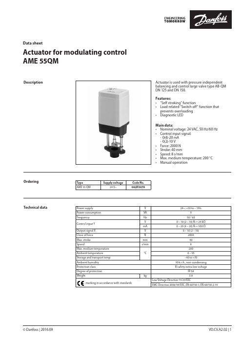
© Danfoss | 2016.09VD.CV.A2.02 | 1Actuator for modulating control AME 55QMData sheetActuator is used with pressure independent balancing and control large valve type AB-QM DN 125 and DN 150.Features:• “Self stroking” function• Load related “Switch off“ function that prevents overloading • Diagnostic LEDMain data:• Nominal voltage: 24 VAC, 50 Hz/60 Hz • Control input signal: - 0(4)-20 mA - 0(2)-10 V • Force: 2000 N • Stroke: 40 mm • Speed: 8 s/mm• Max. medium temperature: 200 °C • Manual operationDescriptionOrderingType Supply voltageCode No.AME 55 QM24 V~082H3078Technical dataPower supply V 24~; +10 to – 15%Power consumption VA 9Frequency Hz 50 / 60Control input Y V 0 – 10 (2 – 10) Ri = 24 kΩmA 0 – 20 (4 – 20) Ri = 500 ΩOutput signal X V 0 – 10 (2 – 10)Close of force N 2000Max. stroke mm 40Speeds/mm 8Max. medium temperature °C200Ambient temperature 0 – 55Storage and transport temp. –40 to +70Ambient humidity 95% r.h., non-condensing Protection class III safety extra-low voltageDegree of protection IP 54Weight kg 3.8- marking in accordance with standardsLow Voltage Directive 73/23/EECEMC-Directive 2006/95/EEC, EN 60730-1, EN 60730-2-14Data sheet Actuator for modulating control AME 55 QM2 | © Danfoss | 2016.09VD.CV.A2.02Installation MechanicalThe actuator should be mounted with the valvestem in either horizontal position or pointingupwards. Use a 4 mm Allen key (not supplied) tofit the actuator to the valve body.Allow for necessary clearance for maintenancepurposes.The valve has position indication ringswhich should be pushed together beforecommissioning; after stroking they indicate theends of the stroke.ElectricalElectrical connections can be accessed byremoving the cover. Two M16 × 1.5 cable entriesare provided. Both entries are provided with arubber grommet for use with flexible cable. Notethat in order to maintain the enclosure IP rating,appropriate cable glands must be used.Wiring The actuator must be dismantled and the elements sorted into various material groups before disposal.Disposal 24 Vac only.Wiring length Recommendedsquare of the wiring0-50 m0.75 mm2> 50 m 1.5 mm2Automatic self stroking featureWhen power is first applied, the actuator willautomatically adjust to the length of the valvestroke. Subsequently, the self stroking featurecan be re-initialised by changing position of SW9.Diagnostic LEDThe red diagnostic LED is located on the pcbunder the cover. It provides indication of threeoperational states:• Actuator Healthy (Permanently ON),• Self Stroking (Flashes once per second),• Error (Flashes 3 times per second - seektechnical assistance).Data sheetActuator for modulating control AME 55 QM© Danfoss | 2016.09 | 3VD.CV.A2.02DIP switch settingThe actuator has a function selection DIP switch under the removable cover. In particular, if SW6 is set to ON, the actuator will perform as 3-point actuator.The switch provides the following functions:• SW1: U/I - Input signal type selector:If set to OFF position, voltage input is selected. If set to ON position, current input is selected.• SW2: 0/2 - Input signal range selector:If set to OFF position, the input signal is in the range from 2 V to 10 V (voltage input)or from 4 mA to 20 mA (current input). If set to ON position, the input signal is in the range from 0 V to 10 V (voltage input) or from 0 mA to 20 mA (current input).• SW3: D/I - Direct or inverse acting selector:If set to OFF position, the actuator is direct acting (stem contracts as voltage increases). If actuator is set to ON position the actuator is inverse acting (stem extracts as voltage increases).• SW4: —/Seq - Normal or sequential modeselector:If set to OFF position, the actuator is working in range 0(2)..10V or 0(4)..20mA. If set to ON position, the actuator is working in sequential range; 0(2)..5 (6)V or (0(4)..10 (12)mA) or (5(6)..10V) or (10(12)..20mA).• SW5: 0..5V/5...10V - Input signal range insequential mode:If set to OFF position, the actuator is working in sequential range 0(2)..5 (6)V or 0(4)..10 (12)mA. If set to ON position, the actuator is working in sequential range; 5(6)..10V or 10(12)..20mA.• SW6: Prop./3-pnt - Modulating or 3-point modeselector:If set to OFF position, the actuator is working normally according to control signal. If set to ON position, the actuator is working as 3-point actuator.For this operation please refer to page 2(wiring 3-point control).When DIP switch SW6 is set to ON than allfunctions from other DIP switch become inactive.• SW7: LOG/LIN - Equal percentage or linear flowthrough valve selector:If set to OFF position, the flow through valve is equal percentage. If set to ON position, the flow through valve is linear according to control signal.• SW8: 100% K VS/Reduced K VS :To be set to OFF position (no sense in combination with AB-QM).• SW9: Reset:Changing this switch position will cause the actuator to go through a self stroking cycle.Complete the mechanical and electricalinstallation and perform the necessary checks and tests:• Isolate control medium. (e.g. self stroking in a steam application without suitable mechanical isolation could cause a hazard).• Apply the power. Note that the actuator will now perform the self stroking function.• Apply the appropriate control signal and check the valve stem direction is correct for the application.• Ensure that the actuator drives the valve over its full stroke, by applying the appropriate control signal. This action will set the valve stroke length.The unit is now fully commissioned.CommissioningCommissioning / testing featureThe actuator can be driven to the fully open or closed positions (depending on valve type) by connecting SN to terminals 1 or 3.VD.CV.A2.024 | © Danfoss | DHS-SRMT/SI | 2016.09Data sheetActuator for modulating control AME 55 QMActuator - valve combinationsThe manual override is applied by rotating the 4 mm Allen key (not supplied) to the required position. Observe the direction of the rotation symbol.• Disconnect power supply• Adjust valve position using an Allen key • Set valve to closed position •Restore power supplyIf manual override has been used then X and Y signal are not correct until the actuator reaches its end position. If this is not accepted reset the actuator, or apply accessory active return signal kit.DimensionsManual override。
丹佛斯(Danfoss) FC101和FC102变频器Novenco控制用户指南说明书

Pure competence in air.927665-0FREQUENCY CONVERTERS DANFOSS FC 101 AND FC 102NOVENCO CONTROL USER GUIDE927665-0GBFrequency converters Danfoss FC 101 and FC 102Novenco control user guideContents1.General2.Wire configuration3.First time run after installation4.Configuration of FC101 converter5.Configuration of FC102 converter6.Modbus configuration7.Reference documentation8.Patents and trademarks9.Declaration of conformity1.GeneralThe procedures in this guide serve as examples of how to control the Danfoss FC 101 and FC 102 frequency con-verters in combination with Novenco fans.Please read all relevant parts of this complete guide.Procedures and methods in this guide should be fol-lowed for the warranty to remain valid.2.Wire configurationCheck wires are correctly connected•Check that a wire connects the terminals no. 12 and 27 in the frequency converter.•Connect a control wire to terminal no. 18 in the fre-quency converter. The terminal must pull high (24V) to activate the converter.•Check the signal wire is connected to terminal no. 53. For voltage control the signal levels are 0 - 10V and for current control the levels are 4 - 20mA.•Check that ground is connected to terminals no. 20 and 55.Table 1.Icons in guideFigure 2Terminal block set up for current control3.First time run after installationHow to check the installation is correct1.Check the installation is powered off on the mainswitch.2.Check the fan and frequency converter are in-stalled correctly. Refer to the installation and maintenance guides for the fan and frequency converter.3.Power on the installation at the main switch. Thefrequency converter starts in idle mode.4.Push Hand On on the local control panel (LCP)on the frequency converter. This activates the fan rotor.5.Check the direction of rotation is consistent withthe arrows on the fan casing.6.Turn off the installation at the main switch.7.Connect the start signal wire to terminal no. 18.8.Voltage or current mode:Connect the reference wire to terminal no. 53.Modbus mode:Connect the reference wires to terminals no. 68 and 69.4.Configuration of FC101 converterThe converter is set up for voltage mode as standard. The minimum speed is indicated with 0V and the max-imum speed with 10V.Figure 3Wire diagram for the FC101+10 V DC4.1Change from voltage to current con-trolHow to change the FC101 to current control1.Push the Menu button on the LCP on the fre-quency converter.2.Push the ↓ and ↑ buttons to navigate to the Wiz-ard. Push OK to select.3.Push ↓ to navigate to the following menu item.6-19 Terminal 53 mode[1] Voltage mode4.Push OK to access and use the ↓ and ↑ to selectcurrent mode.5.Push OK to accept.The frequency converter now operates in current mode for control signals. The minimum speed is indicated with 4mA and the maximum speed with 20mA.5.Configuration of FC102 converter The converter is set up for voltage mode as standard.The minimum speed is indicated with 0V and the max-imum speed with 10V.Figure 4Wire diagram for the FC1025.1Change from voltage to current con-trolHow to change the FC102 to current control1.Remove the screw that holds the lid on the fre-quency converter.2.Pull out the LCP with a straight pull.3.Locate the text A53 U - I.4.Push the button from position U to I with ascrewdriver.5.Put the LCP back.6.Attach the lid and insert the screw.The frequency converter now operates in current mode for control signals. The minimum speed is indicated with 4mA and the maximum speed with 20mA. 6.Modbus configurationAll parameters are accessible through Modbus RTU (Re-mote Terminal Unit) either directly or via PCD (Process Data).To setup the Modbus RTU1.Push the Menu button two times.2.Push ↓ to navigate to8-** Comm. and Options.3.Push OK.4.Push ↓ to navigate to 8-3 FC port settings.5.Push OK.6.Push OK again.7.Push ↓ to navigate to [2] Modbus RTU.8.Push OK to confirm.9.Push ↓ to navigate down and check the followingsettings.•Address•Baud Rate•Parity / Stop bit•Minimum Response Delay•Maximum Inter-char..10.Push OK to select, the ↓ and ↑ buttons to changeand push OK to confirm settings.Write and start-stop notes•PCD: It is possible to configure up to 64 parame-ters in PCDs.Write PCDs in par. 8-42.xx, and read PCDs in par.8-43.xx. These PCDs are accessible via holdingregisters 28xx and 29xx.•Write control word: Par. 8-42.0 and par. 8-42.1 areset to the control word and as reference, respec-tively. Set par. 8-42[2-63] to the par. no. to write to.•Start-stop: Write the control word to register 2810to start or stop the converter.Read notes•The reference register is 2811 with 0 - 4000hex(0-100%).•Read status word: Par. 8-43.0 and par. 8-43.1 areset to status word and main actual value, respec-tively. Set par. 8-43[2-63] to the par. no. to readfrom.Figure 5Location of terminal 53Bit Bit value = 0Bit value = 100Reference value External selection LSB01Reference value External selection MSB02DC brake Ramp03Coasting No coasting04Quick stop Ramp05Hold output frequency Use ramp06Ramp stop Start07No function Rest08No function Jog09Ramp 1Ramp 210Data invalid Data valid11Relay 01 open Relay 01 active12Relay 02 open Relay 02 active13Parameter set-up Selection LSB14< Not used >< Not used >15No function ReverseTable 2.Control word bit positions•Read status word: Read the status word from reg-ister 2910.Other notes•Set the speed, i.e. the main actual value, with reg-ister 2911.•Read the configuration of par. 8-43.3.. with regis-ter 2912.•To configure a PCD to read a 32bit parameter re-quires configuration of two consecutive PCDs to the same parameter. For example, the parameter 16-10 Power [kW] is a 32bit integer, which may be configured in par. 8-43.2 and 8-43-3, or par. 8-43.4 and 8-43.5 and so on.The sizes of the different parameters are available in the programming guide.•To address parameters directly use the register no. = parameter no. x 10. For example, the par. 16-90 is accessible via register no 16900.•Some PLCs have 0 offsets, which means the value 1 must be subtracted from the register no. For ex-ample, reg. 2810 is 2809 etc.00Control not ready Control ready 01Drive not ready Drive ready 02Coasting Enable 03No error Trip04No error Error (no trip)05Reserved -06No error Triplock 07No warningWarning08Speed reference Speed = reference 09Local operationBus control10Out of frequency limit Frequency limit ok 11No operation On operation12Drive ok Stopped, auto start 13Voltage ok Voltage exceeded 14Torque ok Torque exceeded 15Timer okTimer exceededTable 3.Status word bit positionsNovenco Building & Industry A/S Industrivej 22Tel. +45 70 77 88 994700 Naestved Denmark7.Reference documentation•Danfoss Operating guideVLT ® HVAC basic drive FC 101Publication no. MG18AA02, 04/2018•Danfoss Programming guide VLT ® HVAC basic drive FC 101Publication no. MG18B502, 04/2018•Danfoss Design guideVLT ® HVAC basic drive FC 101Publication no. MG18C802, 04/2018•Danfoss Operating guide VLT ® HVAC drive FC 102Publication no. MG16O202, 04/2018•Danfoss Programming guide VLT ® HVAC drive FC 102Publication no. MG11CE02, 03/2015•Danfoss Design guide VLT ® HVAC drive FC 102Publication no. MG11BC02, 06/20148.Patents and trademarksNovenco ®ZerAx ® is a registered trademark of Novenco Building & Industry A/S.AirBox™ and NovAx™ are trademarks of Novenco Building & Industry A/S.VLT ® is a registered trademark of Danfoss A/S.The ZerAx ® processes of manufacture, technologies and designs are patented by Novenco A/S or Novenco Building & Industry A/S.Pending patents include Brazil no. BR-11-2012-008607-3, BR-11-2012-008543-3, BR-11-2012-008545-0, BR-11-2014-002282-8 and BR-11-2014-002426-0; India no. 4140/CHENP/2012, 4077/CHENP/2012, 821/CHENP/2014 and 825/CHENP/2014; PCT no. EP2012/064908 and EP2012/064928; South Korea no. 10-2012-7012154.Granted patents include Canada no. 2.777.140,2.777.141, 2.777.144, 2.832.131 and 2.843.132; China no. ZL2010800458842, ZL2010800460965, ZL2010800464275 and ZL2012800387210; EU no. 2488759, 2488760,2488761, 2739860 and 2739861; India no. 312464; South Korea no. 10-1907239, 10-1933724, 10-1980600 and 10-2011515; US no. 8.967.983, 9.200.641, 9.273.696 B2,9.683.577 and 9.926.943 B2. Granted designs include Bra-zil no. BR-30-2012-003932-0; Canada no. 146333; China no. 1514732, 1517779, 1515003, 1555664 and 2312963; EU no. 001622945-0001 to 001622945-0009 and 001985391 - 0001; India no. 246293; South Korea no. 30-0735804; US no. D665895S, D683840S, D692119S, D704323S,D712023S, D743018S, D755363S, D756500S, D821560S and D823452S.The NovAx Basic jet fans manufacturing processes, technologies and designs are patented by Novenco A/S or Novenco Building & Industry A/S.Granted patents include EU no. 2387670 and United Arab Emirates no. 1372. Granted designs include EU no. 001069884-0003, 001069884-0008, 001069884-0010, 001069884-0013, 001069884-0017, 001069884-0019, 001069884-0022, 001069884-0026 and 001069884-0028; United Arab Emirates no. D223/2009.The CGF jet fans designs are patented by Novenco A/S or Novenco Building & Industry A/S.Granted designs include EU no. 001610643-0001 to 001610643-0005.Copyright © 2016 - 2020,Novenco Building & Industry A/S.All rights are reserved.9.Declaration of conformityRefer to the declaration information in the documenta-tion for the fans and frequency converters.Figure 6QR code to this guide onPure competence in air. ttt͘EKs E Kͳ h/> /E'͘ KD。
丹福斯(Danfoss)VQ系列单栓单轴泵技术服务和零件手册说明书
I-3165-SRevised 07–01–97Vane Type Single Pump25/26/30/31 VQ Series - 20 DesignService and Parts ManualVickers by Danfoss®Vane PumpsAX438768117869en-000101WARNING: USE THIS FOR PARTS INFORMATION ONLY.SEE OVERHAUL MANUAL I-3144-S FOR MAINTENANCE INFORMATION.Model CodeViton SealsSeriesVane TypeSAE Rated CapacityPort ConnectionsMounting & Shaft SealsAssemblyShaftsPort PositionsDesignRotation(Omit if not required.)25, 26, 30, 31(Rating @ 1200 RPM - 100 psi)See Capacity (USgpm)See Table InsideCode Inlet OutletConnection ConnectionA SAE 4-Bolt SAE 4-BoltB SAE Str. Thd.SAE Str. Thd.C SAE 4-Bolt SAE Str. Thd.D SAE Str. Thd.SAE 4-BoltF - Foot (Single Shaft Seal Assy.)S - Flange (Double Shaft Seal Assy.)Omitted-Flange (Single Shaft SealAssy.)See Table InsideSee Chart BelowL - Left Hand (CCW Rotation)Omitted - Right Hand RotationFor satisfactory service life of these components, use full ow ltration to provide uid which meets ISO cleanliness code 18/16/13 or cleaner. Selections from pressure, return, and in-line lter series are recommended.Danfoss Power Solutions is a global manufacturer and supplier of high-quality hydraulic and electric components. We specialize in providing state-of-the-art technology and solutions that excel in the harsh operating conditions of the mobile off-highway market as well as the marine sector. Building on our extensive applications expertise, we work closely with you to ensure exceptional performance for a broad range of applications. We help you and other customers around the world speed up system development, reduce costs and bring vehicles and vessels to market faster.Danfoss Power Solutions – your strongest partner in mobile hydraulics and mobile electrification.Go to for further product information.We offer you expert worldwide support for ensuring the best possible solutions foroutstanding performance. And with an extensive network of Global Service Partners, we also provide you with comprehensive global service for all of our components.Local address:DanfossPower Solutions GmbH & Co. OHG Krokamp 35D-24539 Neumünster, Germany Phone: +49 4321 871 0DanfossPower Solutions ApS Nordborgvej 81DK-6430 Nordborg, Denmark Phone: +45 7488 2222DanfossPower Solutions (US) Company 2800 East 13th Street Ames, IA 50010, USA Phone: +1 515 239 6000DanfossPower Solutions Trading (Shanghai) Co., Ltd.Building #22, No. 1000 Jin Hai Rd Jin Qiao, Pudong New District Shanghai, China 201206Phone: +86 21 2080 6201Danfoss can accept no responsibility for possible errors in catalogues, brochures and other printed material. Danfoss reserves the right to alter its products without notice. This also applies to products already on order provided that such alterations can be made without subsequent changes being necessary in specifications already agreed.All trademarks in this material are property of the respective companies. Danfoss and the Danfoss logotype are trademarks of Danfoss A/S. All rights reserved.Products we offer:•Cartridge valves •DCV directional control valves•Electric converters •Electric machines •Electric motors •Gear motors •Gear pumps •Hydraulic integrated circuits (HICs)•Hydrostatic motors •Hydrostatic pumps •Orbital motors •PLUS+1® controllers •PLUS+1® displays •PLUS+1® joysticks and pedals•PLUS+1® operator interfaces•PLUS+1® sensors •PLUS+1® software •PLUS+1® software services,support and training •Position controls and sensors•PVG proportional valves •Steering components and systems •TelematicsHydro-GearDaikin-Sauer-Danfoss。
丹佛斯制冷空调系统配件使用手册、售后维修注意事项及方法

故障排除
© Danfoss A/S (RA Marketing/MWA), , 04-2007
DKRCC.PF.000.G1.41 / 520H1981
147
注释
装配说明
故障排除 — 测量仪器
148
DKRCC.PF.000.G1.41 / 520H1981
© Danfoss A/S (RA Marketing/MWA), , 04-2007
Ae0_0004
电子仪器
电子仪器对湿度很敏感。 。 如果电子仪器从冰冷的环境中移入温暖的环境 中后立刻开始工作,则冷凝物可能会损坏一些 电子仪器。 。 这些电子仪器必须在经过一段时间后整个仪器 的温度达到环境温度时才能开始工作。 。 当电子设备从冰冷的维修车中移入温暖的环境 中后,请勿马上使用该电子设备。
装配说明
故障排除 — 测量仪器
测量仪器
查找故障的仪器
以下是在制冷系统中确定故障位置时最为常用 的设备: 1. 压力计 2. 温度计 3. 湿度计 4. 检漏器 5. 真空计 6. 钳式安培计 7. 高阻表 8. 极性测定器
90
Ae0_0045
仪器分类
用于制冷系统故障查找和维护的仪器应该满足 某些可靠性要求。 。 对于这其中的一些要求,我们可以做出如下 分类: a. 不确定性 b. 辨析率 c. 可重复性 d. 长期稳定性 e. 温度稳定性其中 最重要的是 a、b 和 e 项。
© Danfoss A/S (RA Marketing/MWA), , 04-2007
装配说明调节(续)
可以由授信的测试机构对仪器进行适当的最终 检查和调节。 。
故障排除
© Danfoss A/S (RA Marketing/MWA), , 04-2007
丹佛斯焊接球阀技术资料
JIP球阀(PN16,25,40)
描述
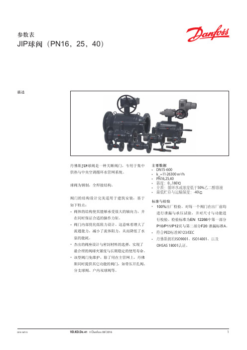
丹佛斯JIP球阀是一种关断阀门,专用于集中 供热与中央空调循环水管网系统。
球阀为钢制,全焊接结构。
阀门的结构设计完美适用于建筑安装,基于 如下特点: • 阀体的结构使其能够承受很大的轴向力,并
在同时保证合适的操作力矩。 • 阀门内部优化低阻力设计。这意味着增大了
065N0282
产品编号 FF PN 25
阀门带有 蜗轮机构
阀门带有 蜗轮法兰
065N0331
065N0332
065N0336
065N0337
065N0341
065N0342
065N0346
065N0347
065N0351
065N0352
065N0356
065N0357
065N0361
065N0362
低阀杆T型手柄
065N0900 065N0905 065N0910 065N0915 065N0920 065N0925
065N0904 065N0908 065N0914
4
VD.KD.D6 .41 © Danfoss 08/2016
DEN-SMT/SI
参数表
球阀
订货
室内安装 双阀,单管 T型手柄(DN15-25) 或L型手柄(DN32-50) JIP-WW 焊接 JIP-II内螺纹 JIP-IW内螺纹/焊接
流通能力,减小了流体阻力,从而降低了水 泵的能耗。 • 杰出的阀座设计与密封材料的选择,实现了 最合理的阀球夹紧度与长期稳定的使用寿命。 • 该型阀门免维护,除了用在主管网上,丹佛 斯同时提供其它功能的阀门,如带压开孔阀、 分支球阀、户内双球阀等。
主要数据 • DN15-600 • kvs=11-26300 m3/h • PN16,25,40 • 温度:0...180°C • 介质:循环水或浓度低于50%乙二醇溶液 • 最低贮存与运输温度:-40°C
丹佛斯Danfoss动态压差平衡阀ASV参数表-水力平衡
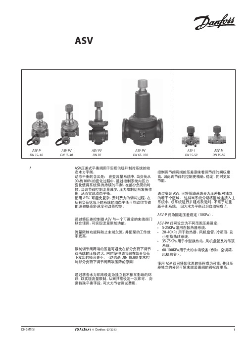
图 4 ASV用于地板采暖系统中分集水器前
ASV 阀用于地板采暖系统。为实现对每个环路的 流量限制,应将带有预设定的分集水器与 ASV-PV 阀提供的恒定压差控制配合使用。或者通过使用
具有设定功能 ASV-I 实现对整个分集水器的流量 限制。
如需不同的设定压差,ASV-PV 的设定压差具有数 个的可选范围。由于尺寸紧凑,ASV 动态压差平衡 阀易于安装于挂墙的分集水器安装盒内。
型号
备注
螺纹尾管(1 件)
焊接尾管(1 件)
连接至管道 R½ R¾ R1 R 1¼ R 1½
R2
DN 15 DN 20 DN 25 DN 32 DN 40
DN 50
注意: ASV-PV DN 50 (2½”) 和 ASV-I/M DN 50 (2¼”) 的接头口径不同。 1) 与 ASV-PV DN 50 阀配套使用 2) 与 ASV-I 和 ASV-M DN 50 配套使用。
ASV-P 阀为固定压差设定(10KPa)。
ASV-PV 阀可设定为不同范围压差设定: • 5-25KPa 常用在散热器系统, • 20-40KPa 用于散热器、风机盘管、冷吊顶、及
小型换热站系统, • 35-75KPa 用于小型换热站、风机盘管及冷吊顶
系统, • 60-100KPa 用于大的末端设备(例如:空调箱、
22
VD.A1.T8.41 © Danfoss 07/2013
DH-SMT/SI
DH-SMT/SI
VD.A1.T8.41 © Danfoss 07/2013
3
参数表 描述 / 应用 (续)
动态压差平衡阀 ASV
参数表
保温材料
图 +5 ASV 用于风机盘管系统
danfoss LENO MSV-B静态平衡阀 说明书

kv-信号值适用于非丹佛斯的测量仪。 丹佛斯 PFM 3000*/4000 测量仪在内存中有全部数据,
并且使用下面的计算公式:
∆p(kv-sig)和阀门的 ∆p(kv-val)并不一致。 * 使用 9.4 或更高版本的软件。
设定值
0.0 0.1 0.2 0.3 0.4 0.5 0.6 0.7 0.8 0.9 1.0 1.1 1.2 1.3 1.4 1.5 1.6 1.7 1.8 1.9 2.0 2.1 2.2 2.3 2.4 2.5 2.6 2.7 2.8 2.9 3.0 3.1 3.2 3.3 3.4 3.5 3.6 3.7 3.8 3.9 4.0 4.1 4.2 4.3 4.4 4.5 4.6 4.7 4.8 4.9 5.0 5.1 5.2 5.3 5.4 5.5 5.6 5.7 5.8 5.9 6.0 6.1 6.2 6.3 6.4 6.5 6.6
应用
独栋住宅的锅炉、小型换热站或热泵。
• 提供平衡。 • 用于检修/修理的关断功能。
空气处理设备
• 提供定流量。 • 提供平衡。 • 用于检修/修理的关断功能。
HEC-HB
VDB4I141 © Danfoss 09/2009
1
参数表 应用
静态平衡阀 LENO™ MSV-B
订货
风机盘管
• 用于流量检定。 • 用于检修/修理的关断功能。
kvs(m3/h) 2.5 3.0 6.0 9.5 18 26 40
连接
Rp ½" Rp ½" Rp ¾" Rp 1" Rp 1¼" Rp 1½" Rp 2"
产品编号
003Z4030 003Z4031 003Z4032 003Z4033 003Z4034 003Z4035 003Z4036
丹佛斯变频器说明书【范本模板】

丹佛斯变频器按键功能:(DISPLAY/STATUS)键用于选择显示模式或者从快速菜单模式、菜单模式变回显示模式。
(QUICK MENU)键用于在快速菜单模式下进行参数编程.可以从快速菜单和菜单模式之间直接转换. (MENU)键用于对所有参数进行编程。
可以从菜单模式和快速菜单模式之间直接转换. (CHANGE DATA)键用于在菜单模式或快速菜单模式下改变所选参数。
(CANCEL)键用于取消所选参数.(OK)键用于确定和储存所选参数。
(+/-)键用于选择或改变所选参数。
这些键也可在显示模式下使用。
(〈〉)键用于选择参数组和在改变数字参数时移动光标。
(STOP/RESET)键用于停止电机运作或用于VLT变频器跳闸后重新复位。
(JOG)键被按下时,它会将输出频率改变为预设的频率。
(FWD/REV)键改变在操作器显示屏上用箭头指示的电机旋转方向,(START)键用于启动通过(STOP/RESET)键停动的VLT变频器.该键始终处于有效状态,但不能超越由端子发出的停止命令.操作步骤:1、按(MENU)键进入功能菜单。
2、按(+/-)或(<>)键选择参数。
3、按(CHANGE DATA)键进入数据改变模式。
4、按(+/-)键改变数据值。
5、按(OK)键存储改变的数据.6、按(DISPLAY/STATUS)键返回到正常模式。
变频器故障内容(10VOLTLOW)警告1:低于10V(LIVE ZERO ERROR)警告/报警2:电流信号零点故障(NO MOTOR)警告/报警3:无电机(MAINS PHASE LOSS)警告/报警4:缺相(DC LINK VOLTAGE HIGH)警告5:高电压警告(DC LINK VOLTAGELOW)警告6:低电压警告(DC LINK OVERVOLT)警告7:过电压(DC LINK UNDERVOLT)警告/报警8:欠电压(INVERTER TIME)警告/报警9:逆变器过载(MOTOR TIME)警告/报警10:电机温度过高(MOTOR THERMISTOR)警告/报警11:电机过热(热敏电阻)(TORQUE LIMIT)警告/报警12:过转矩极限(OVERCURRENT)警告/报警13:过电流(EARTH FAULT)报警14:接地电流(SWITCH MODE FAULT)报警15:载波模式故障(CURR。
- 1、下载文档前请自行甄别文档内容的完整性,平台不提供额外的编辑、内容补充、找答案等附加服务。
- 2、"仅部分预览"的文档,不可在线预览部分如存在完整性等问题,可反馈申请退款(可完整预览的文档不适用该条件!)。
- 3、如文档侵犯您的权益,请联系客服反馈,我们会尽快为您处理(人工客服工作时间:9:00-18:30)。
压力设备指令(PED) REG 过滤器符合压力设备指令中规定的欧洲标 准,并带有欧盟强制认证标识。
REG-SA 和 REG-SB 阀门 公称管径 分类目的 类别 第3条第3段 DN = < 25 毫米(1 英寸) DN32-80 毫米 (1¼ - 3 英寸) 液体组 I II III DN100 – 125 毫米(4 - 5 英寸)
R717
A B
0%
25%
50%
䕈ⱘ䕀ࡼ
100% ᠧᓔ
图6
गܟᇣᯊ
(⺙ߚ䩳) 8000 (294)
REG-SA 15-20 和 REG-SB 15-20
∆P = 2 bar (29 psi) ∆P = 1.5 bar (22 psi) ∆P = 1 bar (14 psi) ∆P = 0.5 bar (7 psi)
图2
4
REG-SA 15-20 和 REG-SB 15-20
B
A
2
3 25%
4
5 50%
6
7 75%
8
9 100%
䕈ⱘ䕀ࡼ ᠧᓔ
DKRCI.PD.KM1.A6.41 / 520H7320
© Danfoss A/S (MWA), 2015-01
REG-SA 型和 REG-SB 型手动调节阀 计算和选择(续) 流量系数
© Danfoss A/S (MWA), 2015-01
DKRCI.PD.KM1.A6.41 / 520H7320 3
REG-SA 型和 REG-SB 型手动调节阀 计算和选择 流量系数
Kv (Cv) 0.6 (0.70) 0.5 (0.58) 0.4 (0.46) 0.3 (0.35) 0.2 (0.23) 0.1 (0.12) 0
REG-SB 50
B
2
3
4 25%
5
6
7 50%
8
9
10 75%
11
12
13
䕈ⱘ䕀ࡼ
100% ᠧᓔ
DKRCI.PD.KM1.A6.41 / 520H7320 5
REG-SA 型和 REG-SB 型手动调节阀 计算和选择(续) 流量系数
Kv (Cv) 80 (92.8) 70 (81.2) 60 (69.6) 50 (58.0) 40 (46.4) 30 (34.8) 20 (23.2) 10 (11.6) 0 0 1 0%
Cv [US 加仑/分钟] 在1 psi 的压力损失下流 经阀门的水量[US 加仑/ 分钟]。 P1 [psi] 阀门前压力(上游)。 P2 [psi] 阀门后压力(下游)。 ∆p [psi] 通过阀门的实际压力损 失(P1-P2)。 G [磅/分钟] 通过阀门的质量流量。 [US 加仑/分钟] 通过阀门的体积流量。 ρ [磅/立方英尺] 阀门前的制冷剂密度 CA 换算因子(图11)。
MAKING MODERN LIVING POSSIBLE
技术手册
手动调节阀 REG-SA 和 REG-SB
REG-SA 和 REG-SB 是一种角通型和直通型手动 调节阀,该阀门在关闭位置时可作为普通关 断阀。 阀门有两种不同版本 - REG-SA 与 REG-SB, 设计用途为液体膨胀线路内的调节设备。 该阀门符合国际分类协会规定的针对制冷安 装的严格质量要求,提供良好的流动条件和 精确的直线特性。 REG-SA 和 REG-SB 配备通风盖和内部后座,可 以在阀门处于运行中,例如处于压力下时对 轴封进行更换。
干吸管线 湿吸管线
排出管线
REG 没有相变的液体管线 有来自变或没有相变的液体管线选择适用于液体的手动调节阀 液体制冷剂:使用液体表,图 6 – 10。用于其他 制冷剂和盐水,“正常流量”(湍流);请参见下 文并使用流量系数表(图1-5)。 SI-单位 质量流量: 英制单位 质量流量:
体积流量:
体积流量:
kv [立方米/小时] 在1 bar的压力损失下通 过阀门的水流量[立方 米/小时](根据VDE/VDI Norm 2173)。 P1 [bar] 阀门前压力(上游)。 P2 [bar] 阀门后压力(下游)。 ∆p [bar] 通过阀门的实际压力损失 (P1-P2)。 G [千克/小时] 通过阀门的质量流量。 [立方米/小时] 通过阀门的体积流量。 ρ [千克/立方米] 阀门前的制冷剂密度。 CA 换算因子(图11)。
Kv (Cv) 20 (23.20) 18 (20.88) 16 (18.56) 14 (16.24) 12 (13.92) 10 (11.60) 8 (9.28) 6 (6.96) 4 (4.64) 2 (2.32) 0 0 1 0% 2 3 4 25% 5 6 50% 7 8 9 75% 10 11 12 100% 䕈ⱘ䕀ࡼ ᠧᓔ
0 1 2 3 4 5 6 7 8 9 10 11 12 13
最大运行压力:52 bar(754 psig) 温度范围:–60/+150°C (–76/+302°F) 在封闭位置用作正常截止阀。 阀套和阀帽材料为符合压力设备指令和其他 国际分类当局要求的低温钢。 使用 Coolselector®2(丹佛斯计算和选型软 件)可以准确计算该阀门在采用各种制冷剂 时的制冷量和设定。 分类:如需获取产品证明的更新列表,请与 当地的 Danfoss 销售企业联系。
REG-SA 型和 REG-SB 型手动调节阀 计算和选择(续) 液体 R 717,密度:670 千克/立方米 [42 磅/立方英尺]
गܟᇣᯊ
(⺙ߚ䩳) 30000 (1103) 20000 (735) 10000 (368)
0 1 2 3 4 5 6 7 8 9 10 11 12
REG-SA 25-40 和 REG-SB 25-40
© Danfoss A/S (MWA), 2015-01
DKRCI.PD.KM1.A6.41 / 520H7320 1
REG-SA 型和 REG-SB 型手动调节阀 设计 阀套 阀套为标准 SVA 角式或直通式阀套,可以安装 来自 SVA 平台的其他插入物。 材料为特殊抗寒钢 连接 提供以下连接: 对接焊 DIN(EN 10220) – DN 10 – 65(3/8 - 2½英寸) 对接焊 ANSI(B 36.10 附表 80) – DN 10 - 40(3/8 - 1½ 英寸) 对接焊 ANSI(B 36.10 附表 40) – DN 50 - 65(2 - 2½ 英寸) 承插焊(ANSI B 16.11) – DN 15 - 40(½ - 1½ 英寸) FPT 管内螺纹,NPT(ANSI/ASME B 1.20.1) – DN 15 - 32(½ - 1¼ 英寸) 轴 轴由抛光不锈钢制成,非常适合于O型环密封。 填料 - REG-SA 和 REG-SB “全温度范围”填料可以在整个温度范围内确保 完美的密闭性。–60/+150°C(–76/+302°F)填料 配备刮油环,可以防止尘土和冰渗入。 安装 安装阀门时应使轴处于垂直或水平位置。流体必 须被导向阀锥。 该阀门可以承受很高的内部压力。但是,管道系 统的总体设计应避免液阱并减少热膨胀所造成的 液压风险。 详情请参见 REG-SA 和 REG-SB 的产品说明。
2
DKRCI.PD.KM1.A6.41 / 520H7320
© Danfoss A/S (MWA), 2015-01
REG-SA 型和 REG-SB 型手动调节阀 计算和选择 介绍 在制冷设备中,手动调节阀主要在液体管路中使 用,以调节制冷剂流量。此外,该阀门还能作为 膨胀阀使用。从计算的角度看,这两种用于领域 截然不同。 正常流量用指的是经过阀门的流量与阀门压降的 平方根成正比,与制冷剂密度成反比(伯努利方 程)。
阀锥 这些阀门分为两种,带A阀锥的 REG-SA 和带 B阀 锥的 REG-SB。A 阀锥用于扩展管线,B 阀锥用于 调节目的,例如液体管线。 该阀锥可以确保完美的调节,并提供宽阔的调节 区域。不论使用何种制冷剂,都便于获得正确的 容量。阀锥密封环可以最小闭合力提供完美的密 封。 该阀锥可以在轴上转动,因此当阀门打开或关闭 时阀锥和阀座之间没有摩擦。 标注环示例,REG-SA
गܟᇣᯊ ⺙ߚ䩳 800 (29.4)
REG-SA 10 和 REG-SB 10
∆P = 2 bar (29 psi) ∆P = 1.5 bar (22 psi) ∆P = 1 bar (14 psi)
400 (14.7)
∆P = 0.5 bar (7 psi)
0 1 2 3 4 5 6 7 8 75%
∆P = 2 bar (29 psi) ∆P = 1.5 bar (22 psi) ∆P = 1 bar (14 psi) ∆P = 0.5 bar (7 psi)
R717
A B
0%
25%
50%
75%
䕈ⱘ䕀ࡼ
100% ᠧᓔ
图8
गܟᇣᯊ
(⺙ߚ䩳) 60000 (2206) 45000 (1654) 30000 (1103) 15000 (551)
系统中的阀门位置(标注绿色) 热气旁通和除霜管线。
质量流量、压降和密度之间的关系满足大部分阀 门对制冷剂和盐水的应用。 正常流量的特点是通过阀门的湍流没有相变。 下列容量曲线基于上述假设。 在正常流动范围之外采用手动调节阀的应用将显 著降低阀门的制冷量。这类情况下,建议使用 Coolselector®2(丹佛斯计算和选型软件)。
特性
适用于 HCFC, HFC, R717(氨)和 R744 (二氧化碳)。 可以用于化学和石油化工方面。 模块概念: - 每个阀套均可用于若干不同的连接类型和 尺寸。 - 只需替换完整顶部零件,REG-SA 或 REGSB 即可转换为 Flexline™ SVL 系列的其他任 意产品(关断阀、截止止回阀、止回阀或 过滤器)。 迅速便捷的阀门检修服务。便于更换顶部部 件且无需焊接。 可以确保完美的调节。 内部后座可以确保在阀门的活跃状态下,例 如在压力下对轴封进行更换。 易于拆卸以便进行检查和可能的维修。 用户可从部件单中订购用于隔热系统的加长 版(DN 15 至 DN 40)。