TYPE 550电气转换器说明书(有接线端子)
中文智能转换器说明书

MGG/C型电磁流量计使用说明书开封威利仪表有限公司MGG/C型电磁流量计使用说明书1 产品用途与适用范围1.1 特点:■可编程频率低频矩形波励磁,提高了流量测量的稳定性,功率损耗低;■采用16位嵌入式微处理器,运算速度快。
精度高;■全数字量处理,抗干扰能力强,测量可靠,精度高,流量测量范围度可达1500 : 1;■超低EMI开关电源,适用电源电压变化范围大。
抗EMC性能好;■全汉字菜单操作,使用方便,操作简单,易学易懂;■高清晰度背光LCD显示;■具有双向流量测量、双向总量累计功能,电流、频率具备双向输出功能。
■内部具有三个积算器可分别显示正向累计量、反向累计量及差值积算量。
■具有RS485或RS232C数字通讯信号输出;■具有电导率测量功能,可以判别传感器是否空管;■恒流励磁电流范围大,可与不同公司、不同类型的电磁流量传感器配套使用;■具有自检与自诊断功能;■采用SMD器件和表面安装(SMT)技术,电路可靠性高;■仪表内部设计有不掉电时钟,可记录16次掉电时间。
1.2主要用途MGG/C型电磁流量计用来测量封闭管道中导电流体的体积流量。
广泛地适用于石油化工、钢铁冶金、给水排水、水利灌溉、水处理、环保污水总量控制、造纸、医药、食品等工、农业部门的生产工艺过程流量测量和控制;适用于导电液体的总量计量。
1.3正常工作条件环境温度:分体型–10~+ 60℃;相对湿度:5%~90%;供电电源:单相交流电85~265V,45~63Hz;功率:与传感器配套,小于20W。
1.4 试验参比条件环境温度:20℃±2℃相对湿度:45%~85%电源电压:220±2%电源频率:50Hz±5%谐波含量小于5%。
预热时间:30min2产品型式转换器与传感器分离安装的分体型和与传感器组成一体的一体型两种结构形式。
3工作原理电磁流量计的工作原理基于法拉第电磁感应定律。
当一个导体在磁场内运动,在与磁场方向、运动方向相互垂直方向的导体两端,会有感应电动势产生。
True Blue Power 9018558 电源转换器手册说明书
Revision K• June 8, 2022FOREWORDThis manual provides information intended for use by persons who, in accordance with current regulatory requirements, are qualified to install this equipment. If further information is required, please contact:True Blue Powerc/o Mid-Continent Instrument Co., Inc.Attn: Customer Service Dept.9400 E. 34th St. N. Wichita, KS 67226 USA Phone 316-630-0101 Fax 316-630-0723We welcome your comments concerning this manual. Although every effort has been made to keep it free of errors, some may occur. When reporting a specific problem, please describe it briefly and include the manual part number, the paragraph/figure/table number and the page number. Send your comments to:True Blue Powerc/o Mid-Continent Instrument Co., Inc.Attn: Technical Publications9400 E. 34th St. N. Wichita, KS 67226 USA Phone 316-630-0101 Fax 316-630-0723© Copyright 2016Mid-Continent Instrument Co., Inc.Download the current version of thisinstallation manual using yoursmartphone or tablet.TABLE OF CONTENTSSECTION 1 GENERAL DESCRIPTION 41.1 INTRODUCTION 4 1.2 TECHNICAL SPECIFICATIONS 5SECTION 2 PRE-INSTALLATION CONSIDERATIONS 62.1 COOLING 6 2.2 EQUIPMENT LOCATION 6 2.3 ROUTING OF CABLES 6 2.4 LIMITATIONS 6 2.5 MODIFICATION 7SECTION 3 INSTALLATION 83.1 GENERAL INFORMATION 8 3.2 UNPACKING AND INSPECTING EQUIPMENT 8 3.3 CABLE HARNESS 8 3.4 MOUNTING 11 3.5 INSTALLATION CAUTION 11 3.6 INSTALLATION COMPLETION 11 SECTION 4 OPERATION 124.1 ELECTRICAL PERFORMANCE 12 4.2 TC120AVILABLE CURRENT OVER THE OUTPUT VOLTAGE RANGE 12 4.3 PROTECTIVE FEATURES 13 SECTION 5 CONFORMANCE 155.1 INSTRUCTIONS FOR CONTINUED AIRWORTHINESS 15 5.2 ENVIRONMENTAL QUALIFICATION STATEMENT 15REVISION HISTORYRev Date Detail Approved A 02/10/2016 Initial release SHOB 03/04/2016 Updated EQF in Section 5, corrected input voltage range,added note to Section 2.4.BAWC 03/15/2016 Add -2 version.BAWD 05/27/2016 Updated wiring drawings in Section 3.VAAE 02/10/2016 Updated Section 4.2.1.KJWF 05/07/2020 Updated style and brand to meet Marketing and Engineering guidelines.DLRG 10/21/2020 Updated weight.MEKH 04/13/2021 Updated Section 4 – provided additional clarification in theoperation section; correct graph info; added new graph toillustrate power range.Section 5 corrected typoDLRJ 09/03/2021 Updated Sections 1.1, 1.2 and 5.2 to include MIL-STD testing WVCK 06/08/2022 Updated adjustable output range from 5-18VDC to 5-24VDCfor MOD 1 units. Updated Figures 4.1 and 4.2 accordingly.BAWSECTION 1 GENERAL DESCRIPTION1.1 INTRODUCTIONThe model TC120 DC/DC Power Converter is a lightweight power converter that translates a direct current (DC) input of 28 volts to an adjustable 5 to 24 volt direct current (DC) output.The input operating voltage (24–32VDC) makes the TC120 suitable for nearly any common general, business, or commercial aviation application and provides an adjustable DC output voltage of 5 to 24 VDC. The unit is rated for a nominal output of 120 watts to power avionics, instrumentation, personal charging, lighting, and many other applications. The TC120 DC/DC Converter is FAA certified to TSO-C71 and tested to rigorous environmental standards and levels of RTCA DO-160G, MIL-STD-810, MIL-STD-704 and MIL-STD-461. The small size and light weight in conjunction with its installation flexibility (inside or outside the pressure vessel) make it an ideal choice for aircraft power needs while reducing the challenges associated with other similar products.Highlighted features include short circuit protection, overload capability, low input voltage shut-down, temperature monitoring, reverse polarity protection, a self-resettable over-temperature disable and an optional remote enable (on/off) feature.The TC120 DC/DC converter has a robust Military-rated circular connector and a rugged aluminum case which dissipates heat and provides excellent mechanical strength. It is engineered to require no external cooling and contains no internal fans or cooling methods, which saves energy, reduces weight and allows more flexible installation locations. At only 11 ounces (312 g), it is lighter and smaller than any other certified solution in the aviation market today.1.2 TECHNICAL SPECIFICATIONSElectrical AttributesInput Voltage Rated 28VDC nominal, Operating 24 – 32VDC Input Current (full load) 5 amps max at nominal input voltageOutput Voltage 5 – 24 VDC adjustableOutput Power 120 watts nominalEfficiency 95% nominalTable 1.1Physical AttributesWeight 11.0 oz (312g)Dimensions(not including connector mate) 2.75 long x 3.75 wide x 1.29 high [inches] 69.9 long x 95.3 wide x 32.8 high [mm]Mating Connector Kit MCIA P/N 9018651Mounting Base mount – orientation not criticalTable 1.2QualificationsCertification FAA TSO-C71Environmental Qualification RTCA DO-160G,MIL-STD-461F, MIL-STD-704F & MIL-STD-810F; See Section 5.2Altitude -15,000 feet to +55,000 feet (65,000 feet non-operating)Temperature -55°C to +70°C (-67°F to +158°F)Table 1.3SECTION 2 PRE-INSTALLATION CONSIDERATIONS2.1 COOLINGThe TC120 product does not require external cooling or contain internal active cooling. Cooling of the unit occurs exclusively through passive conduction through the base or radiated cooling across the metal case. Additional cooling can be realized through convection (exposure to free moving air) or conduction (mounting to a thermally conductive metal surface). These methods are not required to achieve rated performance but can help prevent potential overheating and extend life when the unit is operated at full power or during overload conditions. Specifically, mounting the unit to a metal surface is preferred, but not required.2.2 EQUIPMENT LOCATIONThe TC120 is designed for mounting flexibility, allowing for installation inside or outside the pressure vessel with no requirement for temperature control. In addition to altitude and temperature resistance, the unit is also designed to withstand high levels of condensing humidity. However, installation locations where the unit could be subject to standing or direct water exposure should be avoided. The unit can be mounted in any orientation. Clearance should be provided for the mating connector and may require as much as five inches past the unit connector to allow for back shell access to the connector.2.3 ROUTING OF CABLESThe wires and cable bundle associated with the unit are heavy gauge wire and carry significant power. Be aware of routing cables near other electronics or with other wire bundles that may be susceptible to high energy flow.Avoid sharp bends in cabling and routing near aircraft control cables. Also avoid proximity and contact with aircraft structures, avionics equipment, or other obstructions that could chafe wires during flight and cause undesirable effects.2.4 LIMITATIONSThe conditions and tests for TSO approval of this article are minimum performance standards. Those installing this article, on or in a specific type or class of aircraft, must determine that the aircraft installation conditions are within the TSO standards. TSO articles must receive additional installation approval prior to being operated on each aircraft. The article may be installed only according to 14 CFR Part 43 or the applicable airworthiness requirements.2.5 MODIFICATIONThis product has a nameplate that identifies the manufacturer, part number, description,certification(s) and technical specifications of the unit. It also includes the “MOD” or modification number representing notable changes in the hardware design of the unit.Modification (MOD) 0 is the initial release of the product and is identified on the nameplate by the lack of marking on the MOD numbers 1 through 9 (i.e. 1-9 are visible). All subsequentmodifications are identified on the nameplate by the marking/blacking out of that particular MOD number (i.e. for MOD 1, the number 1 is not visible and 2-9 are visible - see Figure 2.1 forexamples). MODs do not have to be sequentially inclusive and may be applied independent of each other.MOD 1: Update adjustable output voltage range to 5 – 24 VDC. NOTE: Units prior to MOD 1 have an adjustable output voltage range of 5 – 18 VDC.For additional details regarding specific changes associated with each MOD status refer to the product published Service Bulletins at .Figure 2.1Nameplate and MOD Status ExampleMOD 0 MOD 1 MOD 1 & MOD 2SECTION 3 INSTALLATION3.1 GENERAL INFORMATIONThis section contains interconnect diagrams, mounting dimensions and other information pertaining to the installation of the TC120 DC/DC Converter. After installation of cabling and before installation of the equipment, ensure that power is applied only to the pins specified in the interconnect diagram.The following two versions of the unit are available. See section 4.2.1 for additional details of the remote enable (on/off) feature and installation details within section 3.Part Number Remote On/Off6430120-1No (output always enabled)6430120-2Yes (enable signal required)3.2 UNPACKING AND INSPECTING EQUIPMENTWhen unpacking this equipment, make a visual inspection for evidence of any damage that may have incurred during shipment. The following parts should be included:A. DC/DC Converter P/N 6430120-( )B. Connector Kit P/N 9018651i. Mating Connectorii. Strain ReliefC. Installation Manual P/N 9018558Equipment not provided:A. Mounting Hardware four 6-32 x 1” (min) pan head screws#6 lock washers (optional)B. Cable Harness Wire See Section 3.3 for specifications3.3 CABLE HARNESSConstruct the cable harness with regards to the instructions below, and using Figures 3.3 – 3.5, and Wiring Diagram of Table 3.3.Refer to Section 2: Pre-Installation Considerations in regards to routing precautions.3.3.1 Wire Gauge SelectionUse of PTFE, ETFE, TFE, Teflon, or Tefzel insulated wire is recommended for aircraft use.Use the following wire gauges for each of the pins in the connector:Pins A and B – 18 or 16 AWG stranded or solidPins C and D – 16 AWG stranded or solidPin E – 24 AWG stranded or solid3.3.2 Pin Assignment InformationDC Input – Connect pin A to the aircraft positive 28 VDC bus (24-32 VDC) (7.5 amp circuit breaker recommended)DC Return – Connect pin B to input power return or aircraft ground. Equivalent to pin D DC Output – Connect pin C as the positive output voltage (adjustable)DC Return – Connect pin D to output return or aircraft ground. Equivalent to pin B Enable – 6430120-1: pin E to remain open/unconnected 6430120-2: pin E to be grounded to enable power output (via switch or similar. See section 4.2.1 and figure 3.3 for related details)Figure 3.1Table 3.1Pinout View of Unit ConnectorConnector Pinout3.3.3 Harness VerificationWith the TC120 DC/DC Power Converter disconnected, activate the aircraft power bus that supplies the unit and use a multi-meter to measure and verify the power, ground, and enable voltages on the appropriate pins within the mating harness.3.3.4 Output Voltage AdjustmentThe output voltage can be set to any value between 5 and 24VDC.NOTE: The default output voltage is initially set to approximately 13.8V at the factory.The output voltage may be adjusted while the TC120 DC/DC Power Converter isconnected to the mating harness and aircraft power but disconnected from the output load. Use a multi-meter at the load end of the harness to measure output voltage.The adjustment trimmer can be accessed by removing the flat-head screw near the label as shown in Figure 3.4. After removing the screw, a flat blade screwdriver (2mm) will fit into the hole and the trimmer screw slot. Turn the trimmer carefully either clockwise to increase voltage or counter-clockwise to decrease voltage. Replace the flat-head screw after adjustment is complete.Connector Pinout A DC Input B DC Return C DC Output D DC Return EEnableADB E CFigure 3.2: Typical 6430120-1 Aircraft Wiring Installation – Constant OnFigure 3.3: Typical 6430120-2 Aircraft Wiring Installation – Remote On/Off3.4 MOUNTINGRefer to Section 2: Pre-Installation Considerations in regards to equipment location.The TC120 DC/DC Converter is designed for base mounting only. Four 6-32 mounting holes should be provided in the aircraft in accordance with Figure 3.6. Secure the unit with four 6-32 pan head screws, or equivalent. A lock washer under the head of each screw is recommended.Figure 3.4TC120 DC/DC Converter Outline Drawing3.5 INSTALLATION CAUTIONUnder no circumstances should the output of the Converter to be connected to another power output source or damage will occur to the unit or the connected power source.3.6 INSTALLATION COMPLETIONPrior to operating the unit in the aircraft, it is recommended to verify the output and functionality of the unit. In order to prevent accidental damage to other systems, it is best not to attach the output to other equipment or power busses prior to verification. Verify the output of the unit at the terminating end of the cable with a multi-meter to ensure proper voltage and polarity. Once verified, installation can be completed and functionality of the remote on/off feature (if used) should be checked.SECTION 4 OPERATION4.1 ELECTRICAL PERFORMANCEThe TC120 DC/DC Converter is designed as a high-efficiency non-isolated, buck topology, solid-state switch-mode power supply. The unit converts a DC voltage input to a user-selected regulated 5 to 24 VDC output. The Pulse-Width-Modulation (PWM) circuits utilize current-mode control technology. The current-mode control operates at high frequency and pulse-by-pulse protects the internal power devices from excessive current.4.2 TC120 AVILABLE CURRENT OVER THE OUTPUT VOLTAGE RANGEThe TC120 continuous rated output current, and thus power, is a function of the user-selected output voltage. If the selected output voltage is lower than 9 VDC, total power output is limited by individual component ratings, including the connector pins. See Figure 4.1 for maximum continuous and temporary output current for a given output voltage.The left side of Figure 4.1 shows the continuous current region of the TC120 (in blue). The area to the right of the Power Limit line shows the temporary current capability of the TC120 (in red). The continuous rated current can be exceeded for short periods of time in this region to accommodate surge conditions and fault conditions. This also allows the TC120 the capability to trip slow-acting thermal circuit breakers under fault and short-circuit conditions without degradation.For minimum voltage drop at the load and for best thermal conduction, use of the largest wire size possible is recommended (i.e. 16 AWG).Figure 4.1TC120 Continuous and Temporary Output Current Limits and Output Voltage4.3 PROTECTIVE FEATURES4.3.1 Input Voltage RangeThe specified operating range of the input voltage for the TC120 is 22 to 34 VDC. However, the TC120 can temporarily operate at much lower voltages for start-up and emergencyconditions. See Figure 4.2The Temporary Operating Range (in yellow) represents a voltage range where extensiveperformance and qualification measurements have not been made other than for DO-160 Section 16 for low voltage input down to 18VDC. To request more detailed characterization for operation and behavior below input voltage of 22 VDC, contact True Blue Power.4.3.2 Maximum Input VoltageIf the input voltage to the TC120 exceeds 34VDC, the unit senses an over-voltage at theinput and disables the output. The TC120 resumes normal operation when the inputvoltage drops below 34VDC.4.3.3 Output Voltage RangeThe specified operating range of the output voltage for the TC120 is adjustable between 5 and 24 VDC. Each individual TC120 is tested to this range. The output can be adjusted per the procedure in section 3.3.4 above. If you require an adjustment range other than thespecified 5 to 24 VDC range, contact True Blue Power.As shown in Figure 4.2, within the specified output voltage range, the unit can only supply a maximum of approximately one volt (1 VDC) below the input voltage. As an example, if the output voltage is set for 18 Volts and the input voltage falls below 19 Volts, the outputvoltage will begin to fall as well at approximately 1 Volt less than the input voltage.Figure 4.2TC120 Input Voltage vs Output Voltage Range4.3.4 Remote On/OffA version of the TC120 DC/DC Converter (6430120-2) incorporates a remote ON/OFF feature that allows the user to enable or disable the output of the unit remotely. By providing a ground to the appropriate pin, the user can enable the output of the unit via a remote mounted switch. (See Figure 3.3)4.3.5 Over-TemperatureThe TC120 DC/DC converter uses a high-efficiency conversion process. The TC120 at maximum continuous power will have a case temperature typically 20C over ambient. For additional protection the TC120 has an internal temperature sense device that continually provides monitoring and feedback to the control circuits. When the unit senses an internal condition that exceeds maximum temperature ratings the output is disabled. The converter will continue to remain shut-down until the temperature returns to within acceptable limits. This over temperature reset occurs automatically without external intervention required. 4.3.6 Short CircuitThe TC120 DC/DC converter has a maximum output current. As the load current increases beyond the maximum continuous rating a point will be reached where the TC120 output voltage begins to drop. At a full short-circuit the input current to the TC120 is low but the output current is approximately 22.5 Amps (See Figure 4.1). The TC120 can withstand continuous short-circuit operation without damage.If it is undesirable in your installation for the wiring to be subjected to high currents in a short-circuit fault condition a circuit breaker on the TC120 output should be used.SECTION 5 CONFORMANCE5.1 INSTRUCTIONS FOR CONTINUED AIRWORTHINESSNo periodic scheduled maintenance or calibration is necessary for continued airworthiness of the TC120 DC/DC Converter. If the unit fails to perform to specifications, the unit must be removed and serviced by Mid-Continent Instruments and Avionics or their authorized designee.5.2 ENVIRONMENTAL QUALIFICATION STATEMENTMODEL NUMBER: TC120 PART NUMBER: 6430120-( ) DESCRIPTION: DC/DC Converter CERTIFICATION: FAA TSO-C71 MANUFACTURER: True Blue Power, a division of Mid-Continent Instrument Co., Inc. ADDRESS: 9400 E. 34th St. North, Wichita, KS 67226, USA.SPECIFICATION: Test Specification (TS) 627 Test Data Sheet (TDS) 627 STANDARDS: RTCA DO-160, Rev G, dated 12/08/10; MIL-STD-461F, dated 12/10/07MIL-STD-704F, dated 03/12/04, MIL-STD-810F, dated 01/01/00DESCRIPTION OF TEST SECTION CATEGORY Temperature and Altitude 4 Category F21 Temperature Variation 5 Category S2 Humidity 6 Category B Operational Shock and Crash Safety 7 Category B1Vibration 8 Fixed Wing: Category R; Curve C, C1 Rotorcraft: Category U, Curve GExplosion 9 Category X Waterproofness 10 Category X Fluids 11 Category F2 Sand and Dust 12 Category D Fungus 13 Category FSalt Fog 14 Category S Magnetic Effect 15 Category Z Power Input 16 Category B(XX)3 Voltage Spike 17 Category A Audio Frequency Conducted Susceptibility 18 Category R4 Induced Signal Susceptibility 19 Category X4 Radio Frequency Susceptibility 20 Category X4 Emission of Radio Frequency Energy 21 Category M4 Lightning Induced Transient Susceptibility 22 Category XXH2L2 Lightning Direct Effects 23 Category XIcing 24 Category XESD 25 Category A Fire, Flammability 26 Category XREMARKS:1 - Qualified to MIL-STD-810F (500.4, 501.4, 502.4, 516.5)2 - Fluids: Deicing Fluid, Solvent (IPA), Cleaning Fluid3 - Qualified to MIL-STD-704F/MIL-HDBK-704-8 (LDC101 – LDC602)4 - Qualified to MIL-STD-461F (CE102, RE102, CS101, CS114, CS115, CS116, RS103)。
断路器说明书
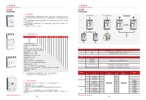
9493表 1表 2表 3二、产品型号及含义系列塑壳断路器1、周围空气温度上限不超过+40℃,下限值不低于-5℃,24h内平均温度不超过+35℃。
2、空气相对湿度:≤95%。
3、海拔高度不超过2000m,高于2000m需降容使用。
4、污染等级:3 级。
周围空气中无爆炸危险、且无腐蚀金属和破坏绝缘的气体和导电尘埃。
5、安装类别:III。
6、断路器的“1,3,5,N1” 端子接电源,“2,4,6,N2” 端子接负载,不可反接。
7、断路器的安装面应与水平面垂直。
断路器基本安装方式为垂直安装,电源端在上方,负载端在下方,亦可横向安装。
H UM8系列塑壳断路器(以下简称断路器)适用于交流 50Hz,额定电压至690V,额定电流至1250A的电力系统中,用来分配电能和保护电力系统免受过载 、短路、欠电压等故障的危害,也可用来控制电动机不频繁的操作。
电子式脱扣器和智能式脱扣器保护特性整定精确、方便。
智能式脱扣器具有串行通讯接口,可满足通讯组网的“四遥”要求。
全系列可带独特的“过载报警不脱扣”功能,保障供电连续性,满足GB 50054第6.3.6条的要求。
全系列断路器可适用于隔离。
符 合标准:GB/T 14048.2、IEC 60947-2注:(1)湿热型断路器(TH型)能耐受潮湿空气、盐雾、油雾、霉菌的影响。
(2)新能源专用产品(EN)周围空气湿度范围:-40~70℃。
系列塑壳断路器一、适用范围三、正常工作条件系列塑壳断路器系列塑壳断路器9695续表 4四、主要技术性能指标8、断路器在不同环境下的降容系数,见下表a 表 (a)()注:以各种环境温度条件下,实测断路器进出线端温度达到110℃为基准。
海拔超过适用工作环境的2000m,断路器的电气性能可参照下表修正,海报降容系数表,见下表(b)表 (b)表 4*飞弧距离为零的需在订货时注明。
10,16,20,25,32,40,50,6316,25,32,40,50,63,80,100100,125,150,160,175,200,225,2504333433310/5-85/85125/12510/5-125/125200/20010/5-85/85125/12510/5-125/125200/2008*飞弧距离为零的需在订货时注明。
AIMS Power PWRINV1 50W 直流到交流电源转换器说明书

DC TO AC POWER INVERTERPWRINV150W INSTRUCTION MANUALSAVE THIS MANUALYou will need the manual for the safety warnings and precautions, assembly instructions, operating and maintenance procedures, parts list and diagram. Keep your invoice with this manual. Write the invoice number on the inside of the front cover. Keep the manual and invoice in a safe and dry place for future reference.Basic Operation•Make sure that you choose the right operating voltage for both input and output of the inverter.•When unpacking, make sure that the inverter is in good condition. If any parts are missing or broken, please call AIMS Power, Inc. at the number found on the warranty card.•Place the power inverter on a flat surface. Make sure it has adequate ventilation and is not in direct sunlight. Fasten the inverter securely to the surface, using screws or some othermeans. If holes are to be drilled, follow safe, proper installation techniques.•Before you connect the battery cables, make sure the power switch is in the off position.Connect Red (+) battery cable to Red (+) inverter terminal. Connect Black (-) battery cable to Black (-) inverter terminal. Connect Red (+) battery cable to Red (+) battery terminal. Connect Black (-) battery cable to Black (-) battery terminal. Alligator clamp cables may be used but only to connect to the battery. Do not use clamps on inverter terminals. Alligator clamps are not a permanent solution. You may see a spark during connection.•Connect the ground cable to an earth ground, such as a metal water pipe or to the vehicle ground when used in a vehicle if the inverter includes a ground port.•Turn the power switch to the on position, which is located on the front of the inverter. The green LED light will confirm that AC power is present.•Before plugging the equipment into the inverter, make sure the equipment AND the inverter are off. Turn inverter on first, then turn on the equipment.•The power inverter can be used either while the engine is running or off.Warnings•Unplug the inverter when it is not in use.•If the AC inverter makes a beeping sound, turn off the equipment, unpl ug the inverter and restart the vehicle’s engine. The beeping sound is simply the low-battery warning, which indicates that the voltage of your battery is getting low. If you do not re-start your engine and continue operating the inverter, the inverter will automatically shut off, leavingyour vehicle's battery at about 10. 5 VDC. This will allow you to start your engine and resumeoperation of the inverter. It also reduces the fear of being stranded with a dead battery(dependent on health of battery).•This device should only be serviced by a qualified technician. This item does not have any serviceable parts.•Prevent body contact with grounded surfaces such as pipes, radiators, ranges, and refrigerator enclosures during installation.•Do not operate the inverter if under the influence of alcohol or drugs. Read warning labels on prescriptions to determine if your judgement or reflexes are impaired while taking drugs. Ifthere is any doubt, do not operate the inverter.•People with pacemakers should consult their physician(s) before using this product.Electromagnetic fields in close proximity to a heart pacemaker could cause interference to or failure of the pacemaker.•Keep children away. Children must never be allowed in the work area. Do not let them handle machines, tools, or extension cords.•Store idle equipment. When not in use, inverter must be stored in a dry location to prevent rust. Always lock up tools and the inverter and keep out of reach of children.•Size the inverter properly. Size the inverter for the surge rating of your equipment. The inverter’s continuous rating should be MORE than the surge rating of your equipment.Example: Power tool runs at 1500 watts but surges at 2500 watts. You should use an inverter >3000 watts.•Keep the inverter well-ventilated. Do not place any objects on top of or next to the inverter or allow anything to cover the cooling fans; doing so can cause the inverter to overheat,causing a potential fire hazard and/or damage to the inverter. Leave adequate ventilationspace underneath the inverter as well; thick carpets or rugs can obstruct air flow, causing the inverter to overheat.•Avoid unintentional starting. Be sure the switch is in the OFF position when not in use and before plugging in any appliance.Note: Performance of this unit may vary depending on the available battery power or appliance wattage.Warning: The warnings, cautions, and instructions discussed in this instruction manual cannot cover all possible conditions and situations that may occur. It must be understood by the operator that common sense and caution are factors which cannot be built into this product, but must be supplied by operator. Guard against electric shock. Do not open the metal case; risk of electric shock.Battery Use•To avoid over-discharging your vehicle battery, we recommend running your engine for 10-20 minutes to recharge the vehicle's battery if battery voltage drops <11V.•To properly size your battery, use the following formula: Volts * Amps = Watts or Watts/Volts = Amps. Example: 1000 Watt inverter / 12 volts DC = 83.3 DC amps. In this example, you willneed 83.3 amps to power a 1000 Watt load for 1 hour. If you need to power 1000 watts for 2 hours you will need 83.3 * 2 = 166.66 DC amps available. A 100 Amp hour battery will giveyou 100 amps / 166.66 = .6 hours so you will need two batteries if using 100 amp battery.This is if you fully deplete your batteries. We do NOT recommend fully depleting yourbatteries. This is just an example. Your power requirements may be different.•If you choose to use a female 12 Volt DC adapter for your inverter or to the inverter make sure wire size is correct.•IF YOU CONNECT THE WIRES TO THE INCORRECT TERMINALS, YOU WILL REVERSE THE POLARITY AND DAMAGE THE INVERTER.•REVERSED POLAR ITY WILL INSTANTLY VOID THE WARRANTY OF YOUR INVERTER, SO BE CAREFUL TO CONNECT YOUR INPUT WIRES PROPEPLY.•If you choose to operate a battery charger to replenish your battery’s voltage, be sure to check with charger manufacture before damaging the charger.•CONNECTING THE INVERTER’S DC INPUT TO A BATTERY CHARGER WILL VOID THE WARRANTY, AND MAY DAMAGE THE INVERTER.•Make sure that the battery voltage does not exceed 15 volts DC.•CONNECTING THE INVERTER TO A DC POWER SOURCE GREATER THAN 15 VDC WILL VOID THE WARRANTY, AND MAY DAMAGE THE INVERTER.CablesWe recommend that you refrain from using battery cables longer than 12 feet between the DC power source and the DC input of the inverter. Longer battery cables on the DC input will create a voltage drop which results in a reduction of efficiency and output. If you require more than 12 feet, use a bigger cable. We recommend using an extension cord between the AC output and AC appliance. You may use up to 100ft, high quality extension cord. A longer cord may result in reduced output. See Specifications chart for recommended battery cable size.Measuring the AC VoltageThe output waveform of the inverter is a MODIFIED SINE WAVE. If you choose tomeasure the AC output voltage, you must use a TRUE RMS MULTI METER. Using any other type of voltage measuring device will result in an AC voltage reading of 10 to 30 volts lower than actual voltage. When using a true RMS multi meter, you will get an accurate reading.SAFETY PRECAUTIONS•Do not open the case of the inverter. The high voltage inside the unit is the same type of power as your electrical outlets at home.•Do not let the cord of the inverter, or any appliance cord get wet. If you are operating the inverter in a moving vehicle, we recommend that you secure the inverter to prevent it fromshifting around while the vehicle is moving.•Do not operate this inverter in or around water. Water can damage the inverter, and water damage is not covered under warranty. Also, do not operate the inverter with wet hands. The AC voltage of the unit makes it an electrical shock hazard if operated with wet hands.•Allow at least 12 inches of clearance around the Inverter for air flow. Ensure the ventilation openings on the rear and bottom of the unit are not obstructed.•Do not connect the inverter directly to another AC power source. Damage may result, and such damage will void the inverter warranty.•Know the wattage requirements of your appliance. Use only those appliances which are limited by the capacity of this unit.•Use common sense. This device produces power just like your wall outlets at home and should be treated seriously. Keep it away from children.•Reversed polarity of AC power outlet LINE /NEUTRAL will void the warranty.•If there is anything wrong with the inverter, disconnect all of the power and contact technical support.TROUBLESHOOTINGIf the Inverter does not appear to be functioning properly, check the following possible causes:•Poor contact: Clean contact parts thoroughly.•If the low battery alarm sounds, this means the input voltage is too low and battery needs to be recharged.•If you are getting a low output voltage, try reducing the load to minimize watts. You may have overloaded the inverter. Reduce your load. Also, keep input voltage above 10.5 volts tomaintain a constant flow of power.•If you are not getting any power output, turn the power switch Off and On again, until the green power light comes on. Your devices may draw too much power to operate them. Theinverter may be in thermal shutdown. Let it cool down and make sure there is adequateventilation around the unit.•If the green light turns red one of the following has happened:A.input voltage is too lowB.input voltage is too highC.short circuitD.inverter is close to overload•Battery voltage is too low: Start the engine to recharge the battery. Replace or recharge battery if needed.•Shuts down on overload: Reduce the wattage of your load.•Thermal shutdown: Under heavy loads for extended period, the inverter will shut down to prevent damage from excess heat. Simply reduce your load and allow theInverter to cool down.•Low-battery shutdown: Recharge your battery and resume operation.Very little maintenance is required to keep your inverter operating properly. You should disconnect input power first and then clean the exterior of the unit periodically with a dry cloth to prevent accumulation of dust and dirt. At the same time, tighten the screws on the DC input terminals.PLEASE READ THE FOLLOWING CAREFULLYNeither the manufacturer nor distributor makes any representation or warranty of any kind to the buyer that he or she is qualified to make any repairs to the product or that he or she is qualified to replace any parts of the product. In fact, the manufacturer and/or distributor expressly states that all repairs and parts replacements should be undertaken by certified and licensed technicians and not by the buyer. The buyer assumes all risk and liability arising out of his or her repairs to the original product or replacement parts thereto, or arising out of his or her installation of replacement parts thereto.WARRANTYAIMS Corp., Inc. dba AIMS Power Warranty Instructions:This product is designed using the most modern digital technology and under very strict quality control and testing guidelines. If, however, you feel this product is not performing as it should, please contact us:**************************(775)359-6703We will do our best to resolve your concerns. If the product needs repair or replacement, make sure to keep your receipt/invoice, as that will need to be sent back along with the package and RMA# prepaid to AIMS. You have a full 1 year warranty from date of purchase.This warranty is valid worldwide with the exception that freight and duty charges incurred outside the contiguous 48 United States will be prepaid by customer.Except as provided above, AIMS makes no warranty of any kind, express or implied, including without limitation the implied warranties of merchantability and fitness for a particular purpose. In no event shall AIMS be liable for indirect, special or consequential damages. This warranty only applies to AIMS Power branded products. All other name brand products are warranted by and according to their respective manufacturer. Please do not attempt to return non-AIMS Power branded products to AIMS Power.For additional products such as:-Modified sine wave inverters-Pure sine wave inverters-Low Frequency Inverters-Solar Charge Controllers-Micro Grid Tied Inverters-Inverter Chargers and Automatic transfer switches-Converters DC-DC-Custom cut cables-Batteries-Solar Panels & RacksPlease visit our web site: Tofindoutwheretobuyanyofourproducts,youmayalsoe-mail:************************ (775)359-6703.。
SmartPro 550VA 线交互UPS(6口插座、AVR、USB)产品介绍说明书
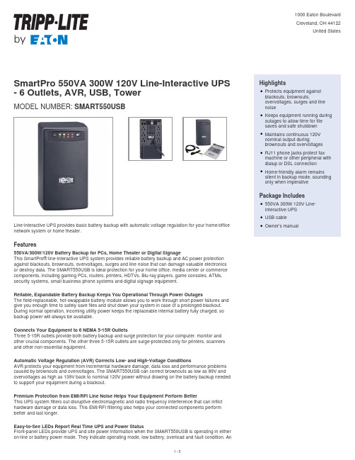
SmartPro 550VA 300W 120V Line-Interactive UPS - 6 Outlets, AVR, USB, TowerMODEL NUMBER:SMART550USBLine-interactive UPS provides basic battery backup with automatic voltage regulation for your home/office network system or home theater.Features550VA/300W/120V Battery Backup for PCs, Home Theater or Digital SignageThis SmartPro® line-interactive UPS system provides reliable battery backup and AC power protection against blackouts, brownouts, overvoltages, surges and line noise that can damage valuable electronics or destroy data. The SMART550USB is ideal protection for your home office, media center or commerce components, including gaming PCs, routers, printers, HDTVs, Blu-ray players, game consoles, ATMs, security systems, small business phone systems and digital signage equipment.Reliable, Expandable Battery Backup Keeps You Operational Through Power OutagesThe field-replaceable, hot-swappable battery module allows you to work through short power failures and give you enough time to safely save files and shut down your system in case of a prolonged blackout. During normal operation, incoming utility power keeps the replaceable internal battery fully charged, so backup power will always be available.Connects Your Equipment to 6 NEMA 5-15R OutletsThree 5-15R outlets provide both battery backup and surge protection for your computer, monitor and other crucial components. The other three 5-15R outlets are surge-protected only for printers, scanners and other non-essential equipment.Automatic Voltage Regulation (AVR) Corrects Low- and High-Voltage ConditionsAVR protects your equipment from incremental hardware damage, data loss and performance problems caused by brownouts and overvoltages. The SMART550USB can correct brownouts as low as 89V and overvoltages as high as 139V back to nominal 120V power without drawing on the battery backup needed to support your equipment during a blackout.Premium Protection from EMI/RFI Line Noise Helps Your Equipment Perform BetterThis UPS system filters out disruptive electromagnetic and radio frequency interference that can inflict hardware damage or data loss. This EMI/RFI filtering also helps your connected components perform better and last longer.Easy-to-See LEDs Report Real Time UPS and Power StatusFront-panel LEDs provide UPS and site power information when the SMART550USB is operating in either on-line or battery power mode. They indicate operating mode, low battery, overload and fault condition. An HighlightsProtects equipment againstblackouts, brownouts,overvoltages, surges and linenoiseqKeeps equipment running during outages to allow time for filesaves and safe shutdownqMaintains continuous 120Vnominal output duringbrownouts and overvoltagesqRJ11 phone jacks protect faxmachine or other peripheral with dialup or DSL connectionqHome-friendly alarm remainssilent in backup mode, sounding only when imperativeqPackage Includes550VA 300W 120V Line-Interactive UPSqUSB cableqOwner’s manualqSpecificationsaudible alarm will sound in case of low battery, excessive load and fault condition.HID-Compliant USB Port Allows for Automatic ShutdownsThis port connects the SMART550USB to a computer running free downloadable PowerAlert® software to enable safe unattended system shutdown in case of a prolonged power failure. USB cable is included.Includes Power Protection for your Phone and Network LinesDual RJ11 jacks protect your modem, fax machine or other equipment against surges over a single telephone or network line.Tower Form Factor for Easy Placement in Your Workspace or Media CenterThe long-lasting plastic housing fits easily on a desktop, shelf or anywhere else convenient to your workstation or home theater. The six-foot (1.8-meter) power cord with right-angle NEMA 5-15P plug connects to a properly grounded AC wall outlet.© 2023 Eaton. All Rights Reserved. Eaton is a registered trademark. All other trademarks are the property of their respective owners.。
茂笋LED08-20BY4-US 7.6W AC DC 转换器说明书
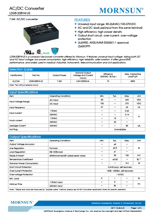
7.6W,AC/DC converterRoHSFEATURES●Universal input range:85-264VAC/100-370VDC●AC and DC dual-use(input from the same terminal)●High efficiency,high power density●Output short circuit,over-current,over–voltage protection●UL60950,ANSI/AAMI ES60601-1approval (2xMOPP)LD08-20BY4-US is a compact size power converter offered by Mornsun.It features universal input voltage,taking both DC and AC input voltage,low power consumption,high efficiency,high reliability,safer isolation.It offers good EMC performance,and widely used in medical,industrial,instruments,telecommunication and civil applications.Selection GuideCertification Part No.Output PowerNominal Output Voltage and Current(Vo/Io)Efficiency (230V AC,%/Typ.)Max.CapacitiveLoad*(µF)UL/CSALD08-20BY4-US7.6W3.8V/2000mA743000Note:*Test without external circuit.Input SpecificationsItemOperating Conditions Min.Typ.Max.Unit Input Voltage Range AC input 85--264VAC DC input100--370VDC Input frequency 47--63HzInput current 115V AC ----0.24A 230V AC ----0.14Inrush current 115V AC --15--230V AC --30--Leakage Current 264V AC----80uA Hot PlugUnavailableOutput SpecificationsItemOperating ConditionsMin.Typ.Max.UnitOutput Voltage Accuracy --±2--%Line Regulation Full load --±0.5--Load Regulation 0%-100%load--±1--Ripple &Noise*20MHz bandwidth (peak-peak value)--50100mV Temperature Coefficient --±0.02--%/℃Stand-by Power Consumption ----0.3W Short Circuit Protection Continuous,self-recovery Over-current Protection 130%-300%Io,self-recoveryOver-voltage Protection ≤6VDCMin.Load 0----%Hold-up Time115V AC input --5--ms230V AC input--40--Note:*Ripple and noise are measured by “parallel cable”method,please see AC-DC Converter Application Notes for specific operation.General SpecificationsItemOperating Conditions Min.Typ.Max.Unit Isolation Voltage Input-outputTest time:1min4000----VAC Operating Temperature-25--+70℃Storage Temperature -40--+85Storage Humidity ----95%RHWelding Temperature Wave-soldering 260±5℃;time:5-10s Manual-welding360±10℃;time:3-5sSwitching Frequency --65--kHz Power Derating -25℃to 0℃ 2.0----%/℃+50℃to +70℃ 2.5----Safety Standard UL60950/ANSI/AAMI ES60601-1Safety Certification UL60950/ANSI/AAMI ES60601-1Safety Class CLASS I IMTBFMIL-HDBK-217F@25℃≥300,000hPhysical SpecificationsCasing Material Black flame-retardant and heat-resistant plastic (UL94V-0)Package Dimensions 45.70*25.40*15.20mm Weight29g(Typ.)Cooling methodFree airconvectionEMC SpecificationsEMICE CISPR11/EN55011CLASS B RE CISPR11/EN55011CLASS BEMSESD IEC/EN61000-4-2Contact ±6KV/Air ±8KV Perf.Criteria B RS IEC/EN61000-4-310V/m perf.Criteria A EFTIEC/EN61000-4-4±2KVperf.Criteria B SurgeIEC/EN61000-4-5line to line ±1KV perf.Criteria B CSIEC/EN61000-4-610Vr.m.s perf.Criteria A Voltage dips,shortinterruptions and voltage variations immunityIEC/EN61000-4-110%,70%perf.Criteria BProduct Characteristic CurveNote:①Input voltage should be derated based on temperature derating when it is 85-100VAC/240-264VAC/100-120VDC/340-370VDC;②This product is suitable for use in natural air cooling environments,if in a closed environment,please contact our company’s FAE.Design Reference1.Typical application circuitA C (L)+Vo-VoA C (L )A C (N )A C (N )C 1C 2L O A DF U S E A C -D CM O VN T C2134Fig.1:Typical application circuitModel FUSEMOV NTC C1(µF)C2(µF)LD08-20BY4-US2A/250V,slow fusingS14K3005D-91220Note:Output filtering capacitor C2is electrolytic capacitor,it is recommended to apply electrolytic capacitor with high frequency and low resistance.Forcapacitance and current of capacitor please refer to manufacture’s datasheet.Capacitor voltage reduced to at least 80%.C1is ceramic capacitor,which is used to filter high-frequency noise.2.For more information please find application notes on Dimensions and Recommended LayoutNote:1.Packing information please refer to Product Packing Information which can be downloaded from .Packing bag number:58000155;2.Unless otherwise specified,parameters in this datasheet were measured under the conditions of Ta=25℃,humidity<75%with nominal input voltage and rated output load;3.All index testing methods in this datasheet are based on our Company’s corporate standards;4.We can provide product customization service,please contact our technicians directly for specific information;5.Products are related to laws and regulations:see "Features"and "EMC";6.Our products shall be classified according to ISO14001and related environmental laws and regulations,and shall be handled by qualified units.Mornsun Guangzhou Science &Technology Co.,Ltd.Address:No.5,Kehui St.1,Kehui Development Center,Science Ave.,Guangzhou Science City,Luogang District,Guangzhou,P .R.China Tel:86-20-38601850-8801Fax:86-20-38601272E-mail:***************。
ABB电源转换器说明书
1ABBFeaturesRated output voltage 48 V DCOutput voltage adjustable via front‑face rotary potentiometer “OUTPUT Adjust” Rated output current 5 A Rated output power 240 WSupply range 115/230 V AC (90‑132 V AC, 180‑264 V AC, 210‑375 V DC), auto select Typical efficiency of 90 %Low power dissipation and low heatingFree convection cooling (no forced cooling with ventilators) Ambient temperature range during operation ‑40...+70 °C Open‑circuit, overload and short‑circuit stable Integrated input fuseLEDs for status indicationApprovalsA UL 508, CAN/CSA C22.2 No.14Approval refers to rated input voltage U inH ANSI/ISA‑12.12 (Class I, Div. 2,hazardous locations)H UL 60950, CAN/CSA C22.2 No.60950Approval refers to rated input voltage U in DGOST ECCC Approval refers to rated input voltage U inMarksa CE bC‑TickOrder dataApplicationThe primary switch mode power supply offers two voltage input ranges. This enables the supply with AC or DC. Furthermore it is equipped with two generous capacitors, which ensure mains buffering of at least 30 ms (at 230 V AC). That is why the devices can be used worldwide also in high fluctuating networks and battery‑powered plants.Operating modeBy means of the potentiometer …OUTPUT Adjust“ the output voltage can be adjusted within a range of 47 to 56 V DC. Thus, the power supply can be optimally adapted to the application, e.g. compensating the voltage drop caused by a long line length.The green LED …OUTPUT OK“ is lightening during proper operation.The red LED …OUTPUT LOW“ is lightening when the output voltage is too low. Switch …single/parallel“ for selection of single or parallel operation.a OUTPUT L+, L+, L‑, L‑:terminals ‑ output b INPUT L, N, PE:terminals ‑ inputc OUTPUT OK: green LED ‑ output voltage OK OUTPUT LOW: red LED ‑ output voltage too low OUTPUT Adjust:‑djustment of the output single/parallel:InstallationThe switch mode power supply can be snapped on a DIN railaccording to IEC/EN 60715 as shown in the accompanyingpicture. For that the device is set with its mounting rail slideon the upper edge of the mounting rail and locked by lifting itdownwards.DemountingRemove the switch mode power supply as shown in theaccompanying picture. For that the latching lever is pulleddownwards by means of the screwdriver. Alternatively youcan press the unlock button to release the device. Then inboth cases the device can be unhinged from the mountingrail edge and removed.The devices have to be mounted horizontally with the i nputt erminals on the bottom. In order to ensure a sufficientc onvection, the m inimum distance to other modules should notbe less than 25 mm in vertical and horizontal direction.Electrical connectionConnect the input terminals L and N. The protective earth conductor PE must be connected. Thei nstallation must be executed acc. to EN 60950, provide a suitable disconnecting device (e. g. linep rotection switch) in the supply line. The input side is protected by an internal input fuse.Rate the lines for the maximum output current (considering the short‑circuit current) or provide as eparate fuse protection. We recommend to choose the cable section as large as possible in order tominimize voltage drops. Observe the polarity. The device is overload, short‑circuit and open‑circuit proof.The secondary side of the power supply unit is electrically isolated from the input and internally notearthed (SELV) and can therefore be earthed by the user according to the needs with L+ or L‑ (PELV).ABB 23ABBConnection diagramL+, L‑Output voltage L, NInput voltage No function not connected PE Protective earthSafety instructions and warningsThe device must be installed by qualified persons only and in accordance with the specific nationalr egulations (e.g., VDE, etc.). The devices are maintenance‑free chassis‑mounted units.Disconnect system from supply network!Before any installation, maintenance or modification work: Disconnect the system from the supplyn etwork and protect against switching on.Before start of operation:Attention! Improper installation/operation may impair safety and cause operational difficulties ord estruction of the unit. Before operation the following must be ensured: Connect to main according to the specific national regulations.Power supply cables and unit must be sufficiently fused. A disconnecting device has to be provided for the power supply to disengage unit and supply cables from supply mains if required. The protective earth conductor must be connected to the terminal PE (Protection class I)The secondary side of the power supply unit is not earthed and can be earthed by the user according to the needs with L+ or L‑.Rate the output lines for the output current of the power supply and connect them with the correct polarity.In order to ensure sufficient air‑cooling the distance to other devices has to be considered.In operation:Do not modify the installation (primary and secondary side)! High current! Risk of electric arcs and electric shocks (danger to life)!Risk of burns: Depending on the operation conditions the enclosure can become very hot.The internal fuse is not user‑replaceable. If the internal fuse blows, most probably the device isd efective. In this case, an examination of the switch mode power supply by the manufacturer is n ecessary.Attention! High voltage! Danger to life!The power supplies contain components with high stored energy and circuits with high voltage! Do not introduce any objects into the unit, and do not open the unit. With some units of this range theo utput is capable of providing hazardous energy. Ensure that the service personnel is protected againstinadvertent contact with parts carrying energy.2C D C 272 022 F 0b 08Technical dataData at T a = 25 °C, U in= 230 V AC and rated values, unless otherwise indicatedABB 45ABB6ABB Technical diagramsOutput behaviourUI out [A]Characteristic curve of output at T a = 25 °CThe switch mode power supply CP‑E 48/5.0 is able to supply at 48 V DC output voltage andat an ambient temperature of:≤ 60 °C a continuous output current of approx. 5 Aat ambient temperatures of:60 °C < T a ≤ 70 °C the output power has to be reduced by 2.5 % per °C temperature increase.If the switch mode power supply is loaded with an output current > 5 A, the operating point is passing through the U/I characteristic curve shown.Temperature behaviour2CDC27217F211Characteristic curve of temperature at rated load7ABBDimensionsin mmCP-E 48/5.0Further DocumentationYou can find the documentation on the internet at /lowvoltage R Control Products RPower Supplies2C D C 272 003 F 0b 08As part of the on‑going product improvement, ABB reserves the right to modify the characteristics of the products described in this document. The information given is non‑contractual.For further details please contact (/contacts) the ABB company marketing these products in your country.D o c u m e n t n u m b e r : 2C D C 114 063 D 0201 (09/20011ABBABB STOTZ-KONTAKT GmbHEppelheimer Strasse 82, 69123 Heidelberg, Germany Postfach 10 16 80, 69006 Heidelberg, GermanyInternet /lowvoltage R Control ProductsContact: /contacts R Low Voltage Products and Systems。
SL500系列单输出DC DC转换器说明书
FeaturesHow to OrderAgency ApprovalsMilitary Grade Environmental Screening Notes:See “Guide to Operation” for full detailsNotes:Standard unit has pins out the top with 6-32 THD inserts,written as SL500SI/28-270• Input Range from 200Vdc to 400Vdc • No Derating from -55 C to +100 C • Efficiency: Up to 91%• Parallelable• Synchronizable• Power Density: Up to 87W / in�• Non-latching Overtemperature Protection • Fixed Frequency Power Conversion • Latching Output Overvoltage ProtectionSL 500 S I / 28 - C (270)SeriesTotal Output Power Single Output OptionsI - Unscreened M - Screened Output Voltage OptionsC - Thru Hole Inserts (0.140 DIA) I - Metric Inserts (M3)Input Voltage100% Environmental Screening for Military Versions Meets MIL – Standards: MIL – STD – 454 P4855 – 1A MIL – STD – 704D MIL – STD – 810E MIL – S – 901C MIL-STD- 461F with companion filter The SL500 converter is a standalone, 91% efficient COTS converter in a standard 2.4” x 4.6” x 0.52” full brick package.Protection features include overvoltage, overcurrent, overtemperature, and short circuit protection.The converter is parallelable for higher power require-ments and synchronizable for noise sensitive systems. A 300 KHz fixed switching frequency aids in filtering of EMI. The SL500 EMI filter is third party qualified and meets Mil-Std-461F for conducted emissions.All “Mil” Grade units receive the following:Stabilization Bake :+125 C for 24 hours per Mil-Std-883, M1108, Condition B Temperature Cycling :10 cycles at -55 C to +125 C (transition period 36 minutes) per Mil-Std-883, M1010, Condition B Burn-in :160 hours at +85 C min.Final TestingModel Number (Unscreened)SL500SI/28 (270)SL500SI/24 (270)SL500SI/15 (270)SL500SI/12 (270)SL500SI/5 (270)SL500SI/3.3 (270)Nominal Output(Vdc)2824151253.3Output Current(Amps)17.920.925254040/powerconversionFor additional information, call 310.542.8561ore-mail:*******************Input Characteristics - 270Vdc InputOutput CharacteristicsInput VoltageBrown Out (75%) Full Load No Load Power Dissipation Inrush Current <20µS Duration Reflected Ripple Current Logic Disable Current (Sink)Logic Disable Power In Input Ripple Rejection (120HZ)Efficiency Up ToInput Transient Per MIL-STD-704D (Operating 100ms)EMIMIN200185TYP 27027302.86091UNITS Vdc Vdc W A A rmsmA W dB %MAX 4000.52Use Companion FilterNote: Output Ripple is measured with 1µF ceramic and 22µF low ESR Tantalum CapacitorSet Point Accuracy Load Regulation Line Regulation Ripple P-P (20MHz)Trim Range Remote Sense 12V , 15V , 24V , 28V3.3V , 5VOvervoltage Protection Current Sharing Transient Response 50-75% Load (0.2A/µS)Temperature Drift Long Term Drift Current Limit Short Circuit Current Turn-on Time (Power Input)Logic Turn-on Time Switching Frequency Sync Input Voltage Sync Input Frequency Sync Input Duty Cycle Turn-on OvershootMIN90110254.533015TYP 11250.010.0215090300MAX 1±0.3±0.231100.500.25135±83/3000.030.05140755.5360550.1UNITS % Vout % Vout % Vout % Vout % Vout Vdc Vdc % Vout % Iout / at Full Load% Vout / µSSetting Time to Within 1% Vout%Vout / C %Vout / 1KHrs%Iout %Iout Hiccup TypemS FL 270V mS FL 270VKHzVp-p KHz %% Vout500VdcSpecificationsTemperature CharacteristicsMechanical CharacteristicsOperating (Baseplate)Storage (Ambient)Over Temperature Shutdown Thermal Resistance (Case to Ambient)MIN-55-55TYP +1055.71MAX +100+125+110UNITS C CC / Auto RecoveryC / WInput to Output Output to Base-plate Input to Base-plate Insulation Resistance (Measured at 50 VDC)Input to Output CapacitanceMIN1000500100050TYP 0.003MAX UNITS Vdc Vdc Vdc MohmµFWeight Size Volume Mounting (STD)ConstructionTYP7.62.4 x 4.6 x 0.5261 x 116.9 x 13.25.7494UNITS oz in mm in�cm�Threaded, #6-325 sided metal can, nickel plated cover, aluminum baseplateIsolation CharacteristicsCase drawingsCase Drawingsinch mmA 4.60116.9B 2.4061.0C .5213.2D 2.00050.80E .205.1F .205.1G .3759.53H 4.200106.68J .5012.7K .40010.20L .70017.8M 1.00025.40N 1.40035.60P.0401.02R .0802.03Standard ModelC OptionThru hole inserts (0.140 DIA)Model number written as SL500SI/28-C (270)Tolerances:Material: Mounting: 6-32 THD inserts are provided in baseplate Metric: M3 insertsInches mm x.xx = ±0.03x.xxx = ±0.015x.xx = ±0.4x.x = ±0.8Pin = Brass (Solder Plating)Baseplate = Aluminum 5050-H32Case = SteelFinish = Nickel PlatingPin placement on top of unitTOP VIEW(MARKING SURFACE)KLMNJB FHE DA12345678109P DIA ±0.005B A S E P L A T EINPUT PINSOUTPUT PINSG MINCR DIA ±0.005B A S E P L A T EG MINP DIA ±0.005CCharacteristicsCharacteristicsIX. TTL Turn OnIII. Ef ficiency vs. Input VoltageII. Efficiency vs. Output Power I. Input Voltage vs. Output PowerVI. Input Transient ResponseV. Load Transient ResponseIV. Output Voltage RippleVII. Input Inrush CurrentVIII. Input Current RippleX. TTL Turn OffXI. Turn OnXII. Turn OffO u t p u t P o w e r (%)Input Voltage VDC E f fi c i e n c y (%)E f fi c i e n c y (%)10090807017017518018540020406080100556065707580859095Output Power (%)Input Voltage VDC9492908886848280787620024028032036040050m V /d i v500m V /d i v5A /d i vTime: 2µS/divBandwidth: 20MHzV in = 270Vdc I out = 17.9A V out = 28VTime: 400µS/divV in = 270Vdc V out = 28VI out = 17.9A V out = 28V200m V /d i v100V /d i vTime: 400µS/div100V /d i v10A /d i vV in = 270Vdc I out = 17.9A V out = 28VTime: 10µS/div 2A /d i vTime: 2µS/div V in = 270Vdc I out = 17.9A V out = 28VV in = 270Vdc I out = 17.9A V out = 28VV in = 270Vdc I out = 17.9A V out = 28VV in = 270Vdc I out = 17.9A V out = 28VV in = 270Vdc I out = 17.9A V out = 28V Time: 400µS/divTime: 200µS/divTime: 20mS/divTime: 20mS/div2V /d i v5V /d i v5V /d i v5V /d i v100V /d i v5V /d i v100V /d i v10V /d i vFor example, if the DC/DC converter in Figure 1a is a50W unit (5VDC @ 10 Amps) with output load regulationspecified at 0.2%; the connection as shown will degradeload regulation by a factor of 10. In this example, the 4feet of #14 AWG wire used to connect the converteroutput to the load, has a total line resistance of 10mΩ(ignoring any contact resistance). For a 50W, 5 VDCoutput converter, the drop across the lead resistance willbe 100 mV (10A x 0.010Ω) or 2% of the output. Thus,the converter is selected for 0.2% regulation, but thepower system layout achieves only 2.2%.This can be corrected by decreasing the distancebetween the converter output and load. If that is notpossible, using larger diameter wire (see Table 1), orPCB runs that have larger cross sectional area andshorter length will also reduce conductor resistance. Theuse of the converter’s remote sense capability will alsowork (see Remote Sense for more information on thisoption).General Application NotesThe most basic use of the power converter is shown inFigure 1. An input fuse is always recommended toprotect both the source and the power supply in theevent of failures. Slow-blow fuse is recommended with acurrent rating approximately 200% of the full load inputcurrent to the converter. Having a slow-blow type fusewill allow for the converter’s inrush charge at turn-on.The sense pins of the converters must be connected totheir corresponding output bus. Inherently, powerconverters will have some internal energy loss, which isdissipated in the form of heat through an aluminummounting surface. This surface must be cooled tomaintain a temperature below the maximum operatingtemperature.Wire Gage & Distance to LoadIf the resistance of the wire, printed circuit board runs orconnectors used to connect a converter to systemcomponents is too high, excessive voltage drop will resultbetween the converter and system components, degrad-ing overall system performance.The SL family of power converters, designed as militarygrade standalone power converters, can also be used ascomponents in complex power systems. The SL Seriesutilizes a high efficiency full bridge isolated DC to DCconverter which operates at 300 KHz constant frequency.The SL units are supplied in five sided metal case tominimize radiated noise. A number of protectionfeatures, as well as electrical and thermal derating ofinternal components per NAVSO P3641A guidelines andthe use of proven topology allow for high reliabilitythroughout an operating range of -55 C to +100 C. Inapplications where even greater reliability is required, theconverter can be screened to MIL-STD-883 upon#AWG91011121314151617181920CurrentResistance(mΩ/Foot)0.7920.9981.2611.5882.0012.5243.1814.0205.0546.3868.04610.13#AWG212223242526272829303132CurrentResistance(mΩ/Foot)12.7716.2020.3025.6732.3741.0251.4465.3781.21103.7130.9162.0Table 1/powerconversionFor additional information, call 310.542.8561ore-mail:*******************General Application Notes - con’tRemote sense pins, +S and -S have been provided on the SL Series converters for applications where precise load regulation is required at a distance from where the converter is physically located. If remote sensing is NOT required, these pins MUST be tied to their repective output pins (+S to +OUT, -S to -OUT, see Figure 2). If one or more of these sense pins are not connected to their respective output pins, the output of the unit will not regulate to within specification and may cause high output voltage condition.Remote On / OffNOTE: High IR drops between the converter and load may cause converter parameters, such as output voltage accuracy, trim range, etc., to appear to be out of specification. High IR drops on input lines may cause start up problems (voltage at the input pins below the input range of the converter). Obviously, any connections made to the power distribu-tion bus present a similar problem. Poor connections (such as microcracking around solder joints) can cause serious problems such as arcing. Contact resistance must be minimized. Proper workmanship standards must be followed to insure reliable solder joints for board mount converters. Terminal strips, spade lugs and edge connectors must be free of any corrosion, dust or dirt. If parallel lines or connections are available for routingconverter output currents, they should be utilized. Remote SenseFigure 2DO NOT connect sense pins to any pin other than their respective output pins or permanent damage will occur. DO NOT connect sense pins to any load other than the same load the output pins are connected to or permanent damage may occur.Remote turn ON / OFF (TTL Pin) is an additional featureto the SL Series. This feature is especially useful inportable/mobile applications where battery powerconservation is critical. The voltage level at the TTL pinis referenced with respect to the converter’s –VIN Input.When the TTL pin is pulled to less than 1.0V with respectto the –VIN pin. Via either an open collector (see Figure3) or a mechanical switch with a 0.5mA capability, the converter shuts down. An optocoupler can also be usedIF the TTL Signals need to be referenced from the outputside. If the TTL pin is left floating the unit remains on.When multiple units are tied to a central switch com-mand, a series resistor of 200 Ohms to each TTL pin isrecommended to increase noise immunity.Figure 3 Output TrimThe output trim pin has been supplied on the SL familyto provide output voltages other than the nominal fixedvoltage. Output voltage can be increased or decreased(+10% Max, -10% Min) by simply connecting a resistorbetween the trim pin and the –Output return pin or the+Output pin respectively (see Figure 4).Figure 4Output Trim - con’tThe value of the resistors required to Trim Hi is shown in the Table 2. The external resistor is connected between the Trim Pin and the Output Return Pin at the power supply (use standard value 1% resistor closest to the table value). Trimming the output voltage too high may activate the over voltage protection circuitry. The value of resistor required to Trim Lo is shown in Table 2.The external resistor is connected between the Trim Pin and the +Output Pin at the power supply (use standard value 1% resistor closest to the table value). A potentiometer can be substituted for the resistor to achieve a more precise output voltage setting. When trimming up or down, the maximum output current and/or maximum output power cannot be exceeded.15Vout110% Vout 108% Vout 106% Vout 104% Vout 102% Vout 100% Vout 98% Vout 96% Vout 94% Vout 92% Vout 90% Vout Volts16.5016.2015.9015.6015.3015.0014.7014.4014.1013.8013.50KΩ122.9153.9205.1309.9616.8OPEN107.846.225.715.49.124VoutVolts26.4025.9225.4424.9624.4824.0023.5223.0422.5622.0821.60KΩ224.0278.6369.8554.91165OPEN103.744.724.614.48.328VoutVolts30.8030.2429.6829.1225.5628.0027.4426.8826.3225.7625.20KΩ268.6331.8435.9650.61282OPEN110.649.528.918.612.43.3Vout110% Vout 108% Vout 106% Vout 104% Vout 102% Vout 100% Vout 98% Vout 96% Vout 94% Vout 92% Vout 90% Vout Volts3.633.563.503.433.373.303.233.173.103.042.97KΩ8.3010.414.021.443.3OPEN115.357.137.527.421.45VoutVolts5.505.405.305.205.105.004.904.804.704.604.50KΩ18.324.836.158.1134.0OPEN106.948.928.418.312.212VoutVolts13.2012.9612.7212.4812.2412.0011.7611.5211.2811.0410.80KΩ92.6117.1158.1241.7504.6OPEN100.744.424.914.98.80Table 2Military SpecificationsSpecification MIL-STD-704D MIL-STD-810EMIL-S-901CConditionInput TransientVibrationHumidityTemperature/AltitudeAccelerationTemperature ShockHigh Impact ShockMethod514.4507.3520.1513.4503.3Procedure1133Test ConditionTransients up to 500V for 0.1 sec (270Vdc input)Up to 30 gs, each axis for 1 hour95% humidity, non condensing for 10 days40 hours from -55°C to +71°C14 gs each axis-55°C to + 100°C (non-operating, one hour each cycle)5 foot hammer dropSeries OperationSynchronizationThe SL500 family of power converters may be arranged in a series operating mode to supply higher outputvoltages when required (see Figure 5). In this configura-tion, D1 and D2 are added to protect against the applica-tion of a negative across the outputs of the powerconverters during power up and power down. The two (or more) units do not need to have the same output voltage, but the output current supplied in this configura-tion will be limited to the lowest maximum output current of the modules used.Synchronization of switch-mode converters to a central system clock frequency is often essential in noise sensitive systems. The SL Series can be tied to the central clock that is referenced to -OUT (see Figure 7) by inputting a square wave clock signal which has a frequency amplitude and duty cycle within specifiedlimits. The SL Series converter’s internal synchonization circuit is triggered by rising edge of this clock waveform.DO NOT add any capacitance from the SYNC pin line to Ground.Parallel OperationThe SL500 converter family has the capability of being paralleled to drive loads of higher power than a single SL500 unit can handle. The PAR pin is supplied on the unit for this function (see Figure 6). If parallel operation of two or more units is removed, the following precau-tions must be followed:• Corresponding input and output leads or traces on each unit should be as equal in length and size aspractical. The more equivalent the leads are, the closer the unit sharing.• The PAR pins of all units should be tied together.The units do not have to be synchronized for parallel operation but may be if required (see Synchronization ). Or’ing diodes may be included in the positive output leads for true N + 1 redundant systems, but are not necessary. Local sensing should be used whenever possible to minimize noise on the +S and -S pins in parallel applications.Figure 6Parallel OperationSynchronization to External ClockOutput ripple and noise (sometimes referred to as PARDor “Periodic and Random Deviations”) can be defined as unwanted variations in the output voltage of a power supply. In switching power supplies, this output noise is seen as a series of pulses with a high frequency content and is therefore measured as a peak value (i.e., speci-fied as “peak-to-peak”).Ripple & NoiseRipple & Noise - con’tElectro Magnetic Filter (EMI) - SLF500The SL Series of power supplies are specified and tested in our factory with a 20 MHz bandwidth oscillo-scope / probe. Measurements taken by a scope set at higher frequencies (i.e. 300 MHz) may produce signifi-cantly different results due to noise coupling on to the probe from sources other than the power supply. Noise that is common to all output leads of a power converter with repect to the chassis is refered to as common mode noise. Noise that is apparent on one output lead with respect to the other output lead is referred to as differential mode noise. Common mode noise is produced in switching action. Martek Power, a brand of Cooper Bussmann, typically minimizes the level of output common mode noise by incorporating line to chassis ground capacitors (on input and output leads) into the power converters. In most cases, this issufficient to minimize the level of common mode noise. However, if further attenuation is required, additional line to chassis ground capacitance may be added by the customer at the system level. Martek Power noisespecifications (output ripple specifications) all reference the level of differential mode noise at a given bandwidth, not the level of common mode noise. The measurement of differential mode noise is detailed in the following paragraphs.Measurement TechniquesThe length of all measurement leads (especially the ground lead) should be minimized and the sense pins should be tied to their respective outputs (+SENSE to +OUTPUT, - SENSE to - OUTPUT). One inch or less from the output terminals, place a ceramic capacitor of 1µF and a 22µF low ESR Tantalum capacitor. Using an X1 scope probe with a 20 MHz bandwidth, we recom-mend measurement close to the capacitors. We do not recommend using the probe ground clip. Instead,replace it with connecting a short bus wire (generally 0.5 inches or less, making a loop at the end to place the probe in) to the negative and positive outputs on the backside of the connector. Place the tip of the probe on the +OUTPUT, and the ground ring (or ground band) on the -OUTPUT for a true ripple measurement (see Figure 8). Utilizing the probe ground ring (as opposed to a ground clip) will minimize the chance of noise coupling from sources other than the power supply.Figure 8Sense Tied Local+ SENSE + OUTPUT1” max.- SENSE- OUTPUT 1µF 22µFRipple and Noise Test Set-UpMaximum Allowable CapacitanceOutput Voltage3.3V 5V 12V 15V 24V 28VMax Capacitance15,000µF 15,000µF 5,000µF 5,000µF 3,000µF 3,000µFFor applications where electromagnetic interference is a concern, the SLF500, a passive input line filter may be installed at the input of the SL Series converters (see Figure 9). If output power greater than 500 watts are required, multiple SLF500 units will be necessary. For more details, consult the factory.Figure 9Table 3Ripple Reduction TechniquesIn applications where the output ripple of the converter is higher than desired, various techniques can beemployed to reduce output ripple and noise (PARD). One method is to add additional capacitance in parallel with the output leads of the converter (low ESR type tantalums or ceramic are recommended). This should substantially reduce PARD. See Table 3 for maximum allowable capacitance that may be added to the output leads.SLF500 SchematicSL500 Block DiagramINPUTVDCOUTPUTTTL ON/OFF/powerconversionEaton is a registered trademark. All other trademarks are property of their respective owners.Eaton1000 Eaton Boulevard Cleveland, OH 44122 United States © 2017 EatonAll Rights Reserved Printed in USA March 2017ore-mail:*******************。
电磁流量计转换器使用说明书
频率输出的范围为0~5000HZ,频率输出对应的是流量百分比,
频率输出的上限可调。用户可选0~5000HZ,也可选低一点的频率:如0~1000HZ或0~5000HZ等。
频率输出方式一般用于控制应用,因为它反映百分比流量,若用户用于计量应用,则应选择脉冲输出方式。
4.5.2脉冲输出方式:
图4.3.2接线端子图
4.3.2.2各接线端子标示含义如下:
POUT:
双向流量频率(脉冲)输出
ALM1:
上限报警输出
ALM2:
下限报警输出
COMM:
频率、脉冲、电流公共端(地线)
COMM:
频率、脉冲、电流公共端(地线)
IOUT:
流量电流输出(两线制电流输出)
IVIN
两线制24V电压输入
TRX+
通讯输入
■交流高频开关电源,电压适用范围:85VAC --- 250VAC;
■直流24V开关电源,电压适用范围:16VDC --- 36VDC;
■网络功能:MODBUS、HART(选配);
■中文、英文显示方式,(可定制其它语言);
■内部有三个积算器总量,可分别记录:正向总量、反向总量、差值总量。
1.2
■掉电时间记录功能,自动记录仪表系统电源间断时间,补算漏计流量;
脉冲输出方式主要用于计量方式,输出一个脉冲,代表管道流过一个当量的流体,如一个脉冲代表1L或代表1M3等。
脉冲当量分成:0.001L,0.01L,0.1L,1L,0.001 M3,0.01 M3,0.1 M3,1 M3。用户在选择脉冲当量时,应注意流量计流量范围和脉冲当量相匹配。对于体积流量,计算公式如下:
4.4.3励磁电流线
励磁电流线可采用二芯绝缘橡皮软电缆线,建议型号为RVVP2*0.12*250mm2。励磁电流线的长度与信号电缆长度一致。
AIMS Power纯正波电源电压转换器说明书
DC TO AC PURE SINE POWER INVERTERPWRI200012120SINSTRUCTION MANUALETL Listed to UL 458 and CSA 22.2 NO 107.1INTRODUCTIONThe AIMS Power pure sine inverter product line is used for back-up or mobile power. The pure sine product line is ideal for sensitive equipment and provides clean power, which is more efficient for back-up power applications. The power inverter transforms DC (direct current) electricity into AC (alternating current) power that can be used for running a wide variety of medium size devices up to 16 amps, using a battery. This inverter is perfect for providing mobile power in vehicles, RVs, boats, vans or buses.Read this instruction manual carefully and make sure your inverter is installed properly before using.WARNING AND SAFETY1.Keep manual for future reference.2.Do not put the inverter under direct sunlight or near a heating source.3.The case of the inverter will get hot when used. Do not allow flammablematerials to contact the inverter, such as clothing, sleeping bags, carpet or any other flammable materials. The heat from the inverter can damage these items.4.The power inverter is designed to be used with a negative ground electricalsystem! Don't use with positive ground electrical systems (the majority of modern automobiles, RVs, trucks and boats are negative ground).5.Do not disassemble the unit: it may cause fire or electric shock.6.This device should only be serviced by a qualified technician. This item does nothave any serviceable parts.7.Prevent body contact with grounded surfaces such as pipes, radiators, ranges,and refrigerator enclosures during installation.8.Do not operate the inverter if under the influence of alcohol or drugs. Readwarning labels on prescriptions to determine if your judgment or reflexes are impaired while taking drugs. If there is any doubt, do not operate the inverter. 9.People with pacemakers should consult their physician(s) before using thisproduct. Electromagnetic fields in close proximity to a pacemaker could cause interference to or failure of the pacemaker.10.Keep the inverter well-ventilated. Do not place any objects on top of or next tothe inverter or allow anything to cover the cooling fans; doing so can cause the inverter to overheat, causing a potential fire hazard and/or damage to theinverter. Leave adequate ventilation space underneath the inverter as well; thick carpets or rugs can obstruct air flow, causing the inverter to overheat.11.Avoid unintentional starting. Be sure the switch is in the OFF position when not inuse and before plugging in any appliance.12.Keep inverter away from children. Don't install the inverter where it is accessibleto children.13. The power inverter will output the same AC power as utility power, please treatthe AC outlets as carefully as you would your home AC outlets. Do not put anything other than an electrical appliance into the output terminal. It may cause shock or fire.14.Disconnect the battery and inverter when not in use.Note: Performance of this unit may vary depending on the available battery power or appliance wattage.Warning: The warnings, cautions, and instructions discussed in this instruction manual cannot cover all possible conditions and situations that may occur. It must be understood by the operator that common sense and caution are factors which cannot be built into this product, but must be supplied by operator. Guard against electric shock. Do not open the metal case; risk of electric shock.INVERTER FEATURES•Dual GCFI outlet•USB Port•LED protect indicator•LED power indicator•Easy push on/off switch•Remote port for on/off remote switch (optional)•Thermally controlled cooling fan•Low battery voltage warning/shutdown•High input voltage protection with automaticshutdown•Over load indicator•Short circuit protection•AC output short circuit protectionINSTALLATIONEnsure there is enough space for the installation, and the location should be meet the following requirements:1.Water should not access the inverter.2.The ambient temperature should be 32~104°F, and the preferred temperature is50-77°F. The lower the better in this range of ambient temperature.3.Do not mount the inverter upside down.4.We recommend mounting the inverter on something stable to prevent it frombouncing. Impact shock could result in damage to your unit. Be sure to use all four mounting screws for optimal stability. Mount in a location that can support the weight of the inverter.5.Allow 12 inches of space around the inverter to prevent objects from blockingthe vents and to provide enough air to circulate.6.Do not place objects that will block the vents. Allow enough air to circulate.7.Do not install the inverter in an environment with high dust, saw dust residue orother particles that may get sucked into the inverter increasing internaltemperature.8.There will be some electrical arcing or spark when the inverter connects with thebattery. Combustible materials such as gasoline, alcohol, etc. should not bearound the inverter.BATTERY1.The battery is designed to supply the inverter with DC input voltage and the ratedvoltage should be in accordance with the rated input voltage of the inverter. Any voltage exceeding the range of the input voltage of the inverter will cause the inverter to go into overload and could possibly damage the inverter. The battery should supply enough current for the load. The load is the amp or watt rating of the equipment being powered by the inverter. A small capacity battery cannot provide enough power for large electrical equipment. In this case, the battery will cause the inverter to go into under voltage protection because of the load put on the battery. A simple way to calculate the load or amps required from your battery is to divide watts of equipment by battery voltage. Due to the consumption of the inverter itself, the actual current will be about 10%more. For example, the voltage of lead acid battery is 12VDC, and load of the equipment is 1000W,therefore, the actual current needed from the battery is about 1000W / 12V = 83.3amps per hour. Add 10% for efficiency loss and you get 83.3 * 1.10% = 91.6 amp per hour needed. If you don’t know the wattage of your equipment, you can figure thewattage by multiplying AC amps by AC voltage. For example, a refrigerator is8 AC amps * 120 Volts AC = 960 watts. Remember, all equipment has a start-up requirement 3-5x its running wattage. In this example, 960 watts * 3 = 2880 watts needed from the inverter so don’t size your inverter too small.2.Battery operating time depends on battery capacity and load. The formula foroperating time is: battery capacity divided by the value of the load divided bybattery voltage times 1.10%. For example, using the numbers from above, the battery specification is 12V, 200Ah capacity and the load is 1000W. Take battery capacity 200Ah / 91.6 amps = 2.18 hours of run time if you fully deplete thebattery. This is NOT recommended. Deep cycle batteries last longer when they are only depleted to 50% of capacity.CONNECTION1.GroundingThe power inverter has a terminal on the rear panel marked " Grounding "or "≡".This is used to connect the chassis of the power inverter to ground. The ground terminal has already been connected to the ground wire of the AC outputreceptacle through the inverter.The ground terminal must be connected to the ground wire, which will varydepending on where the power inverter is installed. In a vehicle, connect theground terminal to the chassis of the vehicle. In a boat, connect it to the boat’s ground system. In a fixed location, connect the ground terminal to earth.2.Battery terminalsBefore you connect the battery cables, make sure the power switch is in the off position. Connect Red (+) battery cable to Red (+) inverter terminal. Connect Black (-) battery cable to Black (-) inverter terminal. Connect Red (+) batterycable to Red (+) battery terminal. Connect Black (-) battery cable to Black (-)battery terminal. Alligator clamp cables may be used but only to connect to the battery. Do not use clamps on inverter terminals. Alligator clamps are not apermanent solution. You may see a spark during connection. Do not reverse the polarity. This may damage the inverter and void warranty.3.If connecting to a breaker panel do NOT neutral ground bond the panel.USING THE POWER INVERTER1.Check the output voltage and capacity of the battery. The battery (s) shouldmatch the voltage of the inverter and have enough capacity for the load.2.Connect your inverter to your battery bank and do not to reverse the polarities ofthe connection.3.Press the power switch button on your inverter for .5 seconds and a green LEDwill light up indicating that the inverter is on.4.Before plugging anything into your inverter, make sure the appliance you aretrying to power is shut OFF, then plug it into the AC outlet of your inverter and power on your appliance.5.Once finished using the inverter, turn off your electrical appliance and theinverter. The indicator lights should be off.6.The cooling fans inside the inverter do not work until the case temperaturereaches approximately 104°F.7.If you do not plan to use the inverter for a long period of time, disconnect it fromyour battery bank. Leaving the inverter on and connected for long periods oftime may harm the equipment and over discharge the battery.SOFT START TECHNOLOGYThe soft start technology built into this inverter protects the unit from delivering too much AC power at once by gradually increasing the AC voltage pushed out.To make sure that you are utilizing this feature, turn on the appliance being used before turning on the inverter. This is especially necessary for equipment that has an inductive load or electrical motor.OUTPUT VOLTAGE & WAVEFORMThe electrical waveform output of this inverter is a pure sine wave, which has the same quality as utility and/or domestic power. This type of waveform is suitable for most electrical devices, appliances and tools. This pure sine wave unit provides more capabilities than modified sine wave inverters because it is a cleaner form of power. The pure sine wave also effectively reduces the noise produced while using appliances.PROTECTIONS IN THE INVERTER1.Input under-voltage alarm: When the input DC voltage is lower than 9.8V(19.6V/39.2V), the buzzer will whistle intermittently to remind that the inverterwill go into the under voltage protection.2.Under voltage protection: The inverter will automatically shut down when theinput DC voltage is lower than 9.5V(19V/38V). The buzzer will whistlecontinuously and the green light is off, red light is on. Please turn off theinverter and use it after recharging the battery.3.Over voltage protection: The inverter will automatically shut down when theinput DC voltage is higher than 16V(32V/62V). The buzzer will whistlecontinuously and the green light is off, red light is on. Please turn off theinverter and adjust the input voltage to the admissible range.4.Overload protection: The inverter will automatically shut down when the load ishigher than the rated power. The buzzer will whistle continuously. Turn off the inverter and resume to normal operation after taking away the excessive load.5.Short-circuit protection: The AC output will automatically shut down when shortcircuited. It will automatically reset after the problem is solved.6.Thermal protection: The unit will get hot during operation. If the temperature ishigher than 149°F, the inverter will automatically shut down. Then the buzzer will whistle continuously and the green light is off, red light is on. Please turn off the inverter, and continue using it after the temperature goes back tonormal naturally. Meanwhile find out the factors causing the fault, such asventilation, ambient temperature, vent, load power etc. It can avoid similarthings from happening again.**NOTE** The numbers in the parenthesis are for 24V and 48V models. In the case of over voltage, under voltage and thermal protection, the inverter will shut down. When the inverter is in the OFF position, the inverter doesn't consume battery current.HI-POT TESTING OF DC to AC InverterMost of our AC inverters are Listed by Intertek to conform to UL 458 standards. One of the requirements of UL 458 is that all AC inverters pass a High Voltage Dielectric Withstand Test, commonly called the Hi-Pot Test. The voltage applied to the control is usually equal to 1,000 volts, plus two times the line voltage rating of the inverter. Therefore, the standard hi-pot voltage for 115 VAC inverter is 1,250 VAC. For 230 VAC or dual voltage inverters, the hi-pot voltage is 1,500 VAC. This AIMS Power inverter is hi-pot tested before it leaves the factory, with a UL Certified hi-pot tester, set to the voltages shown above.(CAN/CSA-C22.2 No. 107.1) and are identified with the cETL Listed Mark.TROUBLESHOOTING TIPSFault / Display Cause SolutionsNo output voltage, buzzer sounds continuously Low input DC voltage Recharge or replace the batteryDo not use it when the battery is charging.Check the rated voltage of the battery andmake sure it is in within the range of the inputvoltage.High input DC voltageOverload Reduce the load power.Over temperatureRestart inverter after it resumes to normaltemperature. If t he load is too large,reduce the total load to the range of ratedpower. Avoid blocking the vent andimprove ventilation. Reduce the ambienttemperature.No output voltage The switch is off Turn on the power switch.Poor cable connection Check the cables and make sure they aretightly connected.GFCI has tripped.Check outlet and reset GFCI. If GFCIcontinues to trip, your load may be too large.You could also have a bad wire or there ismoisture. Check all wires, inverter and battery.Incorrect output voltage RMS Multimeter measurement error Use a true RMS multimeter to measure, suchas model FLUKE 177/179.The battery power ofRMS Multimeter is low.Try to maintain the input voltage in the rangeof rated power. The input voltage is toohigh or too low.Change the battery of the multimeter then testagain.Cannot drive the load Load is too large, or the actualpower of the applianceexceeds nominal power.Reduce the load or turn on the appliance first,then turn on the inverter.The starting power is larger thanrated power (such as motor).The internal soft-start circuit will buffer startingthe appliance.SPECIFICATIONSThe following situations will void warranty:1.The box is distorted, damaged or changed, and interior parts damaged because of an exterior hit or drop not reported at time of delivery.2.Connect the DC power incorrectly reversing the polarity.3.Dismantled or repaired the unit by an unauthorized person .4.The unit was damaged by incorrect installation or operating method .For additional products, please visit our web site: -Modified sine wave inverters-Pure sine wave inverters-Low Frequency Inverters-Solar Charge Controllers-Inverter Chargers-Converters DC-DC-Custom cut cables-Batteries-Solar Panels & RacksWARRANTYThis product is designed using the most modern digital technology and under very strict quality control and testing guidelines. If, however, you feel this product is not performing as it should, please contactus:************************ or (775)359-6703.We will do our best to resolve your concerns. If the product needs repair or replacement, make sure to keep your receipt/invoice, as that will need to be sent back along with the package and RMA# prepaid to AIMS. You have a full 2 year warranty from date of purchase.This warranty is valid worldwide with the exception that freight and duty charges incurred outside the contiguous 48 United States will be prepaid by customer.Except as noted above, AIMS makes no warranty of any kind, express or implied, including without limitation the implied warranties of merchantability and fitness for a particular purpose. In no event shall AIMS be liable for indirect, special or consequential damages. This warranty only applies to AIMS Power branded products. All other name brand products are warranted by and according to their respective manufacturer. Please do not attempt to return non-AIMS Power branded products to AIMS Power.04/21。