
东方马达RK系列
东方马达 数据设定器OPX-2A AR系列(内藏定位功能型)使用说明书HM-60048-2B-P40

−6−
3.6 OPX-2A 的基本操作
使用
操作流程
gヺো
+
-
K
L
W
Y
3.4 LED 显示部的阅读方法
模式改变、发生 Alarm 或 Warning 时,LED 亮灯。 另外,电动机运行中、编辑锁定功能有效时,LED 也会亮灯。
খ᭄ᓣᯊ҂♃ ᭄ᓣᯊ҂♃ ⲥ㾚ᓣᯊ҂♃
⌟䆩ᓣᯊ҂♃ ࠊᓣᯊ҂♃ Փ⫼
থ⫳Alarmᯊ҂♃ থ⫳Warningᯊ҂♃ ⬉ࡼᴎ䖤㸠ᯊ҂♃
打开包装箱后,请确认下述物品是否齐全。若有缺件或破损,请与欧立恩拓电机商贸(上海)有限公司联系。
• OPX-2A .......................................................1 台 • OPERATING MANUAL(CD-ROM) ......1 张 • 相关资料 ......................................................1 本
?设置在室内的机框内请开设通风口?使用环境温度040c无结冰?使用环境湿度85以下无结露?无爆炸性环境有害气体硫化气体等及液体?无直射阳光照射?尘埃铁粉等较少?不会沾染水雨或水滴油油滴及其它液体?盐份较少?没有连续性振动或过度冲击?电磁干扰少如焊接机动力机器等?无放射性物质或磁场等非真空环境?海拔1000m以下42设置方法请使用板厚为13mm的金属板从安装孔的前端插入opx2a并确实固定
7 数据模式 ........................................... 20
7.1 数据模式的操作 ..................................... 20 7.2 设定项目 ................................................ 21 7.3 设定例.................................................... 22 7.4 指定运行数据的初始化 .......................... 23 7.5 所有运行数据的初始化 .......................... 23
ALPS马达驱动型电位器RK168系列选型手册

金属轴 绝缘轴 旋钮操作型 中空轴
总阻值种类
总阻值 (kΩ)
电阻规律
电阻规律
操作部的种类
10
20
15A
L1 12
˃
ø6 4.5
C1
50
3B
L1 20 25 30
工作最大 电流值
旋转时 100mA 末端空转时 150mA (4.5V DC)
100
Unit:mm
轴承和支架固定标准尺寸
7
Unit:mm
旋转电位器 滑动电位器
金属轴
产品一览
电阻体数 安装方向
操作部 操作部长度 总阻值
形状
(L1)(mm)
(kΩ)
电阻规律
马达 配线端子
最小订货单位 (pcs.) 日本 出口
产品编号
图号
2联
3B
有
RK16812MG099 1
Horizontal type
平轴
25
100
200
200
4联
15A
无
RK16814MGA0K 2
适用于相互偏差
(2 联以上的音量用)
-40dB to 0dB 3dB max.
-
-70dB to -60dBɹ3dB max. -60dB to 0dBɹ2dB max
-100dB to 0dB 2dB max.
-60dB to -40dBɹ5dB max. -40dB to 0dBɹ3dB max.
轴的形状
齿轴, 平轴, 槽轴
平轴
槽轴, 平轴
槽轴
平轴
端子形状
插入式, 引线
插入式
附属开关
-
按开开关
东方马达BLE-CCLINK(BLED12C)

-3-
2 安全注意事項
• 使用馬達(減速機) 、驅動器時,請勿超過其規格值。否則有可能引起觸電、火災、致傷或機器破損。 • 請勿將物體插入驅動器的開口部中,否則有可能引起火災、觸電或致傷。 • 運轉中或停止後短時間內,請勿碰觸馬達(減速機) 、驅動器,否則有可能因馬達(減速機) 、驅動 器表面的高溫而引起燙傷。 • 搬運時請勿利用馬達(減速機)的出力軸、電纜線,否則有可能致傷。 • 馬達、驅動器的周圍請勿堆放妨礙通風的障礙物,否則有可能引起機器破損。 • 請勿空手碰觸馬達出力軸(鍵槽、切齒部) ,否則有可能致傷。 • 馬達(齒輪軸)和減速機相組裝時,注意勿將手指等挾在馬達和減速機之間,否則有可能致傷。 • 馬達(減速機) 、驅動器請確實地固定在安裝板上,否則由於落下有可能造成機器破損。 • 馬達(減速機)的旋轉部(出力軸)上請安裝防護罩,否則有可能致傷。 • 將馬達(減速機)安裝在機器上時,注意勿將手指等挾在機器和馬達或機器和減速機之間,否則有 可能致傷。 • 請確實地將負載安裝在馬達出力軸上,否則有可能致傷。 • 發生裝置故障或動作異常時,請在外部安裝能使裝置整體安全緊急停止裝置或緊急停止電路。否則 有可能致傷。 • 出現異常時,請立即停止運轉、切斷驅動器的電源,否則有可能引起火災、觸電或致傷。 • 運轉中請勿碰觸旋轉部(出力軸) ,否則有可能致傷。 • 馬達即使處於正常的運轉狀態,有時其表面溫度也會超過 70 °C。人有可能接近運 轉中的馬達時,請在顯眼的位置張貼如下圖所示的警告標誌,否則有可能引起燙傷。 • 馬達(減速機)及驅動器報廢時,請盡可能將其拆解,作為工業廢棄物實施處理。
11 故障處理 ...........................................34
11.1 驅動器的ALARM.................................... 34 11.2 驅動器的警示 ......................................... 36 11.3 CC-Link通訊錯誤 ................................... 36
东方电机有限公司产品说明书:直角齿轮式右转电机驱动器(实心杆型)
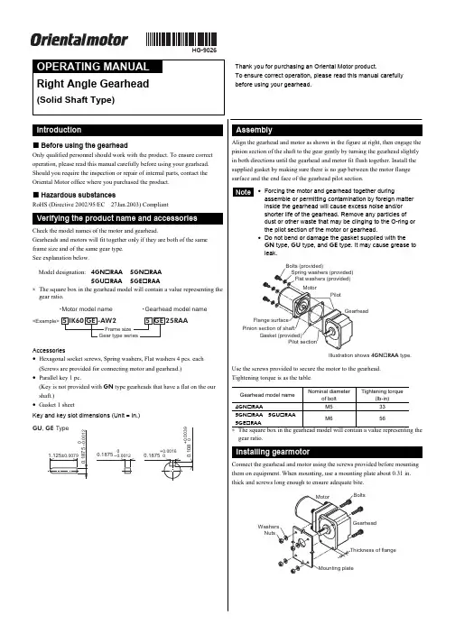
HG-9026Right Angle Gearhead(Solid Shaft Type)Thank you for purchasing an Oriental Motor product.To ensure correct operation, please read this manual carefully before using your gearhead.Before using the gearhead Only qualified personnel should work with the product. To ensure correct operation, please read this manual carefully before using your gearhead. Should you require the inspection or repair of internal parts, contact the Oriental Motor office where you purchased the product.Hazardous substances RoHS (Directive 2002/95/EC 27Jan.2003) CompliantCheck the model names of the motor and gearhead.Gearheads and motors will fit together only if they are both of the same frame size and of the same gear type. See explanation below.Model designation: 4GN RAA 5GN RAA5GU RAA 5GE RAA∗ The square box in the gearhead model will contain a value representing the gear ratio.<Example>5 IK60 GE -AW25 GE 25RAAFrame size Gear type series䊶Motor model name䊶Gearhead model nameAccessories• Hexagonal socket screws, Spring washers, Flat washers 4 pcs. each (Screws are provided for connecting motor and gearhead.)• Parallel key 1 pc.(Key is not provided with GN type gearheads that have a flat on the our shaft.)• Gasket 1 sheetKey and key slot dimensions (Unit = in.)GU , GE Type1.125±0.00790.1875+0.00160.18750-0.00120.18750-0.00120.108+0.0039Installation hole dimensions (Unit: in.)A±0.010A±0.0104×ØEB ±0.010C ±0.010ØDo r mo r eGearheadmodel nameScrew type Thicknessof flangeA B C ØDØE 4GN RAA No.10-24UNC 0.35 1.10 2.17 0.98 1.380.225GN RAA 1/4-20UNC 0.39 1.14 2.24 1.30 1.460.275GU RAA5GE RAA5/16-18UNC 0.47 1.18 2.64 1.30 1.380.33∗ The square box in the gearhead model will contain a value representing the gear ratio.The shaft of the gearhead has been machined to an outer diameter tolerance of h7 and is provided with a key slot for connecting the transmission parts. When connecting the transmission parts, ensure that the shaft and parts have a clearance fit, and secure with a screw to prevent the parts from wobbling. Use a screw hole (No.10-24UNC, effective depth 0.39 in.) provided at the tip of the output shaft of 5GU RAA and 5GE RAA as an auxiliary means for preventing the transfer mechanism from disengaging.< The example of output axistip screw hole use >Note • Do not use excessive force, or hammerthe transmission parts onto the gearmotor shaft as damage may occur. • Output shaft of 5GU120RAA to 5GU180RAA , 5GE120RAA to5GE180RAA cannot be turned by hand.For position alignment, turn on the motor.• Use your gearmotor under ambient temperature of +14 to +122 °F and85% humidity.• Do not use your gearmotor where it may be exposed direct sunlight waterand/or oil.• Do not use your gearmotor in locations subject to severe vibration or shock,a large amount of dust, inflammable gas and or corrosive gas.• On rare occasions, a small amount of grease may ooze out from thegearhead. If there is concern over possible environmental damage resulting from the leakage of grease, check for grease stains during regular inspections. Alternatively, install an oil pan or other device to prevent leakage from causing further damage. Oil leakage may lead to problems in the customer’s equipment or products.• If the ambient temperature is low, the motor may take a longer time to startor its speed may drop. This is caused, among others, by an increased friction torque of the oil seal used on the gearhead output shaft. As the motor continues to operate and the sliding part of the oil seal breaks in, the friction torque will drop and the motor will operate at the specified speed.• Direction of rotation of the gearhead output shaftThe motor and gearhead output shaft rotate in opposite directions.• Maximum permissible torqueSince the output torque of the gearhead increases proportionally with the reduction of speed, a high reduction ratio of the gearhead will result in anoutput torque that cannot be taken up by the physical construction of the gearhead. Use gearheads within the maximum permissible torque set for each speed reduction ratio. Also, be sure shaft rotation is not stopped by an external force or load obstruction. The resulting shock may damage the gearhead.• Permissible overhung load and permissible thrust load“Overhung load” refers to load placed on the output shaft of the gearhead in a direction perpendicular to the shaft as shown in the Figure below. The “Thrust load” is a load applied in the axial direction of the output shaft. Since the overhung load and thrust load have a great influence on the life of the bearings and strength of the shaft, be careful not to exceed the maximum values shown in the table at following.< Permissible overhung load and permissible thrust load >Permissibleoverhung load (lb)From the endof shaftGearhead model nameGear ratioMaximum permissibletorque(lb-in)0.39 in. 0.79 in.Permissible thrust load(lb)3 to 18 22 334GN RAA 25 to 18070 45 67 223 to 18 56 785GN RAA25 to 18088 67 101 453 to 9 90 11212.5 to 25101 135 5GU RAA 5GE RAA30 to 180177 112 15756∗ The square box in the gearhead model will contain a value representing thegear ratio.• Unauthorized reproduction or copying of all or part of this OperatingManual is prohibited.• Oriental Motor shall not be liable whatsoever for any patent-relatedproblem arising in connection with the use of any information, circuit, equipment or device described in the manual.• Characteristics, specifications and dimensions are subject to changewithout notice.• While we make every effort to offer accurate information in the manual,we welcome your input. Should you find unclear descriptions, errors or omissions, please contact the nearest office.•is a trademark of Oriental Motor Co., Ltd.© Copyright ORIENTAL MOTOR CO., LTD. 2006• Please contact your nearest Oriental Motor office for further information.ORIENTAL MOTOR U.S.A. CORP .Technical Support Line Tel:(800)468-3982Available from 7:30 AM to 5:00 PM, P .S.T.E-mail:*****************************ORIENTAL MOTOR CO., LTD.Headquarters Tokyo, JapanTel:(03)3835-0684 Fax:(03)3835-1890Printed on Recycled Paper。
东方马达BX系列1

BX6400S-□S
减速比 5~200 5~200 5~200 5~200 5~200 5~200 5~200 5~200 5~200
全套产品中包含下列各项单件。 电动机、减速机、驱动器、外部速度设定器(带信号线)、 驱动器用安装底座(附带螺丝)、安装用螺丝、平行键、使用说明书
◇联体型 · 中空轴扁平减速机
调
速
电 动
RoHS指令符合品
机 无刷电动机组合产品
BX系列
BX系列是高性能 · 高功能的无刷电动机组合产品。备 有从30W到大功率400W的各种产品。 在基本型的高性能之速度控制下,加上系统升级套件的 组合之后,即可使用转矩控制、定位控制等。
●相关信息● 技术资料➜ G-1页 安全规格➜ H-4页
BLE
无
刷
电 AC输入
动 机
AXU
●连续运行、原点返回 AC输入
可将定位数据6点中的2点连续运行使用。此外,也可以设定机械原 FBL 点返回、电气原点返回运行。
转矩限制(使用系统升级套件时)
●限制电动机的输出转矩 对应用途或使用状况,可控制电动机输出转矩。
作为制动器来获取张力
加压等 用途
张力
DC输入
电源电压 单相100-115V 单相、三相200-230V 单相100-115V 单相、三相200-230V 单相100-115V 单相、三相200-230V 单相100-115V 单相、三相200-230V 三相200-230V
品名 BX230A-A BX230C-A BX460A-A BX460C-A BX5120A-A BX5120C-A BX6200A-A BX6200C-A BX6400S-A
调 速 电 动 机
ORIENTALMOTOR日本东方马达及驱动选型RKSeries

ORIENTALMOTOR⽇本东⽅马达及驱动选型RKSeries RoHS-Compliant5-Phase Stepping Motor and Driver Package RK SeriesⅷStandard Type ⅷTH Geared TypeⅷPL Geared Type ⅷPN Geared TypeⅷHarmonic Geared Type2RoHS-Compliant5-Phase Stepping Motor and Driver PackageRK SeriesThe RK Series incorporates new functions and state-of-the-art technologies to achieve the ultimate use of a control motor. The seriesoffers various types including the standard type, electromagnetic brake type, IP65 rated motor type, and four geared types. Three frame sizes of 42 mm, 60 mm and 85 (90) mm are available. The wide range of motor variations and affordable prices make the RK Series a perfect solution for your various applications.ⅥFeaturesv bz Smooth Drive FunctionThe smooth drive function ensures low-vibration andlow-noise operation at low speeds by internally executing microstepping within the driver, working independently of the inputpulse frequency of your controller.V i b r a t i o n C o m p o n e n t V o l t a g e V p -p [V ]Speed [r/min]The smooth drive function of the RK Series improves the settling performance.S p e e d [r /m i n ]S p e e d [r /m in ]Conventional Model RK (Smooth Drive: ON)100 ms/div100 ms/divStep Angle: 0.72?/stepStep Angle: 0.72?/stepx Microstep Drive SystemThe motor's basic step angle is divided by a maximum of 1/250 without the use of a reduction mechanism or other mechanical elements. 16 resolution levels are available to set the desired resolution. This enables fine positioning and the further reduction of vibration and noise. A motion sequence of "low-speed transfer ? high-speed return" can easily be performed without the need for changing from a microstep pulse frequency to a full step pulse frequency. The RK Series can also be used in full-step operation.c 100-115 VAC, 200-230 VAC Power Source Variation The RK Series can be used with most common power supplies available around the world.They also comply with the international standards, ensuring safe operation.v Improved Angle AccuracyAngle accuracy may decrease during use of microstep drivers, due to the effect of current control. However, the drivers used in the RK Series are designed to ensure that the motor operates at maximum accuracy.A n g l e E rr o r [d e g ]0.0720.036-0.072-0.036Power Supply Voltage: 100-115 VAC b Improved ResponseThe RK Series, with its high starting frequency, shortens the machine cycle without affecting acceleration/deceleration rates. This produces a significant savings in time for an operation in which the same cycle is repeated thousands of times each day.Rise Time [ms]S p e e d [r /m i n ]3Features Line-upSystem ConfigurationProduct LineSpecifications and Characteristics DimensionsConnection and Operation List of Motor and Driver CombinationsAccessoriesBefore Using a Stepping MotorControllersⅷEnvironmentally Friendly Energy-Saving Mode In the energy-saving mode, the supply of current to the motor is stopped and the load is held only with the electromagnetic brake while the motor remains at a standstill. Stopping the supply of current to the motor extends the motor life by limiting the consumption of energy.(Available only with electromagnetic brake type)P o w e r C o n s u m p t i o n [k W ]Automatic Current-Cutback Modein Energy-Saving ModeComparison of Annual Power Consumption at ⅷSafe Operation in Major Countries around the World Compliance with Safety StandardsThe RK Series complies with the UL/CSA and ENstandards. (With the RK54Ⅺ type, only the driver conforms to the CSA standard.) The CE marking certifies compliance with the EMC Directive and Low-Voltage Directive.Additionally, the RK Series conforms to the EMC Directive only through its use of surge arrester. The RK Seriesdoesn't require an external ferrite core or filter in the motor line or power line.ⅷProtective Earth Terminal(Excluding motors with a frame size of 42 mm)The life of a motor is affected by its bearing. The RK Series achieves approx. twice the life of a conventional motor by adopting a modified bearing. (Available only with the standard type and standard electromagnetic-brake type with a frame size of 60 or 85 mm.)ⅷNew IP65 Rated Motor Conforming to the IP65 Standard for Ingress Protection against Dust and WaterTerminal-Block Connection DesignThe motor can be wired directly from its terminal block.No Motor/Driver RelaySince the motor cable can be connected directly with the driver terminals, there is no need for wire connection orsoldering on a relay terminal block.DriverRoHS-CompliantThe RK Series conforms to the RoHS Directive thatprohibits the use of six chemical substances including lead and cadmium.ⅥWide VarietyThe RK Series offers a range of motor frame sizes depending on the motor type and power supply voltage specification, as shown below.□ⅷStandard Type/Standard Type IP65 Rated MotorEasy-to-use standard types offer balanced performance. The IP65 rated motor conforms to the IP65 standard for ingress protectionagainst dust and water.ⅷStandard Type with Electromagnetic BrakeA motor combines with power off activated type electromagnetic brake.TH Geared Type (Low backlash)A low-cost geared motor offers low backlash.ⅷPL Geared Type (Low backlash)A geared motor offers low backlash, high strength and wide gear ratios.ⅷPNGeared Type (Non-backlash)A high-accuracy geared motor achieves a backlash of 3 arc minutes or less. It also provides high strength and wide gear ratios.Harmonic Geared Type(Non-backlash)A high-accuracy, backlash-free geared motor adopts a newly developed harmonic gear. It ensures high strength in a compact body.45FeaturesLine-upSystem ConfigurationProduct LineSpecifications and CharacteristicsDimensionsConnection and Operation List of Motor and Driver Combinations Accessories Before Using a Stepping Motor ControllersTH (Parallel Shaft)PL (Harmonic Drive)ⅥSystem ConfigurationAn example of a system configuration with the SG8030 Series controller.Mounting Brackets (Accessories)Connector-Terminal BlockDriverⅷThe system configuration shown above is an example. Other combinations are available.67Features Line-upSystem ConfigurationProduct LineSpecifications and CharacteristicsDimensionsConnection and Operation List of Motor and Driver CombinationsAccessoriesBefore Using a Stepping Motor ControllersⅥProduct Number Codeqw e r t y u io !0RK 5 6 6 B A E - N 5Series RK :RK Series 5: 5-PhaseMotor Frame Size 4: 42 mm6: 60 mm 9: 85 mm (90 mm sq. for Geared Type)Motor Case LengthMotor Shaft Type A : Single Shaft B : Double ShaftElectromagnetic Brake Blank : Without Electromagnetic Brake M : With Electromagnetic Brake Power Supply Voltage A : Single-Phase 100-115 VAC C : Single-Phase 200-230 VAC Motor Classi? c ation TypeBlank : Standard Type T :TH Geared TypeP :PL Geared Type N :PN Geared Type H : Harmonic Geared TypeGear RatioⅥProduct Line89 Features Line-up System ConfigurationProduct LineSpecifications and CharacteristicsDimensionsConnection and Operation List of Motor and Driver CombinationsAccessoriesBefore Using a Stepping Motor ControllersStandard Type Motor Frame Size 42 mmⅥSpecificationsⅷWith the RK54Ⅺ type, only the driver conforms to the CSA standard.RK543AA RK544AA RK545AA RK543BA RK544BA RK545BAHow to Read Specifications Table ?See the following descriptions.Sixteen resolutions are available, where n=1, 2, 2.5, 4, 5, 8, 10, 20, 25, 40, 50, 80, 100, 125, 200 and 250.ⅥSpeed – Torque Characteristics fs: Maximum Starting FrequencyRK543AA/RK543BAPulse Speed [kHz](0)(300)(200)(100)(Resolution 10)Speed [r/min]T o r q u e [N ?m ]C u r r e n t [A ]132Current: 0.75 A/Phase Step Angle: 0.72?/step 2RK544AA/RK544BAPulse Speed [kHz]0(0)30(300)20(200)10(100)Resolution 1(Resolution 10)Speed [r/min]T o r q u e [N ?m ]C u r r e n t [A ]132Current: 0.75 A/Phase Step Angle: 0.72?/step 2RK545AA/RK545BAPulse Speed [kHz]0(0)30(300)20(200)10(100)Resolution 1(Resolution 10)Speed [r/min]T o r q u e [N ?m ]C u r r e n t [A ]132Current: 0.75 A/Phase Step Angle: 0.72?/step 2ⅷThe pulse input circuit responds to approximately 200 kHz with a pulse duty of 50%.Notes:ⅷPay attention to heat dissipation from motor as there will be a considerable amount of heat under certain conditions.Be sure to keep the temperature of the motor case under 100?C.(Under 75?C is required to comply with UL or CSA standards.)ⅷWhen using the motor with the dedicated driver, the driver’s automatic current cutback function at motor standstill reduces maximum holding torque by approximately 50%.ⅥHow to Read Specifications TablePlease read the following information before examining the specifications on pages 9 to 23.10Standard Type Motor Frame Size 60 mm, 85 mmHow to Read Specifications Table ?Page 9Sixteen resolutions are available, where n=1, 2, 2.5, 4, 5, 8, 10, 20, 25, 40, 50, 80, 100, 125, 200 and 250.ⅥSpeed – Torque Characteristics fs: Maximum Starting FrequencyRK564ⅪAE RK564ⅪCEPulse Speed [kHz]0(0)10(100)20(200)30(300) Speed [r/min]T o r q u e [N ?m ]Resolution 1(Resolution 10)C u r r e n t [A ]462Current: 1.4 A/Phase Step Angle: 0.72?/step 2RK566ⅪAE RK566ⅪCEPulse Speed [kHz](0)10(100)20(200)30(300) Speed [r/min]T o r q u e [N ?m ]Resolution 1(Resolution 10)C u r r e n t [A ]48Current: 1.4 A/Phase Step Angle: 0.72?/step 2RK569ⅪAE RK569ⅪCEPulse Speed [kHz]0(0)10(100)20(200)30(300) Speed [r/min]T o r q u e [N ?m ]Resolution 1(Resolution 10)C u r r e n t [A ]48Current: 1.4 A/Phase Step Angle: 0.72?/step 2ⅷEnter A (Single shaft) or B (Double shaft) in the box (Ⅺ) within the model name.ⅷThe pulse input circuit responds to approximately 200 kHz with a pulse duty of 50%.Notes:ⅷPay attention to heat dissipation from motor as there will be a considerable amount of heat under certain conditions.Be sure to keep the temperature of the motor case under 100?C.(Under 75?C is required to comply with UL or CSA standards.)ⅷWhen using the motor with the dedicated driver, the driver’s automatic current cutback function at motor standstill reduces maximum holding torque by approximately 50%.RK596ⅪAE RK596ⅪCEPulse Speed [kHz](0)(100)(200) Speed [r/min](Resolution 10)T o r q u e [N ?m ]C u r r e n t [A ]510Current: 1.4 A/Phase Step Angle: 0.72?/step 2 RK599ⅪAE RK599ⅪCEPulse Speed [kHz]Speed [r/min](Resolution 10)(0)(50)(100)T o r q u e [N ?m ]C u r r e n t [A ]48Current: 1.4 A/Phase Step Angle: 0.72?/step 2 RK5913ⅪAERK5913ⅪCEPulse Speed [kHz](0)(50)(100) Speed [r/min](Resolution 10)T o r q u e [N ?m ]C u r r e n t [A ]48Current: 1.4 A/Phase Step Angle: 0.72?/step 2 11FeaturesLine-upSystem ConfigurationProduct LineSpecifications and Characteristics DimensionsConnection and Operation List of Motor and Driver CombinationsAccessoriesBefore Using a Stepping Motor ControllersStandard Type IP65 Rated Motor Motor Frame Size 60 mm, 85 mmⅥSpecificationsHow to Read Specifications Table ?Page 91Sixteen resolutions are available, where n=1, 2, 2.5, 4, 5, 8, 10, 20, 25, 40, 50, 80, 100, 125, 200 and 250.2Excluding the gap between the shaft and the flangeⅥSpeed – Torque Characteristics fs: Maximum Starting FrequencyRK564AAT/RK564ACTPulse Speed [kHz]0(0)10(100)20(200)30(300)Speed [r/min]T o r q u e [N ?m ]Resolution 1(Resolution 10)C u r r e n t [A ]462Current: 1.4 A/Phase Step Angle: 0.72?/step 2RK566AAT/RK566ACTPulse Speed [kHz]0(0)10(100)20(200)30(300) Speed [r/min]T o r q u e [N ?m ]Resolution 1(Resolution 10)C u r r e n t [A ]48Current: 1.4 A/Phase Step Angle: 0.72?/step 2RK569AAT/RK569ACTPulse Speed [kHz]0(0)10(100)20(200)30(300) Speed [r/min]T o r q u e [N ?m ]Resolution 1(Resolution 10)C u r r e n t [A ]48Current: 1.4 A/Phase Step Angle: 0.72?/step 2ⅷThe pulse input circuit responds to approximately 200 kHz with a pulse duty of 50%.Notes:ⅷPay attention to heat dissipation from motor as there will be a considerable amount of heat under certain conditions.Be sure to keep the temperature of the motor case under 100?C.(Under 75?C is required to comply with UL or CSA standards.)ⅷWhen using the motor with the dedicated driver, the driver’s automatic current cutback function at motor standstill reduces maximum holding torque by approximately 50%.RK596AAT/RK596ACTPulse Speed [kHz]0(0)10(100)20(200) Speed [r/min]Resolution 1(Resolution 10)T o r q u e [N ?m ]C u r r e n t [A ]510Current: 1.4 A/Phase Step Angle: 0.72?/step2RK599AAT/RK599ACTPulse Speed [kHz]Speed [r/min]Resolution 1(Resolution 10)0(0)5(50)10(100)T o r q u e [N ?m ]C u r r e n t [A ]48Current: 1.4 A/Phase Step Angle: 0.72?/step 2RK5913AAT/RK5913ACTPulse Speed [kHz]0(0)5(50)10(100) Speed [r/min]Resolution 1(Resolution 10)T o r q u e [N ?m ]C u r r e n t [A ]48Current: 1.4 A/Phase Step Angle: 0.72?/step 212Standard Type with Electromagnetic Brake Motor Frame Size 42 mm ⅥSpecificationsⅷWith the RK54Ⅺtype, only the driver conforms to the CSA standard.How to Read Specifications Table ?Page 9Sixteen resolutions are available, where n=1, 2, 2.5, 4, 5, 8, 10, 20, 25, 40, 50, 80, 100, 125, 200 and 250.ⅥSpeed – Torque Characteristics fs: Maximum Starting FrequencyRK543AMAPulse Speed [kHz]0(0)30(300)20(200)10(100)Resolution 1(Resolution 10)Speed [r/min]T o r q u e [N ?m ]C u r r e n t [A ]132Current: 0.75 A/Phase Step Angle: 0.72?/step 2RK544AMAPulse Speed [kHz]0(0)30(300)20(200)10(100)Resolution 1(Resolution 10)Speed [r/min]T o r q u e [N ?m ]C u r r e n t [A ]132Current: 0.75 A/Phase Step Angle: 0.72?/step 2RK545AMAPulse Speed [kHz]0(0)30(300)20(200)10(100)Resolution 1(Resolution 10)Speed [r/min]T o r q u e [N ?m ]C u r r e n t [A ]132Current: 0.75 A/Phase Step Angle: 0.72?/step 2ⅷThe pulse input circuit responds to approximately 200 kHz with a pulse duty of 50%.Notes:ⅷPay attention to heat dissipation from motor as there will be a considerable amount of heat under certain conditions.Be sure to keep the temperature of the motor case under 100?C.(Under 75?C is required to comply with UL or CSA standards.)ⅷWhen using the motor with the dedicated driver, the driver’s automatic current cutback function at motor standstill reduces maximum holding torque by approximately 50%.13FeaturesLine-upSystem Configuration Product LineSpecifications and CharacteristicsDimensionsConnection and Operation List of Motor and Driver CombinationsAccessoriesBefore Using a Stepping Motor ControllersStandard Type with Electromagnetic Brake Motor Frame Size 60 mm, 85 mmⅥSpecificationsHow to Read Specifications Table ?Page 9Sixteen resolutions are available, where n=1, 2, 2.5, 4, 5, 8, 10, 20, 25, 40, 50, 80, 100, 125, 200 and 250.ⅥSpeed – Torque Characteristics fs: Maximum Starting FrequencyRK564AMAE RK564AMCEPulse Speed [kHz]0(0)10(100)20(200)30(300)Speed [r/min]T o r q u e [N ?m ]Resolution 1(Resolution 10)C u r r e n t [A ]462Current: 1.4 A/Phase Step Angle: 0.72?/step 2RK566AMAE RK566AMCEPulse Speed [kHz]0(0)10(100)20(200)30(300) Speed [r/min]T o r q u e [N ?m ]Resolution 1(Resolution 10)C u r r e n t [A ]48Current: 1.4 A/Phase Step Angle: 0.72?/step 2RK569AMAE RK569AMCEPulse Speed [kHz]0(0)10(100)20(200)30(300) Speed [r/min]T o r q u e [N ?m ]Resolution 1(Resolution 10)C u r r e n t [A ]48Current: 1.4 A/Phase Step Angle: 0.72?/step 2ⅷThe pulse input circuit responds to approximately 200 kHz with a pulse duty of 50%.Notes:ⅷPay attention to heat dissipation from motor as there will be a considerable amount of heat under certain conditions.Be sure to keep the temperature of the motor case under 100?C.(Under 75?C is required to comply with UL or CSA standards.)ⅷWhen using the motor with the dedicated driver, the driver’s automatic current cutback function at motor standstill reduces maximum holding torque by approximately 50%.RK596AMAE RK596AMCEPulse Speed [kHz]0(0)10(100)20(200) Speed [r/min]Resolution 1(Resolution 10)T o r q u e [N ?m ]C u r r e n t [A ]510Current: 1.4A/Phase Step Angle: 0.72? step 2RK599AMAE RK599AMCEPulse Speed [kHz]0(0)Speed [r/min]Resolution 1(Resolution 10)5(50)10(100)T o r q u e [N ?m ]C u r r e n t [A ]48Current: 1.4 A/Phase Step Angle: 0.72?/step 2 RK5913AMAE RK5913AMCEPulse Speed [kHz]0(0)5(50)10(100) Speed [r/min]Resolution 1(Resolution 10)T o r q u e [N ?m ]C u r r e n t [A ]48Current: 1.4 A/Phase Step Angle: 0.72?/step 2 14TH Geared Type Motor Frame Size 42 mmⅥSpecificationsⅷWith the RK54Ⅺtype, only the driver conforms to the CSA standard.How to Read Specifications Table ?Page 9Sixteen resolutions are available, where n=1, 2, 2.5, 4, 5, 8, 10, 20, 25, 40, 50, 80, 100, 125, 200 and 250.Note:ⅷDirection of rotation of the motor and that of the gear output shaft are the same for models with gear ratios of 1:3.6, 1:7.2 and 1:10. It is opposite for 1:20 and 1:30 gear ratio models.ⅥSpeed – Torque Characteristics fs: Maximum Starting FrequencyRK543AA-T3.6/RK543BA-T3.6Pulse Speed [kHz]0(0)15(150)10(100)5(50)Resolution 1(Resolution 10)Speed [r/min]T o r q u e [N ?m ]C u r r e n t [A ]12Current: 0.75 A/Phase Step Angle: 0.2?/step 2RK543AA-T7.2/RK543BA-T7.2Pulse Speed [kHz]0(0)15(150)10(100)5(50)Resolution 1(Resolution 10)Speed [r/min]T o r q u e [N ?m ]C u r r e n t [A ]12Current: 0.75 A/Phase Step Angle: 0.1?/step 2RK543AA-T10/RK543BA-T10Pulse Speed [kHz]Resolution 1(Resolution 10)Speed [r/min]0(0)5(50)10(100)15(150)T o r q u e [N ?m ]C u r r e n t [A ]12Current: 0.75 A/Phase Step Angle: 0.072?/step 2ⅷThe pulse input circuit responds to approximately 200 kHz with a pulse duty of 50%.Notes:ⅷPay attention to heat dissipation from motor as there will be a considerable amount of heat under certain conditions.Be sure to keep the temperature of the motor case under 100?C.(Under 75?C is required to comply with UL or CSA standards.)ⅷWhen using the motor with the dedicated driver, the driver’s automatic current cutback function at motor standstill reduces maximum holding torque by approximately 50%.RK543AA-T20/RK543BA-T20Pulse Speed [kHz]Resolution 1(Resolution 10)Speed [r/min]0(0)5(50)10(100)15(150)T o r q u e [N ?m ]C u r r e n t [A ]12Current: 0.75 A/Phase Step Angle: 0.036?/step 2RK543AA-T30/RK543BA-T30T o rq u e [N ?m ]C u r r e n t [A ]12Pulse Speed [kHz]Resolution 1(Resolution 10)Speed [r/min]0(0)5(50)10(100)15(150)Current: 0.75 A/Phase Step Angle: 0.024?/step 215FeaturesLine-upSystemConfiguration Product LineSpecifications and CharacteristicsDimensionsConnection and Operation List of Motor and Driver Combinations AccessoriesBefore Using a Stepping MotorControllersTH Geared Type Motor Frame Size 60 mmⅥSpecificationsHow to Read Specifications Table ?Page 9Sixteen resolutions are available, where n=1, 2, 2.5, 4, 5, 8, 10, 20, 25, 40, 50, 80, 100, 125, 200 and 250.Note:ⅷDirection of rotation of the motor and that of the gear output shaft are the same for models with gear ratios of 1:3.6, 1:7.2 and 1:10. It is opposite for 1:20 and 1:30 gear ratio models.ⅥSpeed – Torque Characteristics fs: Maximum Starting FrequencyRK564ⅪAE-T3.6 RK564ⅪCE-T3.6Pulse Speed [kHz]0(0)15(150)10(100)5(50)Resolution 1(Resolution 10)Speed [r/min]T o r q u e [N ?m ]C u r r e n t [A ]24Current: 1.4 A/Phase Step Angle: 0.2?/step 2RK564ⅪAE-T7.2 RK564ⅪCE-T7.2Pulse Speed [kHz]0(0)15(150)10(100)Resolution 1(Resolution 10)Speed [r/min]T o r q u e [N ?m ]C u r r e n t [A ]48Current: 1.4 A/Phase Step Angle: 0.1?/step 2RK564ⅪAE-T10 RK564ⅪCE-T10Pulse Speed [kHz]Resolution 1(Resolution 10)Speed [r/min]0(0)5(50)10(100)15(150)T o r q u e [N ?m ]C u r r e n t [A ]24Current: 1.4 A/Phase Step Angle: 0.072?/step 2ⅷEnter A (Single shaft) or B (Double shaft) in the box (Ⅺ) within the model name.ⅷThe pulse input circuit responds to approximately 200 kHz with a pulse duty of 50%.Notes:ⅷPay attention to heat dissipation from motor as there will be a considerable amount of heat under certain conditions.Be sure to keep the temperature of the motor case under 100?C.(Under 75?C is required to comply with UL or CSA standards.)ⅷWhen using the motor with the dedicated driver, the driver’s automatic current cutback function at motor standstill reduces maximum holding torque by approximately 50%.RK564ⅪAE-T20 RK564ⅪCE-T20Pulse Speed [kHz]Resolution 1(Resolution 10)Speed [r/min]0(0)5(50)15(150)T o r q u e [N ?m ]C u r r e n t [A ]24Current: 1.4 A/Phase Step Angle: 0.036?/step 2RK564ⅪAE-T30 RK564ⅪCE-T30Pulse Speed [kHz]Resolution 1(Resolution 10)Speed [r/min]0(0)5(50)10(100)15(150)T o r q u e [N ?m ]C u r r e n t [A ]24Current: 1.4 A/Phase Step Angle: 0.024?/step 216TH Geared Type Motor Frame Size 90 mmⅥSpecificationsHow to Read Specifications Table ?Page 9Sixteen resolutions are available, where n=1, 2, 2.5, 4, 5, 8, 10, 20, 25, 40, 50, 80, 100, 125, 200 and 250.Note:ⅷDirection of rotation of the motor and that of the gear output shaft are the same for models with gear ratios of 1:3.6, 1:7.2 and 1:10. It is opposite for 1:20 and 1:30 gear ratio models.ⅥSpeed – Torque Characteristics fs: Maximum Starting FrequencyRK596ⅪAE-T3.6 RK596ⅪCE-T3.6Pulse Speed [kHz]0(0)15(150)10(100)5(50)Resolution 1(Resolution 10)Speed [r/min]T o r q u e [N ?m ]C u r r e n t [A ]2.55Current: 1.4 A/Phase Step Angle: 0.2?/step 2 RK596ⅪAE-T7.2 RK596ⅪCE-T7.2Pulse Speed [kHz]0(0)15(150)10(100)5(50)Resolution 1(Resolution 10)Speed [r/min]T o r q u e [N ?m ]C u r r e n t [A ]2.55Current: 1.4 A/Phase Step Angle: 0.1?/step 2 RK596ⅪAE-T10 RK596ⅪCE-T10Pulse Speed [kHz]Resolution 1(Resolution 10)Speed [r/min]0(0)5(50)10(100)15(150)T o r q u e [N ?m ]C u r r e n t [A ]264Current: 1.4 A/Phase Step Angle: 0.072?/step 2ⅷEnter A (Single shaft) or B (Double shaft) in the box (Ⅺ) within the model name.ⅷThe pulse input circuit responds to approximately 200 kHz with a pulse duty of 50%.Notes:ⅷPay attention to heat dissipation from motor as there will be a considerable amount of heat under certain conditions.Be sure to keep the temperature of the motor case under 100?C.(Under 75?C is required to comply with UL or CSA standards.)ⅷWhen using the motor with the dedicated driver, the driver’s automatic current cutback function at motor standstill reduces maximum holding torque by approximately 50%.RK596ⅪAE-T20 RK596ⅪCE-T20C u r r e n t [A ]Pulse Speed [kHz](Resolution 10)(0)(50)(100)(150)Current: 1.4 A/Phase Step Angle: 0.036?/step 2RK596ⅪAE-T30 RK596ⅪCE-T30C u r r e n t [A ]Pulse Speed [kHz](Resolution 10)(0)(50)(150)Current: 1.4 A/Phase Step Angle: 0.024?/step 217FeaturesLine-upSystem ConfigurationProduct LineSpecifications and CharacteristicsDimensionsConnection and Operation List of Motor and Driver CombinationsAccessoriesBefore Using a Stepping Motor ControllersPL Geared Type Motor Frame Size 42 mmⅥSpecificationsⅷWith the RK54Ⅺ type, only the driver conforms to the CSA standard.How to Read Specifications Table ?Page 9Sixteen resolutions are available, where n=1, 2, 2.5, 4, 5, 8, 10, 20, 25, 40, 50, 80, 100, 125, 200 and 250.Note:ⅷDirection of rotation of the motor and that of the gear output shaft are the same.ⅥSpeed – Torque Characteristics fs: Maximum Starting FrequencyRK545AA-P5 RK545BA-P5Pulse Speed [kHz]Resolution 1(Resolution 10)Speed [r/min]0(0)5(50)15(150)T o r q u e [N ?m ]C u r r e n t [A ]12Current: 0.75 A/Phase Step Angle: 0.144?/step 2RK545AA-P7.2RK545BA-P7.2Pulse Speed [kHz]0(0)15(150)10(100)5(50)Resolution 1(Resolution 10)Speed [r/min]T o r q u e [N ?m ]C u r r e n t [A ]12Current: 0.75 A/Phase Step Angle: 0.1?/step 2RK545AA-P10RK545BA-P10Pulse Speed [kHz]Resolution 1(Resolution 10)Speed [r/min]0(0)5(50)10(100)15(150)T o r q u e [N ?m ]C u r r e n t [A ]12Current: 0.75 A/Phase Step Angle: 0.072?/step 2ⅷThe pulse input circuit responds to approximately 200 kHz with a pulse duty of 50%.Notes:ⅷPay attention to heat dissipation from motor as there will be a considerable amount of heat under certain conditions.Besure to keep the temperature of the motor case under 100?C.(Under 75?C is required to comply with UL or CSA standards.)ⅷWhen using the motor with the dedicated driver, the driver’s automatic current cutback function at motor standstill reduces maximum holding torque by approximately 50%.RK543AA-P25 RK543BA-P25Pulse Speed [kHz]Resolution 1(Resolution 10)Speed [r/min](0)(50)(100)(150)T o r q u e [N ?m ]C u r r e n t [A ]12Current: 0.75 A/Phase Step Angle: 0.0288?/step2RK543AA-P36 RK543BA-P36Pulse Speed [kHz]0(0)15(150)10(100)5(50)Resolution 1(Resolution 10)Speed [r/min]T o r q u e [N ?m ]C u r r e n t [A ]21Current: 0.75 A/Phase Step Angle: 0.02?/step2RK543AA-P50 RK543BA-P50Pulse Speed [kHz]0(0)15(150)10(100)5(50)Resolution 1(Resolution 10)Speed [r/min]T o r q u e [N ?m ]C u r r e n t [A ]21Current: 0.75 A/Phase Step Angle: 0.0144?/step 218PL Geared Type Motor Frame Size 60 mmⅥSpecificationsHow to Read Specifications Table ?Page 9Sixteen resolutions are available, where n=1, 2, 2.5, 4, 5, 8, 10, 20, 25, 40, 50, 80, 100, 125, 200 and 250.Note:ⅷDirection of rotation of the motor and that of the gear output shaft are the same.ⅥSpeed – Torque Characteristics fs: Maximum Starting FrequencyRK566ⅪAE-P5 RK566ⅪCE-P5Pulse Speed [kHz]Resolution 1(Resolution 10)Speed [r/min]0(0)5(50)10(100)15(150)T o r q u e [N ?m ]C u r r e n t [A ]48Current: 1.4 A/Phase Step Angle: 0.144?/step 2RK566ⅪAE-P7.2 RK566ⅪCE-P7.2Pulse Speed [kHz](0)(150)(100)(50)Resolution 1(Resolution 10)Speed [r/min]T o r q u e [N ?m ]C u r r e n t [A ]48Current: 1.4 A/Phase Step Angle: 0.1?/step 2RK566ⅪAE-P10 RK566ⅪCE-P10Pulse Speed [kHz]Resolution 1(Resolution 10)Speed [r/min](0)(50)(100)(150)T o r q u e [N ?m ]C u r r e n t [A ]48Current: 1.4 A/Phase Step Angle: 0.072?/step 2ⅷEnter A (Single shaft) or B (Double shaft) in the box (Ⅺ) within the model name.ⅷThe pulse input circuit responds to approximately 200 kHz with a pulse duty of 50%.Notes:ⅷPay attention to heat dissipation from motor as there will be a considerable amount of heat under certain conditions.Be sure to keep the temperature of the motor case under 100?C.(Under 75?C is required to comply with UL or CSA standards.)。
东方马达 CMK系列
部分的转轴。
60
21
Q 驱动器 11 驱动器部 品名:CMD2109P、CMD2112P、CMD2120P M 质量:0.05kg B441
13 3.5
12
17.4 20.55
12
17.55 2R1.75
7.4 59
2R1.75 3.5 33
P附件
连接器插头 51103-0200(MOLEX) 51103-1200(MOLEX) 51103-0600(MOLEX) 接点 50351-8100(MOLEX)
P 品名的 中为表示减速比的数值。
安装用螺丝 M4 P0. 长度 15mm…4 个 6.350.012 5.80.15
0
P附件
161 150.25
60
控制器
24
700.5
M56.4
4M4 深度 8 电动机导线 6 根 300mm UL Style 3265, AWG22
P 此外形图为双轴产品。单轴产品则无
7.50.15
12
0
P适用接器
18.5
6
1
29 44.5 孔
连接器插头:5106-0600(MOLEX) 接点:5021-9101(MOLEX) 压接工具:5189-5000(MOLEX) 5190-5000(MOLEX)
P 此外形图为双轴产品。单轴产品则无
部分的转轴。
19
品名 CMK243AP CMK243MAP CMK243BP CMK243MBP CMK244AP CMK244MAP CMK244BP CMK244MBP CMK245AP CMK245MAP CMK245BP CMK245MBP
✽
4.50.15 0 50.012(h7)
东方马达pk5_cp
进
电 动
RoHS指令符合品
机 5相步进电动机
PK系列
5相PK系列为每转500分割(0.72˚/step )的高转矩 · 低 振动型步进电动机。为了适应所有的驱动方式,导线规 格设计为10条导线。驱动本系列时需另购驱动器。
●相关信息● 技术资料➜ G-1页
■品名的阅读方法
PK 5 6 6 H - B
C-130 C-170
− RK596□ ■E
− RK599□ ■E
− −
− C-130
− C-130
− −
外形图 编号
■转速―转矩特性 转速―转矩特性的阅读方法 ➜ C-10页
PK564-A/PK564-B
恒流驱动器 电源电压:DC24V 设定电流:0.75A/相(4相励磁时) 附带制振器D6CL-8.0F:JL=140×10-7kg·m2 0.6
规格表的阅读方法 ➜ C-10页 ● 上表电动机的转速―转矩特性请参考相当的组合产品的特性。若无相当的组合品名,请参考以下特性。 ● 品名的 □ 中为表示轴形的 A 或 B。
品名的■中为表示电源输入的A或C。
质量 kg 0.21 0.27 0.35 0.6
0.8
1.3 1.7 2.8 3.8
相当的组合品名及转速― 转矩特性 刊载页
PK569H-A/PK569H-B
恒流驱动器 电源电压:DC24V 设定电流:2.8A/相(4相励磁时) 附带制振器D6CL-8.0F:JL=140×10-7kg·m2 2.5
整步0.72˚/step 2.0
转矩[N·m]
1.5 最大同步转矩
1.0
0.5
00
fs 500
1000
转速[r/min]
伺服电动机 - 首页东方马达(ORIENTAL MOTOR)中国官 …
12.7 18
12.7
屏蔽
300+300
13.9
1000+080
● 适用压接端子 · 端子螺丝尺寸 :M3 · 紧固转矩 :1.2N·m · 最小适用导线 :AWG22( 0.3mm2 )
请注意 ● 不能使用圆形端子。
12.7 13.9 3.2mm以上
5.8 mm以上 4.2 mm以下
CAD、选型 官方网站 使用说明书
带圆形绝缘膜被的压接端子(1.25-4)
52316-2019(Molex)
52316-2019(Molex) 54331-1201(Molex)
54331-1201(Molex) 300+030
ϕ7.5 43.46 33.3
ϕ6.4 6.2 mm以下
33.3
43.46
12.7 18
屏蔽
300+300 1000+080
耦合器外罩
圆形端子:FV1.25-4(JST)
◇ 电磁制动用电缆线
电动机侧
驱动器侧
5559-02P-210(Molex) 棒状端子 :AI0.5-8WH (PHOENIX CONTACT)
ϕ4.1(可动电缆线为ϕ6)
耦合器外罩
CAD、选型 官方网站 使用说明书
带圆形绝缘膜被的压接端子(1.25-4)
52316-3619(Molex)
52316-3619(Molex)
54331-1361(Molex)
54331-1361(Molex)
300
+30 0
端子台端子编号
11 12 13 14 15 16 17 18 19 20 1 2 3 4 5 6 7 8 9 10
BMU东方马达说明书
设置
• 电动机、驱动器周围请勿堆放妨碍通风的障碍物,否则有可能造成装置破损。 • 搬运时请勿手持电动机(减速机)输出轴和电缆线,否则有可能致伤。 • 请勿徒手碰触电动机输出轴(键槽、切齿部),否则有可能致伤。 • 电动机(齿轮轴)与减速机组装时,请注意勿将手指等夹在电动机与减速机之间,否则有可能致伤。 • 请将电动机(减速机)、驱动器牢固固定在安装板上,否则有可能因落下致伤或造成装置破损。 • 电动机(减速机)的旋转部(输出轴)上请安装外罩,否则有可能致伤。 • 将电动机(减速机)设置在装置上时,注意勿将手指等夹在装置与电动机或装置与减速机之间,否则有可能
6 连接....................................................14
6.1 电源的连接 ............................................ 14 6.2 电动机的连接......................................... 14 6.3 接地 ....................................................... 15 6.4 输入/输出信号的连接 .......................... 15 6.5 连接例 ................................................... 17
联体型平行轴减速机的设置 ...................... 10 减速机的拆卸・安装................................... 11 圆轴型的设置............................................ 11 负载的安装 ............................................... 12 容许径向负载与容许轴向负载 .................. 12 5.3 驱动器的设置......................................... 13