S型称重传感器stc说明书
STC(Straight Tip Cartridge )操作指南说明书

TABLE OF CONTENTS1.Safety Precautions2.Confirmation and Precautions Before Operation3.External Dimension Diagram of Each Part5.Adapter Block6.Sensor Pack(Option)7.Maintenance7-1. Cap Tip Loading Procedure7-2. Cartridge Disassembly Procedure7-3. Cartridge Mounting Procedure8.Example of Cap Tip Insertion Operation9. Robot Teaching10. Problems and Solutions11. Replacement List12. Order ModelContact 2 424 37 32 18 20 22 5131428 33 3 35■Please read "Safety Precautions" carefully before using, and use our product correctly.This product is a device where a cap tip is inserted.Please do not use it for any purpose other than its intended use. Our company does not bear any responsibility with respect to failures, repairs, accidents, or other problems when using our product outside of its intended use. Please understand this point.■Regarding signs"Safety Precautions" provided in this instruction manual to prevent risks and obstacles for you and other people in advance is divided into "Warning" and "Caution" for information. Since both are important contents concerning safety, please be sure to observe them.It indicates contents informing possibilities of death or serious injury in case of incorrect handling.It indicates contents informing possibilities of injury due to handling error or occurrence of material damages.■Examples of SignsTypes of contents to be observed are explained by classification with graphical symbols. (Below are examples of graphical symbols)This symbol indicates operations that should not be done.This symbol indicates operation that should be done.Handling precautionsNever disassemble or modify. ● It may cause injury or operationfailure.Do not insert fingers or hands during operation. ● Injury may occur due to getting suckedin or caught.Please do not sprinkle a large amount of water.● Rush may occur to cause operationfailure.Please do not use chlorine-based or acidic cleaner for cleaning the main body. ● Toxic gas generated from the cleanermay harm your health.Contamination on the main body must be removed regularly.● If contamination is accumulated,it may cause operation failure.When using alcohol, paint thinner, or volatile lubricant for cleaning the main body, please wipe it off well.● When spatter is accumulated on volatilelubricant, it may cause ignition.2.1)This product is used when mounting cap tip with robot gun.2)Upper and lower cartridges can be distinguished by color.Generally, "yellow is for the upper side" and "blue for the lower side".3)Please use unused cap tip for loading.If scratches or contaminations are prominent on used caps or outer tapers, operation failure may occur.※The maximum number of loading are for φ16 → 12pcs /for φ13 → 14pcs /for φ19, 20 → 10pcs.4)Installation place must be where spatter and cooling water do not directly fall down as much as possible.5)Remove dust or foreign substances from the cartridge when they are caught in the cartridge. When cleaning inside, please disassemble. (Please refer to 7-2. Cartridge Disassembly Procedure)6)Please make sure that the cartridge is securely fastened before use. Also, make sure that the cartridge model being used is correct.7)Please make sure that the cap tip is loaded in the cartridge, or the cap tip is used correctly.8)During operation, set the applied gun pressure within 120kgf-150kgf . ※If 150kgf or more is used, the product may be damaged. ※If 120kgf or less is used, the tip may not be set on a shank.9)Do not drop this product.※This product could be broken if it is dropped or hit since it is resin. For Upper Side STC-****U For Lower Side STC-****LWeight about 0.5kg⑤①②③ ④ ⑥⑦⑧⑨⑩⑪⑫⑬①②⑤⑥⑦⑧⑨⑩⑪⑫ ⑬⑤①②③ ④ ⑥⑦⑧⑨⑩⑪⑫⑬①②⑤⑥⑦⑧⑨⑩⑪⑫ ⑬⑤①②③ ④ ⑥⑦⑧⑨⑩⑪⑫④⑩②⑤⑥⑦⑧⑫⑨⑪①⑤①②③ ④ ⑥⑦⑧⑨⑩⑪⑫④⑩②⑤⑥⑦⑧⑫⑨⑪①2)STC-ADB-**L-PP-SET for Lower SideAssemble the proximity sensor in the position below.(Important) Please be careful not to make a mistake because the assembly position is fixed. ** indicate cap tip outer diameters of the usage cap tip.①②③④④④<Wire Reference>1) Limit Switch Wire Color (D4CC-4060)Terminal No.WireColorTerminal1 Brown COM2 White NC3 Blue Earth 4BlackNO2) Connection Diagram of Proximity Sensor NPN (GX-F8A/GX-F8B)3) Connection Diagram of Proximity Sensor PNP (GX-F8A-P/GX-F8B-P)BlackBlueLoadBrow n BlackBlue LoadBrow nAssemble the proximity sensor in the position below.(Important) Please be careful not to make a mistake because the assembly position is fixed. ** indicate cap tip outer diameters of the usage cap tip. ①②③④④④<Wire Reference>1) Connection Diagram of Proximity Sensor (GX-12MLU)2) Connection Diagram of Proximity Sensor NPN (GX-F8A/GX-F8B)3) Connection Diagram of Proximity Sensor PNP(GX-F8A-P/GX-F8B-P)Color of Lead LineBrownBleeder ResistorLoadLoadBlueConditions of Connection Load(1) When OFF, load does not operate at leakage current (0.8 mA). (2) When ON, load operates at power supply voltage (-3V). (3) When ON, the current is in the range of 3-70mA.If less than 3mA, connect a bleeder resistor to flow at 3mA or above.BlackBlueLoadBrow n BlackBlue LoadBrow nPlease prepare a new cap tip for loading.Do not use used cap tips with scratches around the periphery or on taper. The cap tip may not be inserted correctly.The loading of the second and subsequent cap tip opens the fingernail while pushing the cap tip from the front.Please be careful when first opening the fingernail part by pushing the pickerOnce the loading of the total quantity is completed, make sure that the cap tip on the front matches the groove of the picker.Cap BoltM3×25LHexagon SocketHead BoltM3×25LSeparate the case.Remove slowly so that the spring does not pop out.CaseTelescopic BarSpringTelesco Cover Tip Push※M3 screw is used.Picker is removed when separated.Please be careful so that spring does not pop out.SpringPickerAlthough this description is for the upper side cartridge, it operation procedure for the lower side cartridge.Plunger PinDo not drop this product. It could be broken.ArrowArrowTighten 2 pieces of the plunger pin to secure the cartridge.When the pin is not tightened, the cartridge has possibly not been inserted into the fixed position.After completing the operation, make sure that the cartridge does not come off.8. Example of Cap Tip Insertion Operation■This is an example of operation when used with the switchboard of our company.※Please start from the welding power supply OFF/stopped cooling water.1) Start cap tip exchange • insertion operation2) Confirm the presence of the upper and lower cartridges • the presence of the cap tip with "proximity sensor".※The proximity sensor is assembled in the adapter block on Tip Changer3) Move a lower side of robot gun to cap tip removal position.4) Remove the lower side cap tip ※Be sure to remove the tip from the lower side.5) Check the removal of the lower side cap tip with “Limit Switch or Proximity Sensor” on the Tip Changer.6) Move the lower side of the robot gun to cap tip insertion position.7) Insert the lower side cap tip (Applied Pressure: 120-150kgf)8) Move the robot gun back to pull out a cap tip (Speed: 200-300mm/sec)9) Check the insertion of the lower side cap tip with “Limit Switch or Proximity Sensor” on the Tip Changer.10) Move the upper side of the robot gun to removal position.11) Remove the upper side cap tip12) Check the removal of the upper side cap tip with “Limit Switch or Proximity Sensor” on the Tip Changer.13) Move the upper side of robot gun to removal position.14) Insert the upper side cap tip (Applied Pressure: 120-150kgf)15) Move the robot gun back to pull out a cap tip (Speed: 200-300mm/sec)Check cap tip removal (LS) Check cap tip insertion (LS)<OK > <NG > <OK > Presence of Cap TipPresence of Magazine ◆For checking the cap tip removal, set as follows. • If passing without contacting LS, OK • If passing by hitting LS, NG ◆For checking the cap tip removal, set as follows. • If passing by hitting LS, OK • If passing without contacting LS, NG The image below shows an example of using the lower cap tip. ※The image below shows an example of using the lower cap tip.When cap tip insertion check is OK,set as follows.If turning ON when the cap tip is broughtWhen cap tip insertion check is NG,set as follows.If the proximity sensor does not turn ON When cap tip removal check is NG,set as follows.If turning ON when the cap tip isWhen cap tip removal check is OK,set as follows.If the proximity sensor does not turn2) The lower side moves to the position where the front end of the cap tip contacts the pressure plate. Push up from the contact within 1mm.※Operation of pushing up too much will cause failure of cap tip insertion or product breakage.The upper side moves to the pressure position.4) Make room at the front end of the cap tip by an interval ofMove the lower part to a position where an interval ofWhen sending the robot to the rear without moving, there is a risk of scratches on the pressure plate • the front end of the cap tip.5) Send the robot gun backward without opening the robot gun up and down.OK NG■Inserting Lower Side Cap Tip1) Move the robot gun from the front of the cartridge to the cap tip mounting position.※Fit to the loading cap tip and the center position of shank as much as possible.If each center location is out of position, the insertion operation may fail.2) The lower side moves to the position where the cap tip contacts.Push up from the contact within 1mm.※Operation of pushing up too much will cause failure of cap tip insertion or product breakage.The upper side moves to the pressure position.3) Apply pressure and insert the cap tip. (120kgf-150kgf recommended) ※When used at 150kgf or more, the product may be damaged. ※When used at 120kgf or less, the cap tip may not be inserted.4) In the upper part, make room at the front end of the cap tip by an interval of 1-5mm. Move the lower part to a position spread by an interval of 1-2mm.※When sending the robot to the rear without moving, there is a risk of scratches on the pressure plate • the front end of the cap tip.5) Send the robot gun backward without opening up and down.It is an important operation to insert the cap tip correctly. (Speed: 200-300mm/sec) Note) The robot gun should not be sent backward after opening up and down.If sending back after opening up and down, cap tip insertion and cap tip removal cannot be performed correctly.Make sure that the next tip in the cartridge is forwarded correctly after sending backward.OK NGAbnormal Condition Causes and SolutionThe cartridge cannot be assembled with the adapter or cannot be fixed. * The plunger pin is out.→Push the plunger pin back in.* Foreign substances or dusts are stuck in the adapter block • cartridge.→Clean the foreign substances.* Positions of the cartridge groove and the adapter key do not match.→Change the positions.The cap tip cannot be inserted to the cartridge. * The cap tip shape • overall length do not match.→Prepare an appropriate tip for the cartridge.* There are contaminations or scratches around the periphery of the cap tip.→Replace with a new cap tip without scratches.The cartridge does not forward the next tip. * The inside of the cartridge is clogged with foreign substances or dust.→Remove foreign substances and clean.* Spring is damaged.→Disassemble the cartridge to replace the spring.The cap tip cannot be inserted. * Robot teaching is correct.→Adjust the horizontal • vertical of the robot gun.Perform the insertion operation at the cap tipcenter location.* Loading cannot be performed in the correctposition of the tip cartridge.→Adjust the position so that the grooves of thecap tip and picker are aligned.* Applied pressure is low.→Set it the recommended applied pressure(100kgf-150kgf).Product Name: PickerModel(For φ13):STC-ALDC-PC-13E(For φ16, φ19, φ20):STC-ALDC-PC-1692◆Required Quantity: 1◆Exchange Cycle:1 Year or 10,000 TimesProduct Name:Pressure PinModel(For φ13):STC-PP6-L5(For φ16):STC-PP6-L2◆Required Quantity:1◆Exchange Cycle:1 Year or 10,000 TimesProduct Name:Pressure PlateModel(For φ13, φ16):STC-PPS-01-001(For φ19, φ20):STC-PPS-1920-25-01-001◆Required Quantity:1◆Exchange Cycle:1 Year or 10,000 TimesProduct Name:Telescopic BarModelSTC-TSP-01-001STC-TSP-02-001STC-TSP-03-001◆Required Quantity :1 for Each◆Exchange Cycle:2 Years or 20,000 TimesProduct Name: Tip PushModel(For φ13):STC-PC13-01-001(For φ16):STC-PC16-01-001(For φ19):STC-PC19-01-001(For φ20):STC-PC20-01-001◆Required Quantity:1◆Exchange Cycle:1 Year or 10,000 TimesProduct Name:SpringModel11-1041◆Required Quantity:1◆Exchange Cycle:1 Year or 10,000 TimesProduct Name: SpringModel(For φ13,φ16) SUS 0.8*9.7_1D*122n*124N*450H (For φ19,φ20) SUS 0.8*9.7_1D*122n*124N*500H◆Required Quantity:1◆Exchange Cycle:1 Year or 10,000 TimesModel other than the above shapes is "STC-SP***U or L". STC cartridge cannot accept off set cap tips. 6φ16φ136φ19Up to 6φ20Up to 6MEMOContact us if there is any damage or machine defects in our products.KYOKUTOH CO., LTD.181-1, Nakayashiki, Orido-cho, Nisshin, Aichi 470-0115 Japan TEL +81-561-72-8811 FAX +81-561-72-8821 E-Mail:******************SAITAMA SALES OFFICETEL +81-49-277-4324 FAX +81-49-277-4325KANAGAWA SALES OFFICETEL +81-46-204-9260 FAX +81-46-204-9261 HIROSHIMA SALES OFFICETEL +81-82-569-6227 FAX +81-82-569-6228 FUKUOKA SALES OFFICETEL +81-92-410-6977 FAX +81-92-410-6988CHANGER & DRESSER CORPORATION1527 ITC Way, Anniston, AL 36207 U.S.A TEL +1-256-832-4392 FAX +1-256-832-4393 KYOKUTOH CHINA73 Huagang Street, Xiuquan Town, Huadu District, GuangZhou City, GuangDong Province, China. TEL +86-20-86980880 FAX +86-20-86980890 KYOKUTOH THAILAND339/2 Soi Phattanakarn 69, Phattanakarn Road, Prawet, Bangkok 10250 THAILANDTEL +66-272-162-82 FAX +66-272-162-84 http://www.kyokutoh.co.thKYOKUTOH KOREA117, Tawon TAKRA II Industry Center, Dongsan-ro 76, Danwon-gu, Ansan-si, Gyeonggi-do, Korea 15434 TEL +82-31-414-8730 FAX +82-31-414-8731KYOKUTOH EUROPEMax-Planck-Str.4 59423 Unna GermanyTEL +49-2303-93-615-00 FAX +49-2303-93-615-29 http://www.kyokutoh.deKYOKUTOH WELD INDIAOffice No.19, 3rd Floor, Aditya Centeegra, FC Road, Deccan, Pune - 411004TEL +91-20-68297011 FAX +91-20-68297011。
称重控制器说明书

配料秤系配料秤系统统 MW96C简明操作手明操作手册册包括 INCLUDES• 基本设置说明 •操作说明应用于 APPLIESTO•MW96C -配料秤 P-Module•MT8x - 变送器• MW99d4 & MD1 - 重量显示器•变送器软件版本 v5.10 及延续现有参考文件AVAILABLE DOCUMENTATIONCOPYRIGHT © 2011 by EMC Industrial Group Ltd 56 Tarndale Grove, Albany, North Shore, Auckland 0632 PO Box 101 444 North Shore, Auckland 0745, New Zealand 电话 +64-9-415 5110, 传真 +64-9-415 5115 E-mail sales@Web 由于产品改进,实际功能可能与简介书有所差异。
A S WE ARE CONTINUOUSLY IMPROVING OUR PRODUCTS , CHANGES TO THIS SPECIFICATION MAY OCCUR WITHOUT NOTICE .(Document Details: g0 g1 g2 g3 g4 g5 g6 g9 g10 g11 g14 d0 d2 d3 d4 v0 v5 MT8x))产品 说明 参考文件 MW61静态秤系统W EIGHER I NSTRUMENT技术信息简介 简明操作手册 操作说明书 简明设置摘要MW93 变重秤系统W EIGHT C HANGE I NSTRUMENT技术信息简介 简明操作手册 操作说明书 简明设置摘要MW94 冲板流量计系统I MPACT F LOWMETER I NSTRUMENT技术信息简介 简明操作手册 操作说明书 简明设置摘要MW95 皮带秤系统B ELT W EIGHER I NSTRUMENT技术信息简介 简明操作手册 操作说明书 简明设置摘要MW96 配料秤系统W EIGHFEEDER I NSTRUMENT技术信息简介 简明操作手册 操作说明书 简明设置摘要目录C ONTENTS连接电路图 C ONNECTION D IAGRAM4设置指南 SETTING UP GUIDE.....................................5 设置 S ETTINGS ..........................................................5 快捷键 Q UICK K EYS5 初始初始设设置 I NITIAL S ETUP .............................................5 工程计量单位 E NGINEERING U NITS 5 量程范围 M EASURING R ANGE 5 显示数据分辨率 D ISPLAY R ESOLUTION6 标定皮定皮带带速度 & 长度 C ALIBRATE B ELT S PEED & L ENGTH .6 使用手持测速表 W ITH H AND H ELD T ACHOMETER6 标定重量 C ALIBRATE W EIGHT ......................................6 皮带停止 B ELT S TOPPED6 标定修正系定修正系数数 C ALIBRATE C ORRECTION F ACTOR ..............6 实物测试 M ATERIAL T ESTING 6 无修正 N O C ORRECTION7简要设置 – MW96C 变送器 BRIEF SETUP....................8 基本基本设设置 B ASIC S ETTINGS ...........................................8 工程计量单位 E NGINEERING UNITS 8 量程范围 M EASURING RANGE 8 显示数据分辨率 D ISPLAY RESOLUTION8 输入 I NPUTS ..............................................................8 开关量输入 D IGITAL INPUTS8 转速计 & 皮带长度 T ACHO & B ELT LENGTHS 9 称重传感器输入 (称量段重量) L OADCELL INPUT 9 电流/电压输入 (远程流量设定点) C URRENT /V OLTAGE INPUT 9 输入选项 I NPUT OPTIONS9 内部信部信号号 I NTERNAL S IGNALS .....................................10 重量 W EIGHT 10 流量 F LOWRATE 10 总累计量 T OTALISER 10 控制 C ONTROL10 输出 O UTPUTS .........................................................11 模拟量输出 1 (速度命令) A NALOG OUTPUT 1 11 模拟量输出 2 (流量) A NALOG OUTPUT 2 11 开关量输出 D IGITAL OUTPUTS 11 显示器 (MW99 或 MD1) D ISPLAY12 信息信息,,复位 & 最终标终标定定 I NFO , R ESETS & F INAL C AL ......12 变送器控制仪信息 T RANSMITTER I NFORMATION 12 P-Module 卡信息 P-M ODULE I NFORMATION 12 设置复位 R ESET SETTINGS 12 最终标定 F INAL CALIBRATION12简要设置 – 显示器 BRIEF SETUP - DISPLAY..............13 基本基本设设置 B ASIC S ETTINGS .........................................13 时钟 C LOCK13操作 OPERATION.....................................................14 用户操作 U SER O PERATION .......................................14 MD1 显示及操作原理 D ISPLAY AND OPERATING ELEMENTS 14 MD1 显示器15按键 K EYS 15 报警 A LARMS17连接电路图C ONNECTION D IAGRAM设置指南 SETTING UP GUIDE此部分建议了如何进行系统设置,关于变送器及显示器所有设置项的具体细节都可在其后的“设置”部分中找到。
TCS-C 电子台秤 使用说明书

2-9-2 清除所预设之上限值 ..................................................................................19
2-10 重量预设 ............................................................................................................19
2-7 清除预去皮值 .......................................................................................................17
2-8 累 计....................................................................................................................17
1
ZSMC200000061
上海英展机电企业有限公司
2-10-1 预设重量之上限值....................................................................................20 2-10-2 清除所预设之上限值 ................................................................................20 2-11 ID 输入方式 ........................................................................................................20 2-12 ITEM 输入方式...................................................................................................21 2-13 单重预设 ............................................................................................................22 2-13-1 存入单重预设数据之操作方式(写入) ........................................................22 2-13-2 使用单重预设数据之操作方式(读出) ........................................................22 第三章 外部功能设定模式..................................................................................................23
TCS电子台秤说明书
4).其它仪表
3.
3.1
产品型号
产品编号
额定容量
x分度数(kg)
秤台尺寸
(mm)
传感器容量
(kg)
立柱高
(mm)
TCS-30
LP7610-30-4050
30x0.01
400500100
50
400
TCS-60
LP7610-60-4050
60x0.02
400500100
100
600
LP7611-60-4050
50060090
100
700
TCS-150
LP7610-150-4050
150x0.05
400500100
200
600
LP7611-150-5060
50060090
200
700
TCS-300
LP7611-300-5060
300x0.1
500600130
500
700
LP7612-300-6080
600800150
500
1000
TCS-600
LP7611-600-5060
600x0.2
500600130
750
700
LP7612-600-6080
600800160
750
1000
TCS-1000
LP7612-1000-6080
1000x0.5
600800160
2000
1000
注:S--碳钢秤体,不锈钢台面;SS—不锈钢秤体,不锈钢台面
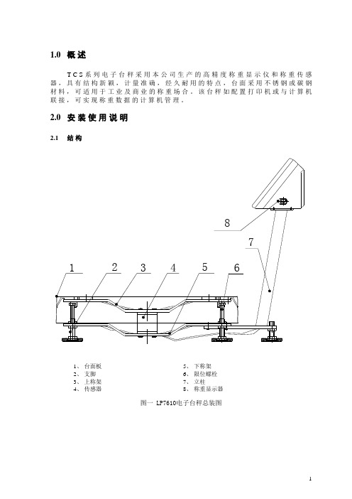
1.0
TC S系列电子台秤采用本公司生产的高精度称重显示仪和称重传感器,具有结构新颖,计量准确,经久耐用的特点,台面采用不锈钢或碳钢材料,可适用于工业及商业的称重场合。该台秤如配置打印机或与计算机联接,可实现称重数据的计算机管理。
精创STC使用说明书

精创STC-9200 使用说明书一.主要功能及特点:1.制冷,化霜,风机控制多种方式供选择;2.用户菜单与管理者菜单分开设置,既方便普通用户操作,又为高级管理者留有充分的调节余地;3.回差控制方式;温度显示分辨率0.1;4.多种保护和报警方式选择;5.具有COPYKEY功能(可选配)。
二.主要技术参数:1.测温范围:-50~50℃控温范围:-50~50℃2.电源电压:220V AC 50HZ3.整机功耗:<5W4.环境温度:0℃~+60℃5.相对温度:20%~85%(不可结霜)6.精度:±1℃7.整机尺寸:75 ×34.5 × 85 (单位:毫米)8.安装孔尺寸:71 × 29(单位:毫米)9.压缩机继电器容量:8A/220VAC10.风机,化霜继电器容量:8A/220VAC11.数码显示:三位数码管+负号位+状态指示灯(设置灯;制冷灯;化霜灯;风机灯)三.指示灯四.按键功能及设置方式:五.参数项清单六.功能介绍:1.压缩机;A.电热化霜状态下,风机延时设置为正:启动条件;当满足条件a) . b) 或者满足条件a) . c) 时,压缩机继电器吸合。
a)压缩机延时超过设定的延时时间。
b)库温高于设置温度,强制制冷开始。
c)非化霜状态下,库温高于设置温度+回差设置值(当风机延时为负值时,在满足其他启动条件且压机已经运行完延时数值的绝对值后压缩机继电器吸合)关闭条件:满足以下条件之一,压缩机继电器断开◇库温低于设置温度◇化霜开始时◇强制制冷结束B.热气化霜状态下:启动条件;当满足条件a) . b) 或者满足条件a) . c) 或者a) . d)时,压缩机继电器吸合。
a)压缩机延时超过设定的延时时间。
b) 非化霜状态下,库温高于设置温度+回差设置值c)库温高于设定温度强制制冷开始。
d)化霜时(当风机延时为负值时,在满足其他启动条件且压机已经运行完设定的延时数值的绝对值后压缩机继电器吸合。
称重传感器、力传感器技术服务手册

低温:使用在温度低于-30℃的场所,如冷冻试验。 5 按准确度级别分类
根据传感器的综合性能分为 A、B、C、D 四个级别 6 按结构分
1)柱式;2)剪切梁式;3)平行梁式;4)板环式;5)S 型;6)弯曲梁式等 五、称重传感器的基本应用
主要应用在各种电子衡器、工业控制领域、在线控制计量、安全过载报警、材料实验机等领域。 1)、电子汽车衡;2)、电子台秤;3)、电子叉车秤;4)、动态轴重秤;5)、电子吊钩秤;6)、电子计 价秤;7)、电子钢材秤;8)、电子轨道衡;9)、连续累计自动衡器;10)、重力式自动衡器;11)、自动分 检衡器;12)、称重模块(用于料斗秤、配料秤、罐装秤及其工业领域)
与所加的激励电压有关,所以额定输出的单位以 mV/V 来表示。并称之为灵敏度。
*灵敏度允差
传感器的实际稳定输出与对应的标称额定输出之差对该标称额定输出的百分比。例
如,某称重传感器的实际额定输出为 2.002mV/V,与之相适应的标准额定输出则为
2mV/V,则其灵敏度允差为:((2.002 – 2.000)/2.000)*100% = 0.1%
传感器的线性误差、滞后误差以及在规定温度范围内由于温度对灵敏度的影响所引起的误差等的总和不能
超过误差带 δ。这就允许制造厂对构成计量总误差的各个分量进行调整,从而获得期望的准确度。
称重传感器按转换方法分为光电式、液压式、电磁力式、电容式、磁极变形式、振动式、陀螺仪式、
电阴应变式等 8 类,以电阻应变式使用最广。
所示:
L
L
F
F
D d
S型称重传感器
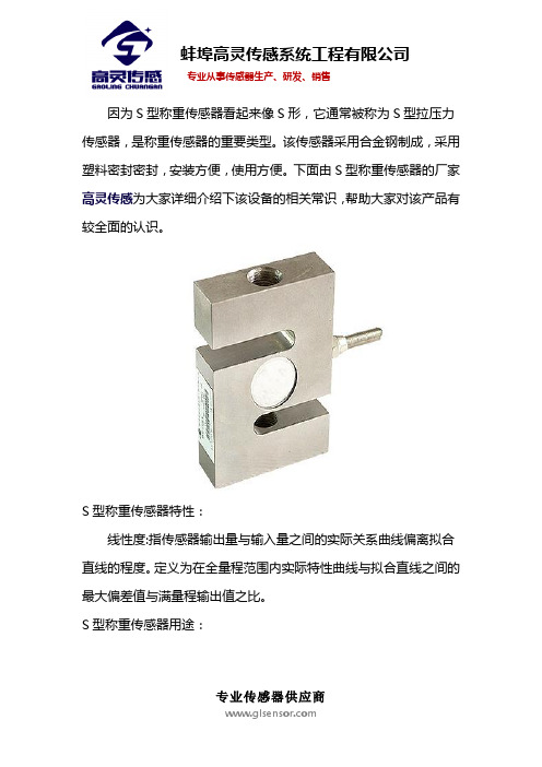
因为S型称重传感器看起来像S形,它通常被称为S型拉压力传感器,是称重传感器的重要类型。
该传感器采用合金钢制成,采用塑料密封密封,安装方便,使用方便。
下面由S型称重传感器的厂家高灵传感为大家详细介绍下该设备的相关常识,帮助大家对该产品有较全面的认识。
S型称重传感器特性:
线性度:指传感器输出量与输入量之间的实际关系曲线偏离拟合直线的程度。
定义为在全量程范围内实际特性曲线与拟合直线之间的最大偏差值与满量程输出值之比。
S型称重传感器用途:
S型称重传感器,选用进口高精度,高稳定性压力传感器芯体,采用电子束焊接,将压力充油部件与不锈钢外壳焊接为一体,由于硅压阻敏感芯片上输出的电压信号与作用下的压力有良好的线性关系,经过本公司的高可靠性放大电路和精细的外部补偿,可实现对被测压力数据的准确测量,再将传感器的压力数据转。
S型称重传感器特性外形尺寸:
蚌埠高灵传感系统工程有限公司在自主创新的基础上开发生产出力敏系列各类传感器上百个品种,各种应用仪器仪表和系统,以及各种起重机械超载保护装置,可以广泛应用于油田、化工、汽车、起重机械、建设、建材、机械加工、热电、军工、交通等领域。
公司除大规模生产各种规格的高精度、高稳定性、高可靠性常规产品外,还可根据用户具体要求设计特殊的非标传感器,以满足用户的特殊要
求。
如果您想进一步的了解,可以直接点击官网高灵传感进行在线了解。
XK3101XS型称重数传器和XK3101DS型称量接收显示器说明.
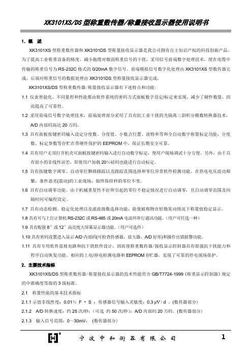
XK3101XS/DS型称重数传器/称量接收显示器的技术性能符合GB/T7724-1999《称重显示控制器》规定的中准确度等级的3级标准。
2.1称量性能的基本技术指标
2.1.1示值非线性度:0.01%F•S;传感器信号输入灵敏度:0.3μV /d。(数传器部分)
2.1.2A/D转换速度:约25次/秒;(可选约50次/秒);A/D内部码20万码。(数传器部分)
4
XK3101XS型称重数传器原理框图
XK3101DS型称量接收显示器接收由XK3101XS发送经电缆传输的RS-232C格式0/20mA电流信号。此信号的内容是与称量信号有关的模数转换值。它由带隔离的串行通讯接口、模拟量输入及模数转换器(特殊用途时)和定值报警继电器等组成,其原理框图如下图所示:
XK3101DS型称量接收显示器原理框图
设定分度数、分度值等
+7
A/D码直接显示(应EEPROM键一直按下)
+8
标定和称量内部码显示
7.4 DIP开关说明
由于本接收显示器可面板数字密码设置进入设定或标定等全部操作,因此不用拨动DIP开关。DIP开关的设置主要用来供生产厂家初始化参数设置、方便调试、检验和用户维护以及用户忘记密码时,进入设置参数操作模式来显示已设置的密码。要拨动开关必须打开机壳的盖板。
7.2.5“↑”键,在设置数据时,按一下此键可使显示器个位数加1递增。在XK3101DS-L累加(打印)接收显示器中此键除加1递增外还用来打印已累加的次数和累加值。
7.3密码设置说明
密码以“ ”为提示符,由1~5位阿拉伯数字组成。供方产品出厂时的密码默认值是“80000”,密码可由用户重新定义和修改。为了有利于记忆,本显示器的密码只有一个,而进入相应设定或标定等操作时,应加上规定的常数。具体的密码由如下表定义:
- 1、下载文档前请自行甄别文档内容的完整性,平台不提供额外的编辑、内容补充、找答案等附加服务。
- 2、"仅部分预览"的文档,不可在线预览部分如存在完整性等问题,可反馈申请退款(可完整预览的文档不适用该条件!)。
- 3、如文档侵犯您的权益,请联系客服反馈,我们会尽快为您处理(人工客服工作时间:9:00-18:30)。
S-Type Load CellModel STCCeltronFEATURES•Capacities: 25 to 5000kg, 250 to 40Klb •Alloy steel construction •Stainless steel available•Bi-direction(tension/compression)•Rationalized output•NTEP Class III 5000S, lllL10000 approval from 250lb to 20KlbOPTIONAL FEATURE•FM approval availableDESCRIPTIONS Type load cell as the name indicated can be easily identified by S-shaped body.They can be loaded either in tension or compression, and used for single or multiple-cell application if the output is rationalized.STC is made of alloy or stainless steel,sealed to IP67 providing excellent protection against moisture and humidity.APPLICATIONS•Electro-mechanical conversion scales •Silo/hopper/tank weighing •Crane scales •Fork-lift scales •Dosing/filling•Universal material tester •Tensile/pulling force measurementModel STCS-T ype Load Cell Celtron OUTLINE DIMENSIONSCAPACITY L W W1H T25/50/75kgmm50.8 26.712.763.5M6 x 1.0 (inch) 2.00 1.050.50 2.50100/150kgmm50.822.9219.176.2M10 x 1.5 (inch) 2.000.90.75 3.00250/300lbmm50.8 26.712.776.2(inch) 2.00 1.050.50 3.003/8-24UNF250kg 500/750lbmm50.830.419.176.2 M12 x 1.75 (inch) 2.00 1.20.75 3.001/2-20UNF500/750kgmm50.825.419.176.2M12 x 1.75 (inch) 2.00 1.000.75 3.001K/1.5Klbmm50.8 26.119.176.2(inch) 2.00 1.030.75 3.001/2-20UNF1000/1500kg 2K/2.5K/3Klbmm50.8 31.825.476.2M12 x 1.75 (inch) 2.00 1.25 1.00 3.001/2-20UNF5K/7.5Klbmm76.231.825.4107.9(inch) 3.00 1.25 1.00 4.253/4-16UNF2000/2500/5000kgmm76.238.131.8100.4M20 x 1.5 (inch) 3.00 1.50 1.25 3.9510Klb mm88.931.825.4120.7(inch) 3.50 1.25 1.00 4.753/4-16UNF15Klbmm101.638.131.8139.7(inch) 4 1.50 1.25 5.501-14UNS20Klbmm12755.750.8177.8(inch) 5 2.1927.0011/4-12UNF40Klbmm152.469.963.5254.0(inch) 6.00 2.75 2.5010.0011/2-12UNFWiring diagram+ Excitation Red- Excitation Black+ Signal Green- Signal WhiteModel STCCeltronS-T ype Load CellSPECIFICATIONS*Capacities 250-20Klbs **Stainless steel availableAll specifications listed subject to change without notice.FM ApprovalIntrinsically Safe: Class I, II, III; Div. 1 Groups A-G Non-Incendive: Class I; Div. 2 Groups A-DPARAMETERVALUEUNITNTEP/OIML Accuracy class NTEP III & IIIL Non-Approved Maximum no. of intervals (n)III 5000single*IIIL 10000single*2000Y = E max /V min100005000Maximum availableStandard capacities (E max )25, 50, 75, 100, 250, 500, 750, 1000, 1500, 2000, 2500, 5000kgStandard capacities (E max )250, 300, 500, 750, 1K, 1.5K, 2K, 2.5K, 3K, 5K, 7.5K,10K, 15K, 20K, 40KlbsRated output-R.O.3.0mV/VRated output tolerance 0.25±%of rated output Zero balance 1±%of rated output Non linearity 0.0200.020 (SS: 0.05) ±%of rated output Hysteresis0.0200.020 (SS: 0.05)±%of rated output Non-repeatability0.020±%of rated output Creep error (20 minutes) 0.030±%of rated output Zero return (20 minutes)0.030±%of rated output Temperature effect on min. dead load output 0.00150.0026±%of rated output/°C Temperature effect on sensitivity 0.00100.0015±%of applied load/°CCompensated temperature range -10 to +40°C Operating temperature range -20 to +60°C Safe overload 150% of R.C.Ultimate overload300% of R.C.Excitation, recommended 10Vdc or Vac rms Excitation, maximum 15Vdc or Vac rmsInput impedance 385±5Ohms Output impedance 350±3Ohms Insulation resistance >5000Mega-OhmsConstructionNickel plated alloy steel**Environmental protection IP67Vishay Precision GroupDisclaimerALL PRODUCTS, PRODUCT SPECIFICATIONS AND DATA ARE SUBJECT TO CHANGE WITHOUT NOTICE.Vishay Precision Group, Inc., its affiliates, agents, and employees, and all persons acting on its or their behalf (collectively, “Vishay Precision Group”), disclaim any and all liability for any errors, inaccuracies or incompleteness contained herein or in any other disclosure relating to any product.The product specifications do not expand or otherwise modify Vishay Precision Group’s terms and conditions of purchase, including but not limited to, the warranty expressed therein.Vishay Precision Group makes no warranty, representation or guarantee other than as set forth in the terms and conditions of purchase. To the maximum extent permitted by applicable law, Vishay Precision Group disclaims (i) any and all liability arising out of the application or use of any product, (ii) any and all liability, including without limitation special, consequential or incidental damages, and (iii) any and all implied warranties, including warranties of fitness for particular purpose, non-infringement and merchantability.Information provided in datasheets and/or specifications may vary from actual results in different applications and performance may vary over time. Statements regarding the suitability of products for certain types of applications are based on Vishay Precision Group’s knowledge of typical requirements that are often placed on Vishay Precision Group products. It is the customer’s responsibility to validate that a particular product with the properties described in the product specification is suitable for use in a particular application.No license, express, implied, or otherwise, to any intellectual property rights is granted by this document, or by any conduct of Vishay Precision Group.The products shown herein are not designed for use in life-saving or life-sustaining applications unless otherwise expressly indicated. Customers using or selling Vishay Precision Group products not expressly indicated for use in such applications do so entirely at their own risk and agree to fully indemnify Vishay Precision Group for any damages arising or resulting from such use or sale. Please contact authorized Vishay Precision Group personnel to obtain written terms and conditions regarding products designed for such applications.Product names and markings noted herein may be trademarks of their respective owners.。