
齿条安装手册
4.40 4.83 10.50 25.00 30.30 50.00 -
9.50 11.10 22.38 44.85 89.71 -
10.67 70.60 -
19.20
120.00
在齿条吊装的旋转半径标记警示符号或是警示带。在搬运和吊装时,该区 域是禁止人员进入的。 启运之前一定要检查搬运路线的滑倒危险,或是其他的干扰,尽量做到安 全。 启运之前一定要确定齿条的整体尺寸所允许的安全吊装。可能遇到的障碍物需要移开或是绕 行。
模数 长度 (mm) 200 250 500 1000 1500 2000 3000 1 1.5 1.591 2 2.5 3 3.183 4 5 6 8 10 12
0.41 0.82 1.64 -
0.51 1.03 2.06 4.11 -
0.39 0.78 1.55 -
0.85 1.00 2.20 4.40 6.15 8.80 8.49
Page Name released 4 01.06.05 01.06.05 20 Schell Lorch
齿条,伺服系统装配方案-
其他标识和符号
☞
☺
该符号标明,请按照要求去做。 指示您合理的简化和改进。 保养:建议最佳操作
安全
识别:显示齿条的说明 贮存:关于正确贮存齿条的信息。
齿条的装配和安装等工作,需要技术熟练,有相关经验和知识的人员操 作。 拆箱和搬运齿条时必须佩戴安全帽,护目镜,防护手套和安全鞋。如果重量 超过 8 公斤,两人合作或是吊车是必要的。如果长度超过 1 米,必须 2 人合作拆箱和搬运, 这样会避免齿条弯曲变形和错误姿势造成人员伤害。吊车驾驶员必须有相关资质。齿条的运 输必须得到适当的保护,如果必要,在齿条端部做明显的标记区分。 ☺ 下表显示的是各种齿条的质量。长度取整数部分。该质量代表齿条模数和长度。 齿条质量 kg
产品编号 ☺ .齿条表面标识有编号
☺
例如:用于拼接的齿条
5
Documented ProcedureBPA
MPZ 001
文件程序
Department Rev. Index Date TB C 25.05.09
4100-001-06.05
Page Name released 6 01.06.05 01.06.05 20 Schell Lorch
直接接触齿条必须戴手套,因为齿条(特别是斜齿齿条)的边缘非常 锋利。
为了避免伤害,安装台的高度必须适合操作工的身高。需要一个可以调节高 度的安装台来适合不同身高的操作工。
一定要提供合适的支架在安装台上,以防止手和手指在放置中齿条过程中受 到挤压或擦伤。 齿条放置的时候要考虑齿条的重心所在,否则可能导致机台倾斜或者齿条滑 落。后果造成四肢撞伤。在齿条放置区可以考虑增加额外的支撑臂以防台面弯曲。 合适身高的装配工会使装配螺栓更加轻松。此外选择合适的扳手能够保护装 配工的手腕免受撞击。这些工作环境的准备是必要的,可以避免工作中受伤。 没有戴手套千万不要接触齿条,装配工作后请洗手,因为齿条表面涂有防锈 油。 如果齿条小于 1 米必须用销钉固定,然后锁紧螺栓。
Байду номын сангаас
齿条,伺服系统装配方案-
目录 公司地址….……………………………………………………………………………………....2 安全须知…......................………………........................……………………………………..3 符号…...…………………………………………….......………………………………………..3 安全…………………………………………………………..….…………………………….....4 产品编号…………………………………………………….…………………………………. ..5 识别 ……………………………………………………………………………………………....6 说明 ….………………………………………………………………………………………....6 应用………………………………………………………………….............…………………..6 运输和操作…………………………………………………..........................................……. 7 贮存………………………………………………………………………….................………..7 安装准备………………………………………………….................................................…..7 安装说明….…………...................................................……………………………………. 8 接触面…………………………………….....................................…………………………...8 定位 ……………………………………..........................…………………………………..11 接触面和支撑面………………..……........................................................................…….12 定位………………………………………............................………………………………...13 安装减速箱………………………………………..........................................……………...14 啮合齿轮副…………………………………….…......................................………………..15 最后检查…………………………………………............................………………………..15 齿轮/齿条运行的前提条件……..…………….................................................................. 16 启动润滑系统…………………………….……….......................................................….. 16 维护………………………………………............................………………………………. 17 停止设备运转,维护.………………........................................................................….. 17 目视检查……………………………………..................................……………………….. 17 检查润滑系统………………………......................................................................…….. 18 维护后重启动……………………….....................................................................…….. 18 故障列表(排除办法)……………….................................................………………….. 18 拆解……………………………………………….............................………………………. 19 准备………………………………………………...................................………………….. 19 拆卸齿条………………………………………….....................................................…….. 19 润滑器………………………………………........................……………………………….. 19 齿轮齿条驱动的润滑…..………….........................................................................…….. 19 废物处理…………………………………….....................………………………………….. 20 润滑油……………………………………………………………...................................….. 20 密封件……………………………………………………………….....................………….. 20 金属……………………………………………………………………........................…….. 20 软管…………………………………………………………………............................…….. 20 毛毡齿轮………………………………………………………............................................ 20
2
Documented ProcedureBPA
MPZ 001
文件程序
Department Rev. Index Date TB C 25.05.09
4100-001-06.05
Page Name released 3 01.06.05 01.06.05 20 Schell Lorch
齿条,伺服系统装配方案-
亚特兰驱动系统
齿条和齿轮驱动
1
Documented ProcedureBPA
MPZ 001
文件程序
Department Rev. Index Date TB C 25.05.09
4100-001-06.05
Page Name released 2 01.06.05 01.06.05 20 Schell Lorch
齿轮齿条安装的技术要求
齿轮齿条安装的技术要求齿轮和齿条是传动机构中常用的组件。
他们之间的配合是非常重要的,正确的安装方式和技术,可以确保传动机构的工作效率和稳定性。
下面就是齿轮齿条安装的技术要求。
1.齿轮与轴的匹配尺寸匹配:齿轮的孔径和轴的直径应匹配,并且应该避免过松或者过紧。
如果过松,会使得齿轮在工作中产生松动,导致传动机构的稳定性不够,工作效率不高;如果过紧,不仅影响安装的顺利进行,而且齿轮在工作中由于摩擦过大而导致过热,最终损坏。
形位匹配:正确的位置和方向是齿轮安装的关键,如果有一定误差可能会影响传动系统的工作效率。
在安装过程中需要确保齿轮的中心线和轴的中心线是处于同一直线上。
配合间隙:在齿轮安装到轴上之前,需要测量两个齿轮的配合间隙,确保这个间隙在工作时不会过大或过小,当齿轮在运动时还能保持良好的配合,以确保传动效率在工作期间的稳定。
啮合:啮合是指齿轮和齿轮之间的互相接触。
然而,在安装过程中,必须确保齿轮齿条之间的啮合正确,否则传动机构的工作效率和稳定性将受到很大的影响。
3.齿轮的润滑在齿轮与齿轮之间安装过程中,必须保证齿轮的润滑充分,以减少齿轮的磨损和摩擦。
在安装齿轮的同时,应该清洁润滑脂,并确保润滑油脂能够充分覆盖齿轮的齿面,避免摩擦过大导致磨损过度。
1.齿条的选择和安装齿条和齿轮之间的啮合是非常重要的,齿条的选择和安装可以影响传动机构的工作稳定性,必须采取以下步骤:齿条的选用:选用型号和规格适当的齿条。
在选择齿条时,应考虑齿条和齿轮之间的啮合,以及齿条在工作时的运动状态。
齿条的安装:在安装齿条之前,应先确保齿条的平整度和表面的光滑度。
安装时,应将齿条倾斜一定角度,使其与齿轮的斜齿面啮合。
啮合间隙应该在这个过程中被准确测量,并确保齿条的端部对齐。
润滑对于齿条和齿轮之间的啮合和运动至关重要。
正确的润滑方法可以减小齿条的磨损和摩擦,同时也可以提高齿轮的工作效率。
在安装齿条的同时,也要施加适量的润滑脂,使其充分覆盖齿条和齿轮的表面,从而减小摩擦和磨损。
齿条安装

- 亞特蘭大
2
Racks - 齒條
齒條理論長度
lstraight mn Z
mn lhelical cos( ) Z
Z β mn = 齒數 = 斜齒角度 = 模數
銑削到 3000mm 磨削到 1500mm
- 亞特蘭大
3
Racks - 齒條
齒條連接和安裝孔的距離:
m z L n
m=8 0,2 0,08 0,03
不要忘記溫度會影響齒條的長度 如果 Δt=10° C 然後 Δl/1000 = 0,11 mm !!!
- 亞特蘭大
7
Racks - 齒條
整體節距誤差 (GTf / 1000 mm)
Q6 Q8 Q9 Q10
m=2 0,073 0,146 0,197 0,287
m=3 0,080 0,153 0,217 0,303
950 N/mm² 650 N/mm²
調質
500...1000 250...1000 500...2000 500...1000 250...1000 250...3000
-
-
(øh11)
1...3 1...3 2...6
8 e 27 10 e 27 9 e 27
650 N/mm²
-
(øh9)
26. ... 47. ...
標準齒條的應用
Standard rack application
- 亞特蘭大
20
-
- 亞特蘭大
6Hale Waihona Puke Racks - 齒條精度性 / 安裝 / 噪聲 要把齒條安裝在位置才能測量齒條的精度性! 珠球測量的誤差 (8 e --)
27 25 23/24
艾特科2R系列齿条传动执行器安装维护手册说明书

Installation & Maintenance ManualTRIAC2R Series Actuators:Attention: Instructional videos on some of the information provided below can be found on our website (/videos/).1. Installation of Actuator:Triac actuators are mounted directly to valves or adapted to the valve by means of an intermediate bracket andcoupler. The coupler adapts the output of the actuator to the valve shaft. Standard mounting kits provide mounting of the actuator in the direction of the pipe. Pipelines can be horizontal, vertical, or other positions. When mounting the actuator to a valve using a mounting kit, the piniondrive, coupling device and valve stem should be centered and concentric to prevent any side loading to the bottom pinion radial bearing and valve stem seal area. After mounting, it may be necessary to adjust the end of travel stop for proper open or closed valve position.Pneumatically stroke the actuator several times to assure proper operation with no binding of the coupler.2. Air Supply:Pneumatic piping to the actuator and associated accessories should follow the best practices for instrument pneumatic piping systems, ie line free of water, oil, pipe sealant or other contaminants. The operating medium is to be filtered dry air or inert gas which is filtered to 50 micron particles size or less. It is extremely important that the actuator be powered with the proper air pressure and air volume. Maximum working pressure is 150 PSI.The spring housing on spring return actuators, if not piped, will breathe through the right hand port. It’s important that it not be exposed to a corrosive atmosphere. Please contact Triac Controls for possible solutions if this condition exists.3. Lubrication:Triac actuators are factory lubricated for life and additional lubrication is not normally required. However, for actuators performing 100,000 cycles or more, an oil mist lubricator is recommended. Oil mist lubrication requires a mineral oil type ISO VG32 Class 1 for usage in temperature range 15 to 158 Deg. F. Oil mist lubricator must be set to the lowest setting. Once begun, the oil mist lubrication cannot be discontinued.Caution: If the actuator is equipped with a pneumatic positioner or pneumatic controller, oil mist lubricated air cannot be used unless the instrument manufacturer indicates that the instrument is compatible with lubricated air.Description Section Installation of Actuator 1Air Supply 2Lubrication 3Travel Adjustment 4Spare Parts 5 Operation – Double Acting 6 Operation – Spring Return FCW 7Disassembly Procedures 8Assembly Instructions 9Actuator Testing 10Cycling of infrequently used actuator 11 Bill of Materials 12Service 13Installation & Maintenance Manual4. Travel Adjustment:The Triac 2nd generation rack & pinion actuators have travel stop adjustments in both the clockwise and counterclockwise directions. The 5 degrees overtravel feature providesadjustments from -5 degrees to +5 degrees at the 0 degree clockwise position and from 85 degrees to 95 degrees at the 90 degree counterclockwise position.All actuated valves require accurate travel-stop adjustments at both ends of the stroke to obtain optimum performance and valve seat life. The accumulation of tolerances in the adaption of actuators to valves is such that there must be a range of adjustment for both ends of the stroke to achieve the expectedperformance. See the valve manufacture’s IOM on how the travel should be adjusted.∙ Ball & Plug Valves require precise adjustment at the open and closed position. This is to protect theseat from the flow media and to assure absolute shut-off in the closed position.∙ Butterfly Valves require precise adjustment at the open and closed position. This is to assure full shut-off, to prevent disc overtravel which can damage the seat in the closed position, and to assure maximum flow in the open position.∙ Tee Assemblies, where two valves are operated in tandem through a single operator, (3-wayconfiguration) require precise adjustment at both ends of the stroke. This is to assure the seating of both valves.5. Spare Parts:Actuator SizeBuna Repair Kit -20°F to 175°F Viton Repair Kit 0°F to 300°F Low TempRepair Kit-45°F to 175°FSpringCartridges(each)2R40 2RKB0040 2RKV0040 2RKLT0040 SP20040 2R80 2RKB0080 2RKV0080 2RKLT0080 SP20080 2R130 2RKB0130 2RKV0130 2RKLT0130 SP20130 2R200 2RKB0200 2RKV0200 2RKLT0200 SP20200 2R300 2RKB0300 2RKV0300 2RKLT0300 SP20300 2R500 2RKB0500 2RKV0500 2RKLT0500 SP20500 2R850 2RKB0850 2RKV0850 2RKLT0850 SP20850 2R1200 2RKB1200 2RKV1200 2RKLT1200 SP21200 2R1750 2RKB1750 2RKV1750 2RKLT1750 SP21750 *Seal Kits also available, but Complete Repair Kits are recommendedInstallation & Maintenance Manual6. Operation – Double Acting: CCW:Air is supplied to Port A forcing the pistons away from each other (toward ends) which rotates the drive pinion counterclockwise and exhausts the air out of Port B.CW:Air is supplied to Port B forcing the pistons toward each other (toward center) which rotates the drive pinion clockwise and exhausts the air out of Port A.7. Operation – Spring Return (Fail CW): CCW:Air is supplied to Port A forcing the pistons away from each other (toward ends), which rotates the drive pinion counterclockwise, compresses the springs and exhausts air out of Port B. FAIL CW:Air failure (loss of pressure) allows the compressed springs to force pistons toward each other (toward center), which rotates the drive pinion clockwise and exhausts air out of Port A.*(Unit is capable of failure in counterclockwise direction by reversing pistons inside of housing.)Installation & Maintenance Manual 8. Disassembly Procedures:CAUTIONBefore removing any components of the actuator, ensure thatall pneumatic and electrical power supplies are disconnected.8.1 Removal of Travel Stops:Disconnect air supply and electric to de-pressure the actuator. Release the lock nuts and unscrewboth travel stops and seals, which are located at the top of the actuator body on the side. In the case of spring return valves make sure that the actuator is in the failed position before removing theactuator8.2 Removal of End Caps:Spring Return Units:Loosen all end cap bolts evenly, to allow the springs to push the end caps out from the body. Thesprings are contained on spools and the tension will be relaxed when the end cap is removed.Always use caution when removing springs.Double Acting Units:Loosen and remove the end cap bolts evenly on both end caps. Using a rubber mallet rotate the end cap slightly, gaining access to the edges of the end cap. Use the rubber mallet to remove the end cap evenly.8.3 Removal of Pistons:Rotate the pinion using a wrench to drive the pistons apart until they are free of the actuator body. 8.4 Removal of Pinion:Remove the snap ring, thrust washer and thrust bearing from the top of the pinion. Carefully remove the pinion from the cylinder body through the bottom. The travel stop cam will not fit through thebottom bore. It will slip off the pinion prior to the pinion removal. Take care to ensure the pinion does not damage the body.9. Assembly Instructions9.1 Inspection:Check that all components are clean and have not been damaged. Triac recommends that all O-rings, Bearings, Washers, etc are replaced using only Triac replacement parts.Installation & Maintenance Manual9.2Installing the Pinion:Lightly grease the pinion, o-ring grooves and guide bushing groove of the pinion and pinion o-rings with multi-purpose grease. Install the top bearing into the actuator body bearing bore. Fit the top o-ring into the top pinion groove. Fit the bottom guide bushing into the bottom pinion groove. Slip the bottom o-ring into the bottom pinion groove. Carefully insert the pinion into the body until the top of the Pinion is inside the body cylinder. Fit the travel stop cam over the top of the pinion and slide it down until it is engaged with the pinion. (Note: The travel stop cam will engage with the pinion in only one position.)Gently push the pinion up through the body making sure the bottom guide bushing, bottom o-ring & top o-ring stay in their grooves. With the pinion in this position install the thrust bearing washer, the thrust washer and lastly the snap ring. Make sure the snap ring fits properly in the groove.9.3Alignment of Pinion for Correct Piston Installation: Rotate the pinion to the position shown in Fig. 5 (When viewed from the slot at the top of the pinion) ensuring that the machined stop flats are in the correct orientation.9.4Installing the Pistons:Lightly grease the piston o-rings, piston backup ring & guide plate with multi-purpose grease & fit the o-rings, backup ring & guide plate into their respective grooves on the piston. Liberally grease the actuator body bore and the piston rack. Insert the pistons into the bore, one piston in each end with the teeth facing each other (see Figures 2, 3 & 4). (Note: The position of the Piston determines the fail rotation of the actuator).Push both pistons together until they are both in contact with the pinion, so that when the pinion is rotated(Clockwise for FCW, Counter Clockwise for FCCW) thepistons are drawn together. When the pistons are together and the racks are correctly engaged with the pinion, the top pinion drive flats should be several degrees past perpendicular to the body for FCW, parallel to the body for FCCW.9.5Installing the Travel Stops:With the pistons together, screw in the corresponding travel stop assembly complete with nut, washer and seal until it comes into contact with the pinion. Rotate the pinion 90 degrees to drive the pistons apart and screw in the other travel stop until it comes into contact with the pinion. After the end caps are installed (see below) final adjustment is easily made when the actuator has been mounted to its valve, damper or other device, depending on individual requirements. Ensure the nuts are tightened against washer and seal.Installation & Maintenance Manual9.6 End Cap Installation:With the pistons together, lightly grease the end cap o-rings with multi-purpose grease. Grease the ends of the body bore and the end caps. Install the o-rings into the groove in the end caps.Spring Return UnitInstall the correct number of springs for the desired torque output. Place the springs into the pockets of the piston and end cap. Balance the springs across the Pistons.10. Testing:Using compressed air at 80psi-100psi, check the seal areas with soapy water and ensure no bubbles are produced and that the pinion rotates smoothly over its full travel.11. Cycling of infrequently used or stored actuators:Actuators that are not in current use for at least a 3 month period, should be cycled a minimum of ten times. The seal manufacturers recommend this procedure to prevent pre-set of the seals.Installation & Maintenance Manual12. Bill of Materials:Description Qty MaterialRemarks1 Cylinder Body 1 Aluminum Hard Anodized2 Drive shaft/Pinion 1 Steel Electroless Nickel Plated3 Bottom Pinion Bushing*** 1 Nylon4 Bottom Pinion O-Ring*** 1 Nitrile Buna5 Travel Stop Cam 1 SCM21 Phosphate Coated6 Travel Stop Washer 1 PTFE7 Top Pinion Bushing*** 1 Nylon8 Top Pinion O-Ring***# 1 Nitrile Buna9 Pinion Teflon Washer*** 1 RTFE 10 Pinion SST Washer*** 1 304 SST11 Snap Ring*** 1 Steel Electroless Nickel Plated 12 Piston 2 Die Cast Aluminum Dichromate Dipped 13 Guide Plate*** 2 Nylon 14 Piston O-Ring***# 2 Nitrile Buna 15 Piston Guide Band*** 2 PTFE 16 End Cap O-Ring***# 2 Nitrile Buna 17 Hole Sealant 2 Nitrile Buna18 End Cap2 Die Cast Aluminum Epoxy Coated 19 End Cap Bolts 8 304 SST 20 Travel Stop Bolt 2 304 SST 21 Travel Stop Nut 2 304 SST 22 Travel Stop Washer 2 304 SST 23 Travel Stop O-Ring***# 2 Nitrile Buna24 Spring Cartridge Varies Spring Steel Epoxy Coated 25 Dust Plug 2 Polyethylene 26 Position Indicator 1 Polyethylene*** Parts included in Repair Kit (Recommended) # Parts included in Seal KitNote: Spring Cartridges are for spring return actuator onlyInstallation & Maintenance Manual 13. Service:It is the policy of Triac to give the best possible service to our customers. We are happy to assist you in any way we can. If you have any questions about Triac Actuators or other Triac products please contact A-T Controls or your local Triac Distributor.A-T Controls, Inc. • 9955 International Boulevard, Cincinnati, OH 45246 • Phone: (513) 530-5175 • Fax: (513) 247-5462 • A-T Controls product, when properly selected, is designed to perform its intended function safely during its useful life. However, the purchaser or user of A-T Controls products should be aware that A-T Controls products might be used in numerous applications under a wide variety of industrial service conditions. Although A-T Controls can provide general guidelines, it cannot provide specific data and warnings for all possible applications. The purchaser / user must therefore assume the ultimate responsibility for the proper sizing and selection, installation, operation, and maintenance of A-T Controls products. The user should read and understand the installation operation maintenance (IOM) instructions included with the product, and train its employees and contractors in the safe use of A-T Controls products in connection with the specific application.While the information and specifications contained in this literature are believed to be accurate, they are supplied for informative purposes only. Because A-T Controls is continually improving and upgrading its product design, the specifications, dimensions and information contained in this literature are subject to change without notice. Should any question arise concerning these specifications, the purchaser/user should contact A-T Controls.For product specifications go to /。
齿条安装规范

齿条安装规范
齿轮安装
先打水平线,测量水平方向是否一致,然后齿轮染色,行走,查看齿条的咬合面是否完整,进行角度的调整。
可以用厚薄规安装
如果是正时齿轮,只需把凸轮轴齿轮与正时齿上的相应标记对正即可。
如
果是变速箱的变速齿轮,在拆解时就
要注意顺序,或者有相应的发动机分解图,否则不容易装好。
但齿轮安装也是有规律的,比如轴两端如果是滚针轴承,就应有平垫圈,如果是球轴承一般就不用平垫圈,但有时为找平间隙也会装垫圈。
在惰性齿轮两端应有花键垫圈,滑动齿轮两端应有弹性挡圈等。
齿条安装方法
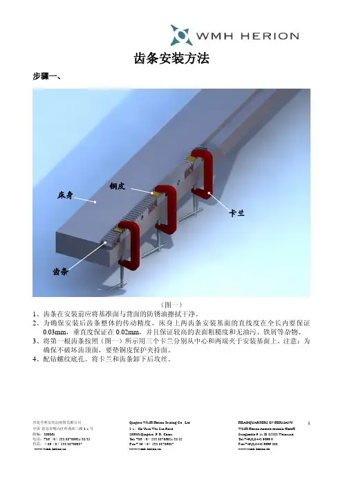
青岛亨利安传动商贸有限公司 Qingdao WMH Herion Trading Co., Ltd.HEADQUARTERS IN GERMANY 中国·青岛市崂山区科苑纬三路2-1号 2-1,Ke Yuan Wei San Road, WMH Herion Antriebstechnik GmbH 邮编:266061 266061Qingdao, P. R..China Stanglmüle 9-11·D-85283 Wolnzach1齿条安装方法步骤一、(图一)1、齿条在安装前应将基准面与背面的防锈油擦拭干净。
2、为确保安装后齿条整体的传动精度,床身上两齿条安装基面的直线度在全长内要保证0.03mm ,垂直度保证在0.02mm ,并且保证较高的表面粗糙度和无油污、铁屑等杂物。
3、将第一根齿条按照(图一)所示用三个卡兰分别从中心和两端夹于安装基面上。
注意:为确保不破坏齿顶面,要垫铜皮保护夹持面。
4、配钻螺纹底孔。
将卡兰和齿条卸下后攻丝。
铜皮 床身 卡兰 齿条青岛亨利安传动商贸有限公司 Qingdao WMH Herion Trading Co., Ltd.HEADQUARTERS IN GERMANY 中国·青岛市崂山区科苑纬三路2-1号 2-1,Ke Yuan Wei San Road, WMH Herion Antriebstechnik GmbH 邮编:266061 266061Qingdao, P. R..China Stanglmüle 9-11·D-85283 Wolnzach2步骤二、(图二)1、将第一根齿条重新安装于床身上,安装上12.9级的紧固螺栓,先不要锁紧。
再次将齿条与床身两基准面靠紧用卡兰夹住。
用扭力扳手根据标准扭矩由中心向外依次锁紧所有螺栓。
2、将针规放于齿槽中,(注意:不同模数齿条选择不同针规,详见下表)将百分表安装于机床移动部件上(如:直线导轨滑块上或滑动导轨滑枕上),测量针规在不同长度上的高度是否一致。
浅谈海洋平台齿条的安装以及焊接工艺要点

焊接烟尘的排放控制措施
选用低尘焊接材料 焊接作业时佩戴防尘口罩 焊接烟尘净化处理设备 定期对焊接烟尘排放进行检测和评估
废弃物的处理与回收利用
废弃物分类:根据性质和危害程度进行分类,如可回收物、不可回收物、有害废弃物等。
废弃物处理:对于可回收物,应进行回收利用;对于有害废弃物,应进行无害化处理;对于不 可回收物,应进行安全处置。
选择原则:与母 材相匹配,满足 使用要求
准备事项:检查 焊接材料的质量、 规格和有效期等
存放要求:符合 焊接材料的储存 和使用规范
焊接方法的确定与操作要点
根据材料和厚度选择合适的焊接方法 确定焊接参数:电流、电压、焊接速度等 准备焊接设备:焊机、焊枪、焊丝等 操作要点:保持焊接姿势、掌握焊接技巧、注意安全防护
单击添加章节标题
Part Two
海洋平台齿条的安 装
安装前的准备工作
确定安装位置和高度
检查齿条的规格和尺寸是 否符合要求
准备安装工具和材料
对安装人员进行培训和安 全交底
安装过程中的注意事项
安装前检查:确保齿条规格、型号与设计相符,无损坏和变形 安装位置:根据设计要求,确定齿条的安装位置,确保其稳定性和安全 性 安装方法:采用合适的安装方法,避免齿条变形或损坏
安装后的检查:安装完成后,对齿条进行检查,确保其符合设计要求
安装后的检查与验收
检查齿条安装位置是否准确 检查齿条与平台支撑的连接是否牢固 检查齿条的直线度和水平度是否符合要求 检查齿条的安装高度是否符合设计要求
Part Three
焊接工艺要点
焊接材料的选择与准备
考虑因素:母材 的化学成分、力 学性能、耐腐蚀 性等
焊接缺陷的预防与处理
预防措施:严格控制焊接工 艺参数、提高操作技能、保
齿条的安装
附录2: 齿条安装 一、安装方式:齿条连接使用时,如果将两根齿条的端面紧贴在一起,连结部的齿距会变小而成为故障的原因。
请参考下面的装配方法,正确组装。
也适用于单根齿条安装。
方法一:用安装块辅助安装齿条1.齿条的定位和固定(用螺旋夹钳与安装面压紧) 建议采用如下夹兰夹紧2.用强度为12.9级的紧固螺栓,根据相应预紧力将第一根齿条紧固。
3.用安装块辅助安装后续齿条,没有安装块可用其中一根齿条代替安装块。
(仅适用直齿齿条)4.用强度为12.9级的紧固螺栓,根据预紧力将第二根齿条紧固,以此类推安装后续齿条。
5.安装后检验齿条的平行度及各齿条之间的平行度,同时还要检验齿条的直线度。
6. 在检验完后,配钻、铰齿条销孔,安装定位销。
方法二:用验棒辅助安装齿条1.选择两个直径相同的验棒,如图放在齿条连接处,为确保精度,建议使用的圆柱销直径见下表:不同模数所用验棒直径一览表模数验棒直径﹙mm﹚1 1.71.52.72 3.352.5 4.23 54 6.75 8.356 10.558 1410 16.7112 202.用卡尺或千分尺测量两圆柱销外侧距离达到2π·m+d二、注意事项起动前请确认下列各项内容:(1)齿轮的装配是否确实(2)轮齿接触是否偏向一端(3)是否有适当的侧隙(请避免无侧隙使用)(4)有没有足够的润滑注1:为使紧固螺钉在剪切方向不承受负荷,请同时使用销钉固定齿条。
注2:侧隙是齿轮平滑旋转所必需的间隙。
侧隙太小容易造成润滑不良,成为生成磨损的原因。
另外,因为两齿面相互接触,有可能增大噪音。
齿轮精度越高,侧隙就可能调整的越小。
但要避免在无侧隙的状态下使用。
标准齿条设计有固定的侧隙,装配时,只需根据组装距离(组装距离公差为H7~H8)进行组装。
齿条单体的侧隙(齿厚减少量)单位:mm精度等级(KHK R 001)1级3级4级5级模数(m)或齿距(CP)未经调质调质处理m0.5 -0~0.07 0.02~0.10 --m0.8、 CP2.5 0~0.05 0~0.08 0.03~0.12 0.03~0.14 0.03~0.14 m1 0~0.05 0~0.10 0.03~0.12 0.03~0.14 0.03~0.14 m1.5、 CP5 0~0.05 0~0.10 0.04~0.13 0.04~0.15 0.04~0.15 m2 0~0.05 0~0.10 0.05~0.14 0.05~0.16 0.05~0.16 m2.5 0~0.05 0~0.10 0.06~0.16 0.06~0.18 0.06~0.18 m3、 CP10 0~0.05 0~0.10 0.07~0.18 0.07~0.20 0.07~0.20 m4 -0~0.10 0.08~0.22 0.08~0.24 0.08~0.24 m5、 CP15 -0~0.10 0.09~0.24 0.09~0.26 0.09~0.26 m6、 CP20 -0~0.10 0.10~0.28 --m8 --0.13~0.32 --m10 --0.15~0.34 --。
齿轮齿条的安装
齿轮齿条的安装简易锥套工具推压挡圈(拆装实训时中间轴总成可不必分解,了解上述安装过程即可)。
③将变速器壳体固定在专用拆装台上,把安装好的中间轴总成放人中问轴孔内,两v 套上中间轴前、后轴承;然后从变速器后端插人倒挡齿轮轴。
④用铜棒将中间轴前、后轴承敲入轴承座孔,应沿轴承外圈四周均匀敲击;然后套上锁片用抓母拧紧(拧紧力矩为147 N·m),用锁片把螺母锁紧,在中间轴后轴承外圈边缘套上挡圈:最后在变速器壳体上分别装上中间轴的前后轴承盖。
⑤用铜棒将例挡敲到安装位置,卡上倒挡齿轮轴锁片;并用螺栓固定锁片;最后在变速器壳体左侧装上倒挡齿轮检查窗孔盖板。
装盖时要装衬垫,衬垫表面涂密封胶液.用涂胶螺栓紧固盖。
⑥按拆卸时相反顺序组装第二轴总成,注意装二、三挡同步器时,将滑动齿套凸出的一面朝向第一轴方向。
⑦将安装好第二轴总成放到变速器壳体里,从第二轴后端套上后轴承,用铜棒轻轻敲击,使轴承靠到第二轴花键部分台肩L,套人里程表的主动齿轮和m套,然后装上挡圈。
⑧在第一轴上压人滚珠轴承,装上轴承外缘档圈。
在第一轴内孔中装人滚针轴承;然后把第一轴装到壳体前端轴承孔中,使第二轴前端轴x对准第一轴轴承孔,用铜棒一边轻轻敲击,一边用手转动第一轴,使轴承平顺装人壳体座孔中。
通过式((6-10)和图6-19可以看出.外啮合齿轮非标准安装时原来的中心距a增大至a’,这时两轮的分度圆不再相切而是分开一段距离,节圆与分度圆也就不再重合,两轮的节圆半径大于各自的分度圆半径,其啮合角。
‘也大于分度圆的压力角a.由式(6-10)可知,中心距和啮合角的关系式为地磅a,cosy=acosa (6一11)当标准齿轮的中心距增大至a’时,必然出现齿侧间隙,如图6-19所示,从而在传动过程中引起两齿廓面的冲击,影响齿轮的传动质量,因此在设计标准齿轮传动时要尽量保证获得标准中心距。
第6章齿枪机构原理与设计1316.4.4齿轮齿条的安装在图6-20中.实线所示为标准Al轮与齿条按照齿轮分度圆与齿条中线相切进行安装,此时齿轮分度圆与节圆重合,齿条中线与节线重合.啮合角等于分度圆的压力角,这种情况称为齿轮齿条的标准安装。
齿条的固定方式
齿条的固定方式齿条是一种常见的机械传动装置,广泛应用于各种机械设备中。
为了确保齿条的稳定运行和传动效果,它需要被固定在相应的位置上。
下面将介绍几种常见的齿条固定方式。
1. 螺栓固定法螺栓固定法是一种常见的齿条固定方式。
它通过将螺栓穿过齿条的固定孔,并与底座或其他固定件紧密连接,以确保齿条的位置稳定。
螺栓材料通常选用高强度合金钢,以确保足够的固定力和耐久性。
2. 焊接固定法焊接固定法是将齿条焊接在底座或其他固定件上。
这种固定方式可以提供更牢固的连接,适用于承受较大载荷或需要更高精度的场合。
在焊接前,需要确保齿条和固定件的表面清洁,并正确选用焊接材料和焊接工艺。
3. 螺母固定法螺母固定法是通过将螺母与齿条的固定孔相匹配,将齿条固定在底座或其他固定件上。
这种固定方式简单易行,适用于较小的齿条或不承受大载荷的场合。
螺母的材料通常选用高强度钢材,并通过正确的拧紧力矩来确保固定的可靠性。
4. 锁紧螺钉固定法锁紧螺钉固定法是通过使用特殊的螺纹结构和锁紧装置,将螺钉固定在齿条的固定孔上。
这种固定方式能够在承受振动和冲击时保持固定的可靠性,适用于高速运动或工作环境较恶劣的场合。
5. 槽孔固定法槽孔固定法是通过将齿条的固定孔设计成槽状结构,然后通过螺栓或其他固定件将齿条固定在底座或其他固定件上。
这种固定方式具有一定的调整性,可以在一定范围内调整齿条的位置。
槽孔的设计和尺寸需要根据具体的应用要求进行合理选择。
以上是几种常见的齿条固定方式。
在选择固定方式时,需要考虑齿条的尺寸、形状、材料以及所承受的载荷等因素。
同时,固定方式的选择也会影响到齿条的安装和维护工作。
因此,在实际应用中,需要根据具体情况进行综合考虑和选择,以确保齿条的稳定运行和传动效果。
齿条安装手册
Documented ProcedureBPA
MPZ 001
文件程序
Page Name released 4 01.06.05 01.06.05 20 Schell Lorch
齿条,伺服系统装配方案-
其他标识和符号
☞
☺
该符号标明,请按照要求去做。 指示您合理的简化和改进。 保养:建议最佳操作
安全
识别:显示齿条的说明 贮存:关于正确贮存齿条的信息。
齿条的装配和安装等工作,需要技术熟练,有相关经验和知识的人员操 作。 拆箱和搬运齿条时必须佩戴安全帽,护目镜,防护手套和安全鞋。如果重量 超过 8 公斤,两人合作或是吊车是必要的。如果长度超过 1 米,必须 2 人合作拆箱和搬运, 这样会避免齿条弯曲变形和错误姿势造成人员伤害。吊车驾驶员必须有相关资质。齿条的运 输必须得到适当的保护,如果必要,在齿条端部做明显的标记区分。 ☺ 下表显示的是各种齿条的质量。长度取整数部分。该质量代表齿条模数和长度。 齿条质量 kg
4.40 4.83 10.50 25.00 30.30 50.00 -
9.50 11.10 22.38 44.85 89.71 -
10.67 70.60 -
19.20
120.00
在齿条吊装的旋转半径标记警示符号或是警示带。在搬运和吊装时,该区 域是禁止人员进入的。 启运之前一定要检查搬运路线的滑倒危险,或是其他的干扰,尽量做到安 全。 启运之前一定要确定齿条的整体尺寸所允许的安全吊装。可能遇到的障碍物需要移开或是绕 行。