关于轻型直流输电的部分英文文献及翻译
基于VSC的轻型直流输电

!杨 军
随着我国社会主义市场经济改革的不断深入!电力建设施工 企业的改革也已迫在眉睫" 在激烈的市场竞争环境中如何生存# 如何更好地发展!是很多电力建设施工企业和电力改革研究人员 正在进行的重要课题" 各电力建设施工企业加大改革力度!内抓 管理!外抓市场!不断增强企业的竞争能力"其中!作为企业管理重 中之重的安全管理越来越多地被各级管理层所重视!同时也意识 到!只有建立现代企业安全管理体系!科学地建设企业安全文化! 才能成为电力建设施工企业稳定#持续发展的有力保障" 因此!如 何结合本行业和本企业的特点建设富有特色和实用价值的企业
!!"
广东科技 2006.10 总第 160 期
业 界 建设行业专版 水*电*暖*通
科学建设企业安全文安全文化是企业文化的主要分支!只有科学地建设企业安全文化!才 能成为电力建设施工企业稳 定#持续发展的有力保障" 关键词:企 业 安 全 文 化 % 电 力 建 设 企 业 % 发 展 % 保 障 %
!!!!!!!!!!!!!!!!!!!!!!!!!!!!!!!!!!!!!!!!!!!!!!!
母线电压" 这意味着故 障 时 !如 VSC 容 量 允 许 !那 么 轻 型 直 流
4.4 提高配电网电能质量
输电既可向故障系统提供有功功率的紧急支援!又可提供无功
非线性负荷和冲击性负荷使配电网产生电能质量问题!如
企业文化不是一般意义上的文化现象! 企业文化是企业的灵 魂!是企业共享的价值观" 企业文化是一种管理!是发展到高层次 的管理%企业文化是市场经济的产物!企业文化是一种精神现象却 有着深刻的物质基础"
作为企业文化的重要组成部分! 企业安全文化是企业文化的 主要分支" 它既包括保护职工在从事生产经营活动中的身心安全
直流电动机中英文对照外文翻译文献

中英文对照外文翻译文献(文档含英文原文和中文翻译)外文文献:DC Motor CalculationsOverviewNow that we have a good understanding of dc generators, we can begin our study of dc motors. Direct-current motors transform electrical energy into mechanical energy. They drive devices such as hoists, fans, pumps, calendars, punch-presses, and cars. These devices may have a definite torque-speed characteristic (such as a pump or fan) or a highly variable one (such as a hoist or automobile). The torque-speed characteristic of the motor must be adapted to the type of the load it has to drive, and this requirement has given rise to three basic types of motors: 1.Shunt motors 2. Series motors 3. Compound motors Direct-current motors are seldom used in ordinary industrial applications because all electric utility systems furnish alternating current. However, for special applications such as in steel mills, mines, and electric trains, it is sometimes advantageous to transform the alternating current into direct current in order to use dc motors. The reason is that the torque-speed characteristics of dc motors can be varied over a wide range while retaining high efficiency. Today, this general statement can be challenged because the availability of sophisticated electronic drives has made it possible to use alternating current motors for variable speed applications. Nevertheless, there are millions of dc motors still in service and thousands more are being produced every year.Counter-electromotive force (cemf)Direct-current motors are built the same way as generators are; consequently, a dc machine can operate either as a motor or as a generator. To illustrate, consider a dc generator in which the armature, initially at rest, is connected to a dc source E s by means of a switch (Fig. 5.1). The armature has a resistance R, and the magnetic field is created by a set of permanent magnets.As soon as the switch is closed, a large current flows in the armature because its resistance is very low. The individual armature conductors are immediately subjected to a force because they are immersed in the magnetic field created by the permanent magnets. These forces add upto produce a powerful torque, causing the armature to rotate.Figure 5.1 Starting a dc motor across the line.On the other hand, as soon as the armature begins to turn, a second phenomenon takes place: the generator effect. We know that a voltage E o is induced in the armature conductors as soon as they cut a magnetic field (Fig. 5.2). This is always true, no matter what causes the rotation. The value and polarity of the induced voltage are the same as those obtained when the machine operates as a generator. The induced voltage E o is therefore proportional to the speed of rotation n of the motor and to the flux F per pole, as previously given by Eq. 5.1:E o = Zn F/60 (5.1)As in the case of a generator, Z is a constant that depends upon the number of turns on the armature and the type of winding. For lap windings Z is equal to the number of armature conductors.In the case of a motor, the induced voltage E o is called counter-electromotive force (cemf) because its polarity always acts against the source voltage E s. It acts against the voltage in the sense that the net voltage acting in the series circuit of Fig. 5.2 is equal to (E s - Eo) volts and not (E s + E o) volts.Figure 5.2 Counter-electromotive force (cemf) in a dc motor.Acceleration of the motorThe net voltage acting in the armature circuit in Fig. 5.2 is (E s- E o) volts. The resulting armature current /is limited only by the armature resistance R, and soI = (E s- E o)IR (5.2)When the motor is at rest, the induced voltage E o= 0, and so the starting current isI = E s/RThe starting current may be 20 to 30 times greater than the nominal full-load current of the motor. In practice, this would cause the fuses to blow or the circuit-breakers to trip. However, if they are absent, the large forces acting on the armature conductors produce a powerful starting torque and a consequent rapid acceleration of the armature.As the speed increases, the counter-emf E o increases, with the result that the value of (E s—E o)diminishes. It follows from Eq. 5.1 that the armature current / drops progressively as the speed increases.Although the armature current decreases, the motor continues to accelerate until it reaches a definite, maximum speed. At no-load this speed produces a counter-emf E o slightly less than the source voltage E s. In effect, if E o were equal to E s the net voltage (E s—E o) would become zero and so, too, would the current /. The driving forces would cease to act on the armature conductors, and the mechanical drag imposed by the fan and the bearings would immediately cause the motor to slow down. As the speed decreases the net voltage (E s—E o) increases and so does the current /. The speed will cease to fall as soon as the torque developed by the armature current is equal to the load torque. Thus, when a motor runs at no-load, the counter-emf must be slightly less than E s so as to enable a small current to flow, sufficient to produce the required torque.Mechanical power and torqueThe power and torque of a dc motor are two of its most important properties. We now derive two simple equations that enable us to calculate them.1. According to Eq. 5.1 the cemf induced in a lap-wound armature is given byE o = Zn F/60Referring to Fig. 5.2, the electrical power P a supplied to the armature is equal to the supply voltage E s multiplied by the armature current I:P a = E s I (5.3)However, E s is equal to the sum of E o plus the IR drop in the armature:E s = E o + IR (5.4)It follows thatP a= E s I= (E o + IR)I=E o I + I2R (5.5)The I2R term represents heat dissipated in the armature, but the very important term E o I is the electrical power that is converted into mechanical power. The mechanical power of the motor is therefore exactly equal to the product of the cemf multiplied by the armature currentP = E o I (5.6)whereP = mechanical power developed by the motor [W]E o= induced voltage in the armature (cemf) [V]I = total current supplied to the armature [A]2. Turning our attention to torque T, we know that the mechanical power P is given by the expressionP = nT/9.55 (5.7)where n is the speed of rotation.Combining Eqs. 5.7,5.1, and 5.6, we obtainnT/9.55 = E o I= ZnFI/60and soT =Z F I/6.28The torque developed by a lap-wound motor is therefore given by the expressionT =Z F I/6.28 (5.8)whereT = torque [N×m]Z = number of conductors on the armatureF = effective flux per pole [Wb]*/ = armature current [A]6.28 = constant, to take care of units[exact value = 2p]Eq. 5.8shows that we can raise the torque of a motor either by raising the armature current or by raising the flux created by the poles.Speed of rotationWhen a dc motor drives a load between no-load and full-load, the IR drop due to armature resistance is always small compared to the supply voltage E s. This means that the counter-emf E s is very nearly equal to E s.On the other hand, we have already seen that Eo may be expressed by the equationE o = Zn F/60Replacing E o by E s we obtainE s = Zn F/60That is,wheren = speed of rotation [r/min]E s = armature voltage [V]Z = total number of armature conductorsThis important equation shows that the speed of the motor is directly proportional to the armature supply voltage and inversely proportional to the flux per pole. We will now study how this equation is applied.Armature speed controlAccording to Eq. 5.8, if the flux per pole F is kept constant (permanent magnet field or field with fixed excitation), the speed depends only upon the armature voltage E s. By raising or lowering E s the motor speed will rise and fall in proportion.In practice, we can vary E s by connecting the motor armature M to a separately excited variable-voltage dc generator G . The field excitation of the motor is kept constant, but the generator excitation I x can be varied from zero to maximum and even reversed. The generator output voltage E s can therefore be varied from zero to maximum, with either positive or negative polarity. Consequently, the motor speed can be varied from zero to maximum in either direction. Note that the generator is driven by an ac motor connected to a 3-phase line. This method of speed control, known as the Ward-Leonard system, is found in steel mills, high-rise elevators, mines, and paper mills.In modem installations the generator is often replaced by a high-power electronic converter that changes the ac power of the electrical utility to dc, by electronic means.What happens to the dc power received by generator G? When G receives electric power, it operates as a motor, driving its own ac motor as an asynchronous generator!* As a result, ac power is fed back into the line that normally feeds the ac motor. The fact that power can be recovered this way makes the Ward-Leonard system very efficient, and constitutes another of its advantages.Rheostat Speed ControlAnother way to control the speed of a dc motor is to place a rheostat in series with the armature . The current in the rheostat produces a voltage drop which subtracts from the fixed source voltage E s, yielding a smaller supply voltage across the armature. This method enables us to reduce the speed below its nominal speed. It is only recommended for small motors because a lot of power and heat is wasted in the rheostat, and the overall efficiency is low. Furthermore, thespeed regulation is poor, even for a fixed setting of the rheostat. In effect, the IR drop across the rheostat increases as the armature current increases. This produces a substantial drop in speed with increasing mechanical load.中文译文:直流电动机的计算概述现在,我们对直流发电机有一个很好的了解,我们可以开始对直流电动机的研究了。
直流输电论文 王巍

轻型直流输电中的VSC技术摘要:电压源换流器高压直流输电是基于电压源换流器技术的新一代直流输电技术,相比于传统的直流输电技术具有小型、高效,控制灵活的特点,经济效益和环保价值可观,能有效的减少输电线路电压降落和闪变,提高了电能质量。
文章简介了轻型直流输电,介绍电压源换流器的基本原理、控制策略和技术特点。
综述近年来VSC-HVDC 技术发展及其应用前景。
关键词:轻型直流输电电压源型换流器1轻型直流简介和出现背景轻型直流输电即HVDC Light,该技术由ABB公司在上个世纪八、九十年代研制开发的—种新型输电技术。
HVDC Light轻型直流输技术,以电压源型换流器(VSC)为核心,硬件上采用IGBT等可关断器件,控制上采用脉宽调制技术(PWM)以达到具有高可控性直流输电的目的。
传统高压直流(HVDC)输电技术在远距离大功率输电、海底电缆送电、不同额定频率或相同额定频率交流系统之间的联结等场合应用广泛。
但由于传统HVDC 输电技术的换流器采用的是半控型晶闸管器件,存在很多不足。
尽管人们对传统HVDC 输电进行了不断的改造,但这些改进措施均不能从根本上解决HVDC 输电的不足。
近年来,随着风能、太阳能等可再生能源利用规模的不断扩大,同时海上钻井平台、孤立小岛等无源负荷,使得采用交流输电技术或者传统直流输电技术存在很大的不足和缺陷。
因此迫切需要采用更加灵活、经济、环保的输电方式。
随着电力电子技术的发展,特别是具有可关断能力的电力电子器件的发展,如绝缘栅极晶体管(IGBT)、门级可关断晶闸管(GTO)等,促进了HVDC输电技术的一次重大变革。
由于采用全控型可关断器件构成的电压源换流器(VSC)以及脉宽调制(PWM)控制技术为基础,使得电压源换流器直流输电(VSC-HVDC)方式有一些传统HVDC 无法比拟的优点,例如可以向无源网络供电,同时控制有功功率和无功功率,动态补偿母线的无功功率,稳定交流母线电压等,因而也被称为柔性直流输电方式。
关于轻型直流输电的部分英文文献及翻译

英文文献原文A sensorless and simple controller for VSC basedHVDC systemsAbstract: Voltage source converter high-voltage direct current (VSC-HVDC) is a new power transmission technology preferable in small or medium power transmission. In this paper we discuss a new control system based on space vector modulation (SVM) without any voltage line sensors. Using direct power control (DPC) SVM and a new double synchronous reference frame phase-locked loop (DSRF-PLL) approach, the control system is resistant to the majority of line voltage disturbances. Also, the system response has accelerated by using a feed forward power decoupled loop. The operation of this control strategy was verified in a SIMULINK/MATLAB simulation environment. To validate this control system, a 5 kV·A prototype system was constructed. Compared to the original controllers, the current total harmonic distortion (THD), the active and reactive deviations and the DC voltage overshoot were lowered by 2.5%, 6.2% and 8%, respectively. The rectifier power factor in the worst condition was 0.93 and the DC voltage settling time was 0.2 s.Key words: Voltage source converter high-voltage direct current (VSC-HVDC), Space vector modulation (SVM), Direct power control (DPC), HVDC Light1 INTRODUCTIONVoltage source converter high-voltage direct current (VSC-HVDC), controlled by pulse width modulation (PWM), can supply power to both active and passive electrical systems. The introduction of VSC and PWM makes possible fast and flexible control of power flow and more convenient operation of power systems. Besides, this advancement, compared with conventional HVDC, mitigates harmonics in AC current and AC voltage greatly and improves power factors of the connected AC systems (Li GK et al., 2005). VSC-HVDC or HVDC Light, in recent years, have successfully been commercially commissioned in such fields as supplying power to remote isolated loads, empowering urban centers, connecting distributed generation sources, linking two asynchronous electrical power systems, improving power quality, and so on (Asplund, 2000; Li et al., 2003).The advantages of a VSC based HVDC system are (Asplund, 2000): (1) only a small filter is required to filter high frequency signal components;(2) there is no commutation failure problem; (3) reactive power compensation is not required; (4) there is no restriction on multiple in-feeds; etc.There are various control methods for VSC based HVDC systems. Zhang et al.(2002) used the inverse steady state model controller to trace the operating point and adopted two decoupled controlling loops to eliminate the steady state deviation. Chen et al.(2004) proposed a steady-state controller design scheme based on dq0-axis. Zhang et al.(2002) and Chen et al.(2004) assumed that the two terminals of VSC-HVDC have been connected to an infinite bus system. But one terminal of VSC-HVDC may be connected to a generator and, as in Asplund et al. (1997), an HVDC Light system connects the generator (such as an offshore wind farm) to the grid. These strategies focus on control of the HVDC system itself and do not consider the interaction between AC and DC systems. Hu et al.(2004) presented an optimal coordinated control strategy between the generator excitation and VSC-HVDC, whereas the derivation of control law is complicated. Hu et al.(2005) applied a genetic algorithm (GA) to optimize parameters of the controller after determining them. Ooi and Wang (1991) and Zhang and Xu (2001) used a phase and amplitude control (PAC) technique for VSC based HVDC applications. Li GI et al.(2005) proposed a nonlinear control for an HVDC Light system. These methods have used voltage and current sensors.A direct power control (DPC) strategy based on virtual flux, called VF-DPC, provides sinusoidal line current, lower harmonic distortion, a simple and noise-robust power estimation algorithm and good dynamic response (Rahmati et al., 2006). However, the VF-DPC scheme has the following well-known disadvantages (Malinowski et al., 2001; 2004): (1) variable switching frequency (difficulties of LC input filter design), (2) high sampling frequency needed for digital implementation of hysteresis comparators, (3) necessity for a fast microprocessor and A/D converters.Therefore, there is no tendency to implement VF-DPC in industry. All the above drawbacks can be eliminated when, instead of the switching table, space vector modulation (SVM) is applied.DPC is a method based on instantaneous direct active and reactive power control (Malinowski et al., 2004). In DPC there are no internal current control loops and no PWM modulator block. Moreover, the turn-on and turn-off commands of the static switches of the converters are generated by SVM. Use of space vector modulation causes lower current harmonics, relatively high regulation and stability of output voltage and obtains a higher modulation factor relative to sinusoidal modulation (Malinowski et al., 2004). Also, it can easily be implemented in a DSPbased system.Double synchronous reference frame phase-locked loop (DSRF-PLL) based on VF causes this control system to be resistant to the majority of line voltage disturbances. This assures proper operation of the system for abnormal and failure grid conditions.In this paper a new control strategy is proposed for VSC-HVDC. In this strategy, the reactive power and output DC voltage in the rectifier station and the reactive and active powers in the inverter station are controlled, separately. Also, the DPC rectifier equations (Malinowski et al., 2004) have been developed for the inverter. For more accuracy in high power, the second order parameter is included in the rectifier and the inverter equations. Active and reactive power feed forward decoupling are used for accelerating the system response. Finally, DPC is applied to the rectifier and inverter stations of VSC-HVDC.The operation of this control strategy is verified in a SIMULINK/MATLAB simulation environment for steady state, active and reactive power variations, single-line-to-ground faults and unbalanced sources at the rectifier and the inverter stations. Also, this control strategy is applied to a 5 kV ·A prototype system which is verification that this control strategy has a fast response and strong stability.2 CONTROL of VSC BASED HVDC SYSTEM2.1 VSC based HVDC systemVSC-HVDC involves two voltage source converters with the same configuration, linking with a dc transmission line or cable (Fig.1). There are four control variables represented by dcr U ,r q ,i p and i q for this system. In this paper, a rectifier station is chosen to control DC-bus output voltage of rectifier (dcr U ). Also, reactive power (r q ) and inverter station are set to control active power (i p ) and also reactive power (i q ). R c is the equivalent resistance of the transmission cable and can be practically neglected. Thus we may write dcr dci dc U U U ≈= .Fig.1 A physical model for a VSC based HVDC system2.2 Virtual-flux estimator for rectifier and inverterFrom the economical point of view, and for simplicity, more reliability and separation of power stage and control, AC line voltage sensors are replaced by a flux estimator (Malinowski et al., 2004).The basic model of a VSC station is shown in Fig.2. If D a, D b, and D c are the duty cycles of S a, S b, and S c signals, respectively, U dc is the converter DC voltage, and u L α and u L β are line voltage in α-β coordinates, then the related flux of AC voltage, L ψ, can be written as(Malinowski et al., 2004).L L L L L u dt u dt ααββ⎡⎤ψ⎡⎤⎢⎥ψ==⎢⎥ψ⎢⎥⎣⎦⎣⎦⎰⎰ (1) Also, the converter voltage equations in α-β coordinates are: ()21,32S dc a b c u U D D D α⎡⎤=-+⎢⎥⎣⎦(2) ().2S dc b c u U D D β=- (3)Fig.2 Basic model of a voltage source converter2.3 Direct power controlActive and reactive power in the rectifier and the inverter stations are estimated using the line current vectors (),L L i i αβand estimated virtual flux (),L L αβψψin α-β coordinates (Malinowski et al., 2004):(),L L L L p i i αββαω=ψ-ψ (4)().L L L L q i i ααββω=ψ+ψ (5)2.4 Rectifier control designThe full control algorithm of the proposed control system is presented in Fig.3. The DPC-SVM uses closed-loop power control. In the rectifier station, reference reactive power (q refr) is set to zero for unity-power-factor operation. In an ideal case, the active power in the rectifier station and the active power in the inverter station are equal, and no storage elements are needed. Nevertheless, in real systems differences between these active powers are inevitable, and these differences are absorbed by the DC link capacitor and are reflected in fluctuations of the DC link voltage. Thus, the reference active power (p ref r) at the side of the rectifier is the sum of the outer proportional-integral (PI) dc voltage controller and estimated active power in the inverter station (p i).Fig.3 Control scheme for a VSC based HVDC system with the rectifier and inverterstationsAccording to the current direction, the line voltage u Lr can be expressed as the sum of the inductor voltage u Ir, the resistor voltage u Rr and the rectifier voltage u Sr (Rahmati et al., 2006):.Lr Sr Ir Rr u u u u =++ (6)By considering Eq.(1), the estimated virtual fluxes are:()(),Lr est Sr r r u R i dt L i ααααψ=++⎰ (7)()().Lr est Sr r r u R i dt L i ββββψ=++⎰ (8)2.5 Inverter control designIn the inverter station, reference reactive power (q ref i) and reference active power (p ref i) are set to network demand. According to the current direction, the inverter voltage u Si can be expressed as the sum of the inductor voltage u Ii, the resistor voltage u Ri and the line voltage u Li at the side of the inverter. The estimated virtual fluxes are (Rahmati et al., 2006):()(),Li est Si i i u Ri dt Li ααααψ=--⎰ (9)()().Li est Si i i u Ri dt Li ββββψ=--⎰ (10)3 CONCLUSIONThis paper proposes a new method for controlling a VSC based HVDC system which has been connected between two distribution systems with different frequencies. This method is effective in damping system oscillations quickly, and enhances power quality when power flow is reversed. VF and DSRF-PLL cause this control system to be resistant to the majority of line voltage disturbances.This method has such advantages as good dynamic response, suitable power quality under abrupt changes in active and reactive powers, a simple power estimation algorithm, sinusoidal line currents and also the unity power factor of the rectifier. Moreover, by this method no line voltage sensors are required.英文翻译轻型直流输电系统的无传感器简单控制摘要:轻型直流输电(VSC-HVDC)是一种新的电力传输技术,适用于在中小功率传输。
翻译

Protection Strategies for Medium Voltage Direct Current Microgridat a Remote Area Mine Site偏远地区矿场的中压直流微电网的保护策略摘要: 文章介绍了在一个偏远地区中压直流电(MVDC)微型智能电网的保护策略。
微型智能电网的运行是为了给敏感负载提供大功率的电能质量和可靠性,同时提高采矿设备的能源效率。
MVDC微型智能电网,当地各种分布式能源资源(各级)已经被使用其中包括光伏(PV)数组、风力涡轮机、燃料电池堆栈,能量存储系统和移动柴油发电机。
对于输电线路保护,采用通信为基础的并且带有固体电子继电器的差动保护方案来隔离MVDC微电网的故障部分。
这进一步强化了直流过电流保护作为备份。
早期的研究工作忽视了直流系统的后备保护。
此外,以沟通为基础的直流方向过电流保护继电器被同时用于电源和负载保护来支持双向功率流。
MA TLAB / Simulink建模和仿真结果被提出和讨论来说明该系统的可靠性和安全性。
关键词:电路故障,延迟,分布式发电,能量存储,微网,矿业,过电流保护,电压控制,风力涡轮机I.INTRODUCTION引文矿点往往在偏远地方的矿产资源丰富,但很少有一个庞大而完善的电网基础设施。
但是,必须有一个安全的和可靠的电力供应对于有效和可靠地运行的开采作业是很重要的。
最近的技术发展趋势表明,在中压直流(MVDC )系统方向的兴趣在不断增加,同时在一些刊物上也可以获得。
这导致了各种电力设备制造商推出新的产品进入市场,例如引用。
在不久的将来,许多其它MVDC系统有望成为可能。
因此,当务之急是以全面的方式在用于工业电力系统MVDC系统的保护问题进行了研究。
本文提出了MVDC微电网为偏远地区矿场提供可靠和安全的电力供应保护策略。
安装在位于较远主电网长期输电线路被公认为是昂贵的。
因此,本文探讨了一种利用当地现有的能源资源的微电网孤岛MVDC的可行性。
轻型高压直流输电

轻型高压直流输电——一项为了更好环境的新技术Lars Weimers ,ABB Power Systems Ludvika, Sweden1.绪论一种新型的输配电技术——轻型高压直流输电,它使得将小规模、可再生能源发电设备连接到主交流电网变的在经济上可行。
反之亦然,运用相同的技术,像岛屿、采矿区和钻井平台这些偏远地区也能得到主电网的供电。
从而消除他们对效率底下且污染环境的、诸如柴油发电机的需求。
这电压、频率、有功和无功都能够合适地、单独地控制。
轻型高压直流输电技术还依赖于新型的能代替架空线的地下电缆。
同样重要的是,轻型高压直流输电技术具有甚至最复杂的交流系统都不具有也不可能具有的控制能力。
●连接小规模的可再生能源发电到主交流电网●提供偏远地区电网负荷隔离●灵活的传输系统一百年前,变压器和三相系统让交流电高效、经济地通过远距离传送并配发给大量用户成为了可能。
从此以后,输电配电各方面都通过技术手段的改进和演变得到了发展。
这种交流输配电技术使得将发电厂建在最佳位臵上并有效利用成为可能。
这也可以得到巨大的环境收益。
火电厂被建设在可以通过高效率运输系统提供燃料的地方,因此能减少浪费和污染。
水电站被建设在水力资源能得到最大利用的地方,大型发电厂相比许多小型发电厂来说意味着需要更少的架空线路。
然而,如今的交流输配电系统至少原则上是基于一个几百年不变的原理:要发电,用变压器提高电压、输电、降电压和配电。
但除了被公认的优点以外,交流输配电系统适应无数小规模的在建发电厂,或者日益复杂而多变的生产负载需求是很复杂和昂贵的。
环境问题和有关法规也限制了制定新的通行权方式和小规模的化石燃料发电厂,例如柴油发电厂。
这些新的趋势都需要复杂的网络,这网络必须能够配合生产中大负荷的频繁变化和严格的环保法规。
同时,在这样复杂的网络里,电压电流需要精确的控制以便电网稳定和经济。
2.技术如它的名称描述的,轻型高压直流输电技术就是利用直流去输电的技术。
直流输电技术及其应用论文
直流输电技术及其应用The Feature Development and Application of Direct CurrentTransmission Techniques山东农业大学电气工程及其自动化10级摘要本文介绍了直流输电技术在电力系统联网应用中的必要性,直流输电系统的结构,直流控制保护技术以及直流输电的特点和应用发展方向;同时认为直流输电技术是新能源发电并网的最佳解决方式。
电力工程是21世纪对人类社会生活影响最大的工程之一,电力技术的发展对城乡人民的生产和生活具有重大的关系,电力工业是关系国计民生的基础产业。
电力的广泛应用和电力需求的不断增加,推动着电力技术向高电压、大机组、大电网发展,向电力规模经济发展。
电力工业按生产和消费过程可分为发电、输电、配电和用电四个环节。
输电通常指的是将发电厂发出的电力输送到消费电能的负荷中心,或者将一个电网的电力输送到另一个电网,实现电网互联。
随着电网技术的不断进步,输电容量和输电距离的不断增加,电网电压等级不断提高。
电网电压从最初的交流13.8KV,逐步发展到高压35KV、66KV、110KV、220KV、500KV、1000KV。
电网发展的经验表明,相邻两个电压等级的级差在一倍以上才是经济合理的。
这样输电容量可以提高四倍以上,不仅可与现有电网电压配合,而且为今后新的更高级别电压的发展留有合理的配合空间。
我国从20世纪80年代末开始对特高压电网的规划和设备的制造进行研究;进入21世纪后,加快了特高压输电设备、电网研究和工程建设。
2005年9月26日,第一条750KV输电实验线路(官亭——兰州东)示范工程投运;2006年12月,云南——广东±800KV特高压直流输电工程开工建设,并于2010年6月18日,通过验收正式投运,该工程输电距离1373KM,额定电压±800KV,额定容量500万KW,和2010年7月8日投运的向家坝——上海±800KV特高压直流示范工程一样,是当今世界电压等级最高的直流输电项目。
外文翻译及文献:电力系统The
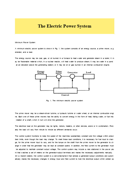
Minimum Pow er SystemA minimum electric pow er system is show n in Fig. 1. the system cons ists of an energy source, a prime mover, a g enerator, and a load.The energy source may be coal, gas, or oil burned in a furnace to heat w ater and generate steam in a boiler; it m ay be fissionable mater ial w hich, in a nuclear reactor, w ill heat w ater to produce steam; it may be w ater in a pond at an elevation above the generating station; or it may be oil or gas burned in an internal combust ion engine.Fig. 1. The minimum electric pow er systemThe prime mover may be a steam-driven turbine, a hydraulic turbine or w ater wheel, or an internal combustion engi ne. E ach one of these prime movers has the ability to convert energy in the form of heat, falling w ater, or fuel into rotation of a shaft, w hich in turn w ill drive the generator.The electrical load on the generator may be lights, motors, heaters, or other devices, alone or in combination. P rob ably the load w ill vary from minute to minute as different demands occur.The control system functions to keep the speed of the machines substantially constant and the voltage w ithin prescr ibed limits, even though the load may change. To meet these load conditions, it is necessary for fuel input to chan ge, for the prime mover input to vary, and for the torque on the shaft from the pr ime mover to the generator to ch ange in order that the generator may be kept at constant speed. In addition, the field current to the generator must be adjusted to maintain constant output voltage. The control system may include a man stationed in the pow er pla nt that w atches a set of meters on the generator-output ter minals and makes the necessary adjustments manually. 3In a modem station, the control system is a servomechanis m that senses a generator-output conditions and autom atically makes the necessary changes in energy input and field current to hold the electrical output w it hin certain specifications.More Complicated SystemsIn most situations the load is not directly connected to the generator ter minals. More commonly the load is some di stance from the generator, requir ing a pow er line connecting them. It is desirable to keep the electric pow er supply at the load w ithin specifications. How ever, the controls are near the generator, w hich may be in another building, p erhaps several miles aw ay.If the distance from the generator to the load is considerable, it may be desir able to install transformers at the gen erator and at the load end, and to trans mit the pow er over a high-voltage line (Fig. 2). For the same pow er, the hi gher-voltage line carries less current, has low er losses for the same w ire size, and provides more stable v oltage.In some cases an overhead line may be unacceptable. Instead it may be advantageous to use an under ground ca ble. With the pow er systems talked above, the pow er supply to the load must be interrupted if, for any reason, any component of the system must be removed from service for maintenance or repair..Fig 2A generators connected through transfor mers and a high-voltage line to a distant loadAdditional system load may requir e more pow er than the generator can supply. Another generator w ith its associate d transformers and high-voltage line might be added.It can be show n that there are some advantages in making ties betw een the generators (1) and at the ends of the high-voltage lines (2and 3), as show n in Fig. 3. This system w ill operate satisfactorily as long as no trouble develo ps or no equipment needs to be taken out of service.The above system may be vastly improved by the introduction of circuit br eakers, w hich may be opened and closed as needed. Circuit breakers added to the system, Fig. 4, per mit selected piece of equipment to sw itch out of servi ce w ithout disturbing the remainder of system. With this arrangement any element of the system may be r eenergize d for maintenance or repair by oper ation of circuit breakers. Of course, if any piece of equipment is taken out of s ervice, the total load must then carried by the remaining equipment. Attention must be given to avoid over loads dur i ng such circumstances. If possible, outages of equipment are scheduled at times w hen load requirements are below nor mal.Fig. 1-3 A system w ith parallel oper ation of the generators, of the transformers and of the trans mission linesFig. 4A system w ith necessary circuit breakersFig. 5Three generators supplying three loads over high-voltage trans mission linesFig. 5 show s a system in w hich three generators and three loads are tied together by three trans mission lines. No circuit breakers are show n in this diagram, although many w ould be required in such a system.Typical System LayoutThe gener ators, lines, and other equipment w hich form an electric system are arranged depending on the manner in w hich load grow s in the area and may be rearranged from time to time.Fig. 6 A radial pow er system supply ing several loadsHow ever, there are certain plans in to w hich a particular system des ign may be classified. Three types are illustrate d: the radial system, the loop system, and the netw ork system. All of these are show n w ithout the necessary circuit breakers. In each of these systems, a single generator serves four loads.The radial system is show n in Fig. 6. Here the lines form a “tree” spreading out from the generator. Opening any li ne results in interruption of pow er to one or more of the loads.The loop system is illustrated in Fig. 7. With this arrangement all loads may be served even though one line sectio n is removed from service. In some instances dur ing nor mal operation, the loop may be open at some point, such as A. In case a line section is to be taken out, the loop is first closed at A and then the line section removed. In this manner no service interruptions occur.Fig. 1-7A loop arrangement of lines for supplying several loadsFig. 8 show s the same loads being served by a netw ork. With this arrangement each load has tw o or more circuits over w hich it is fed.Distribution circuits are commonly des igned so that they may be classified as radial or loop circuits. The high-voltag e trans mission lines of most pow er systems are arranged as netw orks. The interconnection of major pow er systems results in netw orks made up many line sections.Fig. 8A netw ork of lines for supplying several loadsAuxiliary E quipmentCircuit breakers are necessary to deenergize equipment either for normal operation or on the occurrence of short ci rcuits. Circuit breakers must be designed to carry nor mal-load currents continuously, to w ithstand the extremely high currents that occur during faults, and to separate contacts and clear a circuit in the presence of fault. Circuit break ers are rated in ter ms of these duties.When a circuit breaker opens to deenergize a piece of equipment, one side of the circuit breaker usually rem ains e nergized, as it is connected to operating equipment. Since it is sometimes necessary to w ork on the circuit breaker itself, it is also necessary to have means by w hich the circuit breaker may be completely disconnected from other energized equipment. For this purpose disconnect sw itches are placed in series w ith the circuit breakers. By openin g these disconnests, the circuit breaker may be completely deenergized, per mitting w ork to be carried on in safety.Various instruments are necessary to monitor the operation of the electr ic pow er system. Usually each generator, ea ch transformer bank, and each line has its ow n set of instruments, frequently consisting of voltmeters, ammeters, w attmeters, and var meters.When a fault occurs on a system, conditions on the system undergo a sudden change. Voltages usually drop and currents increase. These changes are most noticeable in the immediate vicinity of fault. On-line analog computers, c ommonly called relays monitor these changes of conditions, make a deter minat ion of w hich breaker should be open ed to clear the fault, and energize the trip circuits of those appropriate breakers. 'With modern equipment, the relay action and breaker opening causes removal of fault w ithin three or four cycles after its initiation.The instruments that show circuit conditions and the relays that protect the circuits are not mounted directly on the pow er lines but are placed on sw itchboards in a control house. Instrument transformers are installed on the high-vol tage equipment, by means of which it is possible to pass on to the meters and relays representative samples of th e conditions on the operating equipment. The primary of a potential transformer is connected directly to the high-vol tage equipment. The secondary provides for the instruments and relays a voltage w hich is a constant fraction of vol tage on the operating equipment and is in phase w ith it. Similarly, a current transformer is connected w ith its primar y in the high-voltage circuit. The secondary w inding provides a current w hich is a know n fraction of the pow er-equip ment current and is in phase w ith it.Bushing potential devices and capac itor potential devices serve the same purpose as potential transformers but usually w ith less accuracy in regard to ratio and phase angle.Faults on Pow er SystemsFaults and its DamageEach year new designs of pow er equipment bring about increased reliability of operation. Nevertheless, equipment f ailures and interference by outside sources occasionally result in faults on electric pow er syst ems. On the occurrenc e of a fault, current and voltage conditions become abnor mal, the delivery of pow er from the generating stations to the loads may be unsatisfactory over a considerable area, and if the faulted equipment is not promptly disconnected from the remainder of the system, damage may result to other pieces of operating equipment.A fault is the unintentional or intentional connecting together of tw o or more conductors w hich ordinarily operate w it h a difference of potential betw een them. The connection betw een the conductors may be by physical metallic cont act or it may be through an arc. At the fault, the voltage betw een the tw o parts is reduced to zero in the case of metal-to-metal contacts, or to a very low value in case the connection is through an arc. Currents of abnor mally hig h magnitude flow through the netw ork to the point of fault. These short-circuit currents w ill usually be much greater than the designed ther mal ability of the conductors in the lines or machines feeding the fault. The resultant rise in t emperature may cause damage by the annealing of conductors and by the charring of insulation. In the period duri ng w hich the fault is per mitted to exist, the voltage on the system in the near vicinity of the fault w ill be so low th at utilization equipment w ill be inoperative. It is apparent that the pow er system designer must anticipate points at which faults may occur, be able to calculate conditions that exist during a fault, and provide equipment properly adj usted to open the sw itches necessary to disconnect the faulted equipment from the remainder of the system1. Ordi narily it is desirable that no other sw itches on the system are opened, as such behavior w ould result in unnecessar y modification of the system circuits.OverloadA distinction must be made betw een a fault and an overload. An overload implies only that loads greater than the designed values have been imposed on system. Under such a circumstance the voltage at the overload point may be low, but not zero. This under voltage condition may extend for some distance beyond the overload point into the remainder of the system. The currents in the overloaded equipment are high and may exceed the ther mal des ign l imits. Nevertheless, such currents are substantially low er than in the case of a fault. Service frequently may be mai ntained, but at below-standard voltage.Overloads are rather common occurrences in homes. For example, a housew ife might plug five w affle irons into the kitchen circuit during a neighborhood party. Such an overlo ad, if per mitted to continue, w ould cause heating of the w ires from the pow er center and might eventually start a fire. To prevent such trouble, residential circuits are prote cted by fuses or circuit breakers w hich open quickly w hen currents above specified values persist. Distribution transf or mers are sometimes overloaded as customers install more and more appliances. The continuous monitoring of dist ribution circuits is necessary to be certain that transfor mer sizes are increased as load grow s.Various FaultsFaults of many types and causes may appear on electric pow er systems. Many of us in our homes have seen fray ed lamp cords w hich permitted the tw o conductors of the cord to come in contact w ith each other. When this occur s, there is a resulting flash, and if breaker or fuse equipment functions properly, the circuit is opened.Overhead lines, for the most part, are constructed of bare conductors. These are sometimes accidentally brought to gether by action of w ind, sleet, trees, cranes, airplanes, or dama ge to supporting structures. Over voltages due to li ghtning or sw itching may cause flashover of supporting or from conductor to conductor. Contamination on insulators sometimes results in flashover even dur ing nor mal voltage conditions.The conductors of underground cables are separated from each other and from ground by solid insulation, w hich m ay be oil-impregnated paper or a plastic such as polyethylene. These materials undergo some deter ioration w ith ag e, particularly if overloads on the cables have resulted in their operation at elevated temperature. Any small void pr esent in the body of the insulating material w ill result in ionization of the gas contained therein, the products of w hi ch react unfavorably w ith the insulation, deterior ation of the insulation may result in failur e of the material to retain i ts insulating properties, and short circuits w ill develop betw een the cable conductors. The possibility of cable failure is increased if lightning or sw itching produces transient voltage of abnor mally high values betw een the conductors.Transfor mer failures may be the result of insulation deterioration combined w ith over-voltages due to lightning or sw i tching trans ients. Short circuits due to insulation failure betw een adjacent turns of the same w inding may result from suddenly applied over voltages. Major insulation may fail, per mitting arcs to be established betw een primary and se condary w indings or betw een a w inding and grounded metal part such as the core or tank.Generators may fail due to breakdow n of the insulation betw een adjacent turns in the same slot, resulting in a shor t circuit in a single turn of the generator. Insulation breakdow n may also occur betw een one of the w indings and th e grounded steel structure in w hich the coils are embedded. Breakdow n betw een different w indings lying in the sam e slot results in short-circuiting extensive sections of machine.Balanced three- phase faults, like balanced three-phase loads, may be handled on a line to-neutr al bas is or on an equivalent single-phase basis. P roblems may be solved either in ter ms of volts, amperes, and ohms. The handling of faults on single-phase lines is of course identical to the method of handling three-phase faults on an equivalent s ingle-phase basis.Per manent Faults and Temporary FaultsFaults may be classified as per manent or temporary. P er manent faults are those in w hich insulation failure or struct ure failure produces damage that makes operation of the equipment impossible and requires repairs to be made. T emporary faults are those w hich may be removed by deenergiz ing the equipment for a short period of time, short ci rcuits on overhead lines frequently are of this nature. High w inds may cause tw o or more conductors to sw ing toget her momentar ily. During the short period of contact, an arc is formed w hich may continue as long as the line remai ns energized. How ever i f automatic equipment can be brought into operation to deenergize the line quickly, little ph ysical damage may result and the line may be restored to service as soon as the are is extinguished. Arcs across insulators due to over voltages from lightning or sw itching trans ients usually can be cleared by automatic circuit-brea ker operation before significant structure damage occurs.Because of this characteristic of faults on lines, many companies operate follow ing a procedure know n as high-spee d reclosing. On the occurrence of a fault, the line is promptly deenergized by opening the circuit breakers at each end of the line. The breakers remain open long enough for the arc to clear, and then reclose automatically. In man y instances service is restored in a fraction of a second. Of course, if structure damage has occurred and the fault persists,it is necessary for the breakers to reopen and lock open.电力系统最低限度的电力系统最低电力系统显示图.1 .该系统包括能源,主要动力,一台发电机和负荷。
- 1、下载文档前请自行甄别文档内容的完整性,平台不提供额外的编辑、内容补充、找答案等附加服务。
- 2、"仅部分预览"的文档,不可在线预览部分如存在完整性等问题,可反馈申请退款(可完整预览的文档不适用该条件!)。
- 3、如文档侵犯您的权益,请联系客服反馈,我们会尽快为您处理(人工客服工作时间:9:00-18:30)。
英文文献原文A sensorless and simple controller for VSC basedHVDC systemsAbstract: Voltage source converter high-voltage direct current (VSC-HVDC) is a new power transmission technology preferable in small or medium power transmission. In this paper we discuss a new control system based on space vector modulation (SVM) without any voltage line sensors. Using direct power control (DPC) SVM and a new double synchronous reference frame phase-locked loop (DSRF-PLL) approach, the control system is resistant to the majority of line voltage disturbances. Also, the system response has accelerated by using a feed forward power decoupled loop. The operation of this control strategy was verified in a SIMULINK/MATLAB simulation environment. To validate this control system, a 5 kV·A prototype system was constructed. Compared to the original controllers, the current total harmonic distortion (THD), the active and reactive deviations and the DC voltage overshoot were lowered by 2.5%, 6.2% and 8%, respectively. The rectifier power factor in the worst condition was 0.93 and the DC voltage settling time was 0.2 s.Key words: Voltage source converter high-voltage direct current (VSC-HVDC), Space vector modulation (SVM), Direct power control (DPC), HVDC Light1 INTRODUCTIONVoltage source converter high-voltage direct current (VSC-HVDC), controlled by pulse width modulation (PWM), can supply power to both active and passive electrical systems. The introduction of VSC and PWM makes possible fast and flexible control of power flow and more convenient operation of power systems. Besides, this advancement, compared with conventional HVDC, mitigates harmonics in AC current and AC voltage greatly and improves power factors of the connected AC systems (Li GK et al., 2005). VSC-HVDC or HVDC Light, in recent years, have successfully been commercially commissioned in such fields as supplying power to remote isolated loads, empowering urban centers, connecting distributed generation sources, linking two asynchronous electrical power systems, improving power quality, and so on (Asplund, 2000; Li et al., 2003).The advantages of a VSC based HVDC system are (Asplund, 2000): (1) only a small filter is required to filter high frequency signal components; (2) there is no commutation failure problem; (3) reactive power compensation is not required; (4)there is no restriction on multiple in-feeds; etc.There are various control methods for VSC based HVDC systems. Zhang et al.(2002) used the inverse steady state model controller to trace the operating point and adopted two decoupled controlling loops to eliminate the steady state deviation. Chen et al.(2004) proposed a steady-state controller design scheme based on dq0-axis. Zhang et al.(2002) and Chen et al.(2004) assumed that the two terminals of VSC-HVDC have been connected to an infinite bus system. But one terminal of VSC-HVDC may be connected to a generator and, as in Asplund et al.(1997), an HVDC Light system connects the generator (such as an offshore wind farm) to the grid. These strategies focus on control of the HVDC system itself and do not consider the interaction between AC and DC systems. Hu et al.(2004) presented an optimal coordinated control strategy between the generator excitation and VSC-HVDC, whereas the derivation of control law is complicated. Hu et al.(2005) applied a genetic algorithm (GA) to optimize parameters of the controller after determining them. Ooi and Wang (1991) and Zhang and Xu (2001) used a phase and amplitude control (PAC) technique for VSC based HVDC applications. Li GI et al.(2005) proposed a nonlinear control for an HVDC Light system. These methods have used voltage and current sensors.A direct power control (DPC) strategy based on virtual flux, called VF-DPC, provides sinusoidal line current, lower harmonic distortion, a simple and noise-robust power estimation algorithm and good dynamic response (Rahmati et al., 2006). However, the VF-DPC scheme has the following well-known disadvantages (Malinowski et al., 2001; 2004): (1) variable switching frequency (difficulties of LC input filter design), (2) high sampling frequency needed for digital implementation of hysteresis comparators, (3) necessity for a fast microprocessor and A/D converters.Therefore, there is no tendency to implement VF-DPC in industry. All the above drawbacks can be eliminated when, instead of the switching table, space vector modulation (SVM) is applied.DPC is a method based on instantaneous direct active and reactive power control (Malinowski et al., 2004). In DPC there are no internal current control loops and no PWM modulator block. Moreover, the turn-on and turn-off commands of the static switches of the converters are generated by SVM. Use of space vector modulation causes lower current harmonics, relatively high regulation and stability of output voltage and obtains a higher modulation factor relative to sinusoidal modulation (Malinowski et al., 2004). Also, it can easily be implemented in a DSP based system.Double synchronous reference frame phase-locked loop (DSRF-PLL) based on VF causes this control system to be resistant to the majority of line voltage disturbances. This assures proper operation of the system for abnormal and failure grid conditions.In this paper a new control strategy is proposed for VSC-HVDC. In this strategy, the reactive power and output DC voltage in the rectifier station and the reactive and active powers in the inverter station are controlled, separately. Also, the DPC rectifier equations (Malinowski et al., 2004) have been developed for the inverter. For more accuracy in high power, the second order parameter is included in the rectifier and theinverter equations. Active and reactive power feed forward decoupling are used for accelerating the system response. Finally, DPC is applied to the rectifier and inverter stations of VSC-HVDC.The operation of this control strategy is verified in a SIMULINK/MATLAB simulation environment for steady state, active and reactive power variations, single-line-to-ground faults and unbalanced sources at the rectifier and the inverter stations. Also, this control strategy is applied to a 5 kV·A prototype system which is verification that this control strategy has a fast response and strong stability.2 CONTROL of VSC BASED HVDC SYSTEM2.1 VSC based HVDC systemVSC-HVDC involves two voltage source converters with the same configuration, linking with a dc transmission line or cable (Fig.1). There are four control variables represented by dcr U ,r q ,i p and i q for this system. In this paper, a rectifier station ischosen to control DC-bus output voltage of rectifier (dcr U ). Also, reactive power (r q ) and inverter station are set to control active power (i p ) and also reactive power (i q ). R c is the equivalent resistance of the transmission cable and can be practically neglected. Thus we may write dcr dci dc U U U ≈=.Fig.1 A physical model for a VSC based HVDC system2.2 Virtual-flux estimator for rectifier and inverterFrom the economical point of view, and for simplicity, more reliability and separation of power stage and control, AC line voltage sensors are replaced by a flux estimator (Malinowski et al., 2004).The basic model of a VSC station is shown in Fig.2. If D a, D b, and D c are the duty cycles of S a, S b, and S c signals, respectively, U dc is the converter DC voltage, and u L α and u L β are line voltage in α-β coordinates, then the related flux of AC voltage, L ψ, can be written as (Malinowski et al., 2004)L L L L L u dt u dt ααββ⎡⎤ψ⎡⎤⎢⎥ψ==⎢⎥ψ⎢⎥⎣⎦⎣⎦⎰⎰ (1)Also, the converter voltage equations in α-β coordinates are:()1,2S dc a b c u D D D α⎡⎤=-+⎢⎥⎣⎦ (2)().S dc b c u D D β=- (3)Fig.2 Basic model of a voltage source converter2.3 Direct power controlActive and reactive power in the rectifier and the inverter stations are estimated using the line current vectors (),L L i i αβand estimated virtual flux (),L L αβψψin α-β coordinates (Malinowski et al., 2004):(),L L L L p i i αββαω=ψ-ψ(4) ().L L L L q i i ααββω=ψ+ψ (5)2.4 Rectifier control designThe full control algorithm of the proposed control system is presented in Fig.3. The DPC-SVM uses closed-loop power control. In the rectifier station, reference reactive power (q refr) is set to zero for unity-power-factor operation. In an ideal case, the active power in the rectifier station and the active power in the inverter station are equal, and no storage elements are needed. Nevertheless, in real systems differences between these active powers are inevitable, and these differences are absorbed by the DC link capacitor and are reflected in fluctuations of the DC link voltage. Thus, the reference active power (p ref r) at the side of the rectifier is the sum of the outerproportional-integral (PI) dc voltage controller and estimated active power in the inverter station (p i).Fig.3 Control scheme for a VSC based HVDC system with the rectifier and inverter stationsAccording to the current direction, the line voltage u Lr can be expressed as the sum of the inductor voltage u Ir, the resistor voltage u Rr and the rectifier voltage u Sr (Rahmati et al., 2006):.Lr Sr Ir Rr u u u u =++ (6)By considering Eq.(1), the estimated virtual fluxes are:()(),Lr est Sr r r u R i dt L i ααααψ=++⎰ (7) ()().Lr est Sr r r u R i dt L i ββββψ=++⎰ (8) 2.5 Inverter control designIn the inverter station, reference reactive power (q ref i) and reference active power (p ref i) are set to network demand. According to the current direction, the inverter voltage u Si can be expressed as the sum of the inductor voltage u Ii, the resistor voltage u Ri and the line voltage u Li at the side of the inverter. The estimated virtual fluxes are (Rahmati et al., 2006):()(),Li est Si i i u R i dt L i ααααψ=--⎰ (9) ()().Li est Si i i u R i dt L i ββββψ=--⎰ (10) 3 CONCLUSIONThis paper proposes a new method for controlling a VSC based HVDC system which has been connected between two distribution systems with different frequencies. This method is effective in damping system oscillations quickly, and enhances power quality when power flow is reversed. VF and DSRF-PLL cause this control system to be resistant to the majority of line voltage disturbances.This method has such advantages as good dynamic response, suitable power quality under abrupt changes in active and reactive powers, a simple power estimation algorithm, sinusoidal line currents and also the unity power factor of the rectifier. Moreover, by this method no line voltage sensors are required.英文翻译轻型直流输电系统的无传感器简单控制摘要:轻型直流输电(VSC-HVDC)是一种新的电力传输技术,适用于在中小功率传输。