医用数字胶片打印机操作手册
edx-720操作说明书

选项
设置要求
分析
选择
单位
μm
处理-计算
固定
固定
0.0000
输入
Fix
38、点击“Cr”,出现如图 37 所 示窗口按照下表中的要求设置好 各项参数,设置好后点击“应用” 按钮,再分别点击 Ni、Zn、Cd、 Pb,重复设置工作。
操作流程 E 关机
1 结束
显示界面
图 16 2 5
3 4
操作说明
43、如果需要测试其它样品,重 复步骤 18~42。
44、所有测试完毕后,关闭除了 “EDX-主程序”外的所有窗口。 点击“EDX-主程序”窗口上的“维 护”,出现如图 4 窗口。点击“仪 器设置…”按钮,出现如图 2 窗 口。点击“启动/关闭”按钮,关 闭 X 光管。
打印项目 所有
谱线列表
定量结果
计算单位 所有
%
横向
方向
所有 多重通道显
示
样品形状 所有
块状
组成形式
镀层 氧化物
金属 氧化物
参考系统 组别
所有
sysmetal
操作流程 A
保存工作组
显示界面
图 21 图 22 图 23
操作说明 7、按第六步设置好后,点击“测 试通道”里的“元素周期表”按 钮,显示出如图 21 所示窗口。
D
显示界面 图 29
图 30 图 31
操作说明 24、在“组别名称”里填上工作 组的名称,例如“FP 法测试”, 在“说明”栏里填写上需要进行 说明的信息。
25、点击“确认”按钮,出现如 图 27 所示窗口。
26、按第 6 步的参数要求来设置, 但是“样品形态”这一栏选择“薄 膜”,出现如图 28 所示窗口。
医用数字胶片打印机操作手册
医用数字胶片打印机操作手册医用数字胶片打印机操作手册1.介绍1.1 操作手册目的本操作手册旨在提供对医用数字胶片打印机的详细操作指南,帮助用户正确使用该设备,以确保照片打印的质量和安全性。
1.2 读者对象本操作手册适用于所有使用医用数字胶片打印机的操作人员。
1.3 所需背景知识为了更好地理解和操作本打印机,操作人员应具备以下背景知识:- 对数字胶片打印技术的基本了解- 对医用影像的处理和存储有一定的了解2.设备概述2.1 设备外观- 此处可附上设备外观的图片或描述2.2 主要功能2.2.1 照片打印2.2.2 打印质量调节2.2.3 打印速度调节2.2.4 打印胶片格式选择3.准备工作3.1 设备安装3.1.1 设备放置- 为了保证设备的稳定性和正常工作,请将设备放置在平整牢固的台面上。
3.1.2 电源连接- 将设备的电源线连接到电源插座上,并确保电源连接稳固。
3.2 胶片准备3.2.1 胶片检查- 在使用胶片前,请检查胶片的完整性和质量。
3.2.2 胶片放置- 将胶片放置在设备指定的胶片仓中,并确保胶片放置正确。
4.操作步骤4.1 打印照片4.1.1 打开设备电源- 按下电源按钮,等待设备启动完成。
4.1.2 选择照片- 使用设备配套的软件或界面,选择要打印的照片。
4.1.3 调节打印质量- 根据需要调节打印质量参数,如亮度、对比度等。
4.1.4 调节打印速度- 根据需要调节打印速度参数,以满足不同的打印需求。
4.1.5 打印照片- 确认设置无误后,打印按钮,开始打印照片。
5.故障排除5.1 无法打开设备电源- 检查电源线是否正常连接,检查电源插座是否工作正常。
5.2 打印质量不佳- 检查胶片质量、打印质量参数设置是否正确,如需要可更换胶片或重新调整参数。
5.3 打印速度过慢或过快- 检查打印速度参数设置是否正确,如需要可调整打印速度参数。
附件:附件1:医用数字胶片打印机设备外观示意图附件2:医用数字胶片打印机相关法律法规法律名词及注释:1.医用数字胶片打印机:指用于医疗影像打印的数字化设备。
carestream胶片打印机使用说明

carestream胶片打印机使用说明
一、胶版打印机的启动
胶片打印机的正常运行,系统启动必须严格按照以下顺序进行操作。
1、打开X光机的配电柜电源总开关。
2、接通接线板电源,接通X光机X线控制电源,接通电脑主机电源。
3,开启文字报告答应机(激光打印机或者喷墨打印机)。
4、开启胶片打印机。
5、DRX光机系统开始正常工作。
二、关闭DRX光机系统
1、退出技术工作站软件
关闭技术工作站,让计算机自动关闭。
2、退出医生工作站软件
关闭医生工作站,让计算机自动关闭。
3、退出病例中心软件,关闭病例中心工作站,让计算机自动关闭。
4、关闭报告打印机
按照文字报告打印机(激光打印机或者喷墨打印机)操作要求关闭打印机。
5、关闭胶片打印机
按照胶片打印机操作要求关闭胶片打印机。
6、关闭电源
1、关闭X线高压电源。
2、关闭控制柜电源。
3、关闭计算机配电接线板电源。
4、关闭配电柜电源总开关。
医用数字胶片打印机操作手册
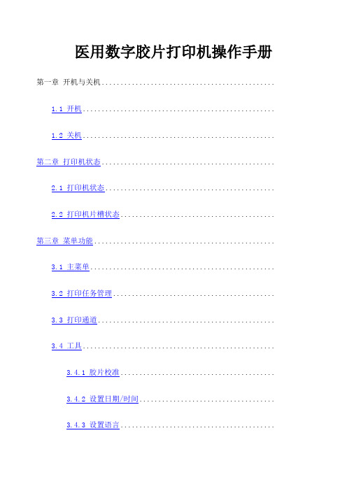
医用数字胶片打印机操作手册第一章开机与关机..............................................1.1 开机...................................................1.2 关机................................................... 第二章打印机状态..............................................2.1 打印机状态.............................................2.2 打印机片槽状态......................................... 第三章菜单功能................................................3.1 主菜单.................................................3.2 打印任务管理...........................................3.3 打印通道...............................................3.4 工具...................................................3.4.1 胶片校准.........................................3.4.2 设置日期/时间....................................3.4.3 设置语言.........................................3.4.4 片盒设置.........................................3.5 测试打印...............................................3.6 网络设置...............................................第一章开机与关机1.1 开机按启动打印机。
富士医疗干式激光相机4000说明书
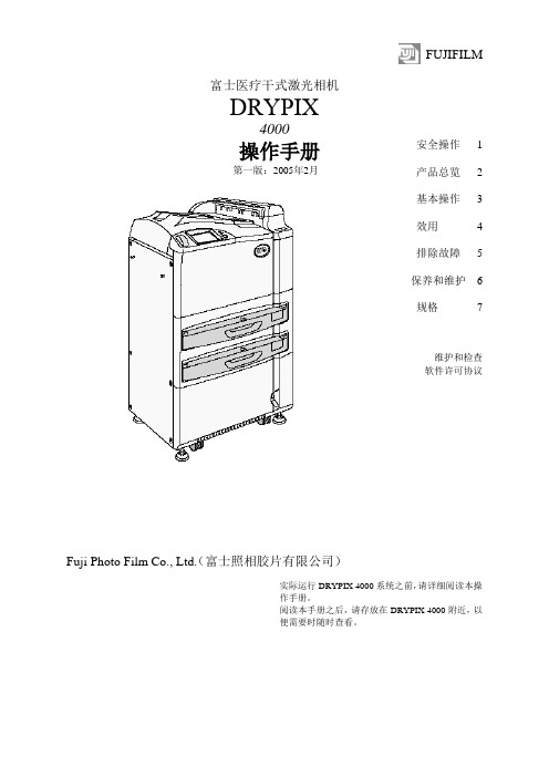
FUJIFILM富士医疗干式激光相机DRYPIX4000操作手册第一版:2005年2月Fuji Photo Film Co., Ltd.(富士照相胶片有限公司)安全操作 1 产品总览 2 基本操作 3 效用 4 排除故障 5 保养和维护 6 规格7维护和检查软件许可协议实际运行DRYPIX 4000系统之前,请详细阅读本操作手册。
阅读本手册之后,请存放在DRYPIX 4000附近,以便需要时随时查看。
ii DRYPIX 4000操作手册897N0218 2005年2月介绍介绍非常感谢您购买富士医疗干式激光相机DRYPIX 4000。
富士医疗干式激光相机DRYPIX 4000是将数字图像数据以所选格式打印至专用胶片的设备,数字图像数据来自FCR图像阅读器或CT、MRI和其它成像设备,经DICOM网络传送。
本DRYPIX 4000操作手册提供操作方法和注意事项的详细解释,以便促进正确理解功能并且能够更有效地使用。
我们要求首次使用的用户在实际应用DRYPIX 4000之前,详细阅读本手册。
阅读之后,请将其存放在DRYPIX 4000附近,便于使用,以保证在最佳状态下使用该设备。
小心The DRYPIX 4000使用Vx Works。
Vx Works的版权属于Wind River Systems, Inc。
版权所有<禁止重新打印和/或复制部分或全部本手册。
>版权所有。
2005 富士照相胶片有限公司。
DRYPIX 4000操作手册897N0218 2005年2月iiiiv DRYPIX 4000操作手册897N0218 2005年2月内容浏览内容浏览第1章安全操作本章介绍我们希望您注意的安全操作本设备所需了解的警告(Warning)和小心(Caution)。
第2章产品总览本章介绍该设备的总览和主要特性。
第3章基本操作本章描述常规操作程序,包括如何启动/关闭该设备以及如何更换胶片盒。
第4章效用本章解释如何校准胶片输出密度和设置Economy Mode(经济模式)。
全镜DR150DR字型胶带打印机用户指南说明书

Fasteners & Tools Needed8621- Steel rivet8709-ScrewYou will need these tools to assemble the accessories into locker.Rivet gun.Drill with #3 Philips bitFlat blade and Phillips head screwdrivers.Table of ContentsStep 1…………...………..Security Box Installation Step 2…………..….…………..L Shelf Installation Step 3....................Inner Compartment Installation Step 4……………...…Center Partition Installation Step 5……………...………...Half Shelf Installation Step 6…………..………..….6” Drawer Installation Step 7……….12” Side by Side Drawer Installation Step 8………………………Footlocker Installation Step 9………..Metal and Wooden Seat Installation Step 10……………….....Channel Base Installation Step 11......……....…..Document Sleeve Installation Step 12…......……………..…Cell Tray Installation Step 13 ………………...……Coat Rod Installation STEP 1 – Assemble and install optional security box.Note security boxes can go on right or left side of locker shelf. Attachment of divider is opposite of security box placement.Parts:Step-1A Security box assembly and Installation Assemble the security box side to the frame using two rivets as shown. Note if locker sides are perforated and you need to hide security box contents then an additional side is required. Install this extra side on the opposite side facing the same way as the one in the image below.Optional side cover for hiding security box contents when locker sides are perforated. 1B Install security box by sliding it onto the shelf in the appropriate position and secure it using four rivets as shown.1C Install top clip to locker top rail and to doorframe using screw and rivets as shown.1D Install screw through security box division and into the locker top back rail as shown. Note locker back is invisible to show clear view.If optional side cover is needed install as shown below.Installing an L shelf.Step-2A install L shelf support rail at the proper height (12 inches down from shelf) using one screw into each vertical upright. 2B Place L shelf on top of support rail and locate on shelf above and insert four rivets to hold in proper location.Repeat this process again for additional shelves.Installation of Inner compartment:Step-3A Place plastic guide hubs into the inner compartment door holding it in place at the bottom until it is located in the correct position on the L or half shelf. 3B Insert the locking pins into the hubs in the top and bottom locking the door in place. 3C Install doorknob with screw on the backside of the door. 3D Install lock by placing it from the backside with the screws entering from the front in the provided holes and install nuts on each screw.To hide contents of, the inner compartment because the side is perforated install side cover. Install as shown using two rivets on the bottom and two screws on the top.Install center partitionStep-4A If full width coat rod is installed remove one side to allow coat rod to go through center partition hole. 4B Place center partition in correct location under the shelf and install the required rivets or nut and bolt. 4C Align bottom of partition in correct location on lower shelf or bottom. If a lower shelf is used, install with rivets or nut and bolt. If no lower shelf is used then install with self-tapping screws. (There are no guide holes on locker bottoms.)Installing a half shelf.Step-5A Install half shelf support rail at the proper height location using one screw into each vertical upright. 5B Place half shelf on top of support rail, locate on shelf above, and insert four rivets to hold in proper location.Installing 6” drawersStep-6A Install shelf at desired location for first drawer. 6B install mounting rails for drawer using the 8709 screws provided. 6C Install drawer guide rails using two rivets attached to mounting rails. 6D Install plastic glide rails to drawer guide rails using the provided screws. Then insert drawer onto the glide rails.6E Install mounting rails for next drawer using the 8709 screws provided. 6F Install drawer guide rails using two rivets attached to mounting rails. 6G Install plastic glide rails to drawer guide rails using the provided screws. Then insert drawer onto the glide rails.Installation of side-by-side drawers7B Install shelf on support rails using four rivets. Step-7A Install support rails for shelf at 13.9” upmeasured from the outside bottom. Install shelf onsupport rails using four rivets. Next install mountingrails for drawer using the 8709 screws provided.Next install drawer guide rails using two rivetsattached to mounting rails. Install plastic glide railsto drawer guide rails using the provided screws.Next insert drawer onto the glide rails.7C Install divider using rivets and screws. (Note it iscritical to get this in the correct location for proper fitof side-by-side drawers.)7D Install mounting rail for drawer using the 8709 screws provided. 7E Install drawer guide rails using two rivets attached to mounting rail and divider.7F Install plastic glide rails to drawer guide rails using the provided screws. Next insert drawer onto the glide rails.7G Install guide rail to divider using rivets.7H Install divider using rivets and screws. (Note it iscritical to get this in the correct location for proper fitof side-by-side drawers.)7I Install mounting rail for drawer using the 8709screws provided7J Install drawer guide rails using two rivets attached to mounting rail and divider.7K Install plastic glide rails to drawer guide rails using the provided screws. Then insert drawer onto the glide rails.STEP 4- Install Footlocker4A- Install the side mounting rails at the properheight locations using one screw in each corner. Railheight for footlocker is 13.9 inches from the outsidebottom corner to the top of the rail. Two mountingrails required one on each side.4B- Now install the footlocker front panel byinserting it behind the vertical corner posts and intothe slots of the horizontal side rails and attach usingfour rivets.4C- Next install the seat assembly using four rivets into the horizontal rails at the proper locations.4D- Now install the rubber bumpers on the seat and at proper height on the vertical posts.Metal or Wood Seat Installation9A- Install the side mounting rails at the properheight locations using one screw in each corner. Railheight for 18-inch high seat is 16.9 inches from theoutside bottom corner to the top of the rail. Twomounting rails required one on each side.9B- Rivet seat to mounting rails in each corner asshown. For wooden seat install with lag bolts in eachcorner.For wooden seat, add the lag bolts as shown.Channel Base Installation10A- Install channel base by aligning in proper location and adding four bolts one in each corner.Document Sleeve Installation11A- Install document sleeve by aligning in desired location and orientation and install with four rivets as shown.Cell Tray Installation12A- Install cell tray by placing in desired position and rivet using two rivets as shown.Coat hooks and Coat Rod Installation13A Install 8717 coat hooks, and coat rod using two rivets per hook as shown. Note it is necessary to put coat rod in place while installing last coat hook.。
R200操作步骤

Iconos R200 简易操作手册开机:按下发生器控制台上的开机按钮关机:按下发生器控制台上的关机按钮DFR模式:1、输入病人信息(Last Name, First Name, Patient ID, Birth Date等黑体字项为必填项),点击“OK”进入“Examination”界面开始检查2、器官程序选择和确认。
在发生器控制台上选择与当前检查部位相匹配的器官程序3、透视定位(Examination界面)。
移动球管或检查床,使要查看的部位到达屏幕的中心位置。
4、检查操作(Examination界面)。
根据不同检查和部位的要求进行透视、点片操作,直到所有的检查内容完成。
5、图像后处理(Postprocessing界面)。
加入左右标签,标记要打印或发送的图像,调整亮度、对比度、H或F等6、打印胶片(Documentation界面)。
选择好激光相机、胶片格式、分格方式,进行预览,满意后点击打印按钮即可7、图像发送((Documentation界面,有PACS工作站的情况下)。
选择好服务器名称,点击发送按钮即可8、进入下一个病人的检查Spotfilm模式1、使用Emergency(急诊)模式进入Examination(检查)界面2、放胶片。
把合适的胶片放到检查床下的胶片架中3、器官程序选择。
从发生器控制台选择模式为Spotfilm模式,并选择好相应的器官程序。
4、胶片分格检查。
根据需要,按亮相应分格按钮灯。
5、滤线栅移如或移出。
根据需要,请检查虑线栅的情况,并根据需要移入或移出。
6、透视定位,此时要注意感兴趣区域的位置,如不符合要求,一定要改为正确的区域。
透视时间要求不少于2秒钟7、按亮控制台上的“Bucky Mode”按钮8、曝光Free Exposure(自由曝光)模式1、调整球管。
旋转球管,使准直器对准检查部位2、放胶片。
把合适的胶片放到检查部位下面3、手动设置好曝光条件。
4、曝光Bucky Wall Stand(胸片架)模式1、调整球管。
富士DRYPIX2000手册
介绍该操作指南使用在下列软件中,产品由主要部件、内存板、软盘、胶片供给盒和其他选件组成。
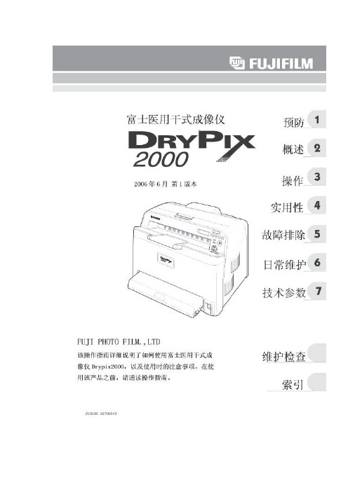
DRYPIX2000打印软件V1.0富士医用干式成像仪DRYPIX2000是一种打印机,其是通过FCR图片识别器,CT或MRI扫描仪上的DICOM网络对数字图片进行打印。
为了您更好的使用并了解DRYPIX2000的功能和性质,“DRYPIX2000使用说明书”对DRYPIX进行了详细的说明,其中也包括重要的安全信息.注意事项:1.严禁在未经授权的情况下,对该使用指南进行修改或复制.2.在没有提前通知的情况下,操作指南的相关内容不得进行更改.3.对于非Fuji Photo公司或其承包商对您产品进行安装,移动,维护或维护等行为对您的产品造成毁坏的话,Fuji Photo Film公司不承担任何责任.4.Fuji Photo Film有限公司对于第三方的零部件(非Fuji公司所发售的零部件)对您所造成的一切损失与不负任何责任.5.对于您使用未经Fuji Photo Film公司认证的零部件对产品进行更换,维修而造成设备的损坏,Fuji Photo Film公司不承担任何责任.6.对于您未仔细阅读该操作指南而在使用时设备发生损坏等现象,Fuji Photo Film公司不承担任何责任.7.对于您未能遵循操作指南所规定的环境条件,温度而造成设备的损坏,Fuji PhotoFilm公司不承担任何责任。
8.对于自然灾难如火灾,地震,洪水,闪电等对您所造成的损坏,Fuji Photo Flim公司不承担任何责任.注意:Rx仅在美国适用(联邦法律禁止医师或相关职业人员销售此设备)该产品使用VxWorksVxWorks的版权归Wind River公司所有.严禁在未经允许的情况下复制CD-ROM文件.商标:是Fuji Photo Film公司的注册商标.版权所有.DRYPIX2000操作指南章节描述第一章预防 1 该章节详细介绍了在使用DRYPIX2000时应注意的事项.第二章概述 2 该章节描述了DRYPIX功能和特点以及各个部件的名称和功能.第三章操作 3 该章节描述了设备的启动,关闭以及图片的打印.第四章实用性 4 该章节描述了在使用DRYPIX2000时,周围环境的设置.第五章故障排除 5 该章节描述了当操作设备时,出现故障时的解决方法。
- 1、下载文档前请自行甄别文档内容的完整性,平台不提供额外的编辑、内容补充、找答案等附加服务。
- 2、"仅部分预览"的文档,不可在线预览部分如存在完整性等问题,可反馈申请退款(可完整预览的文档不适用该条件!)。
- 3、如文档侵犯您的权益,请联系客服反馈,我们会尽快为您处理(人工客服工作时间:9:00-18:30)。
医用数字胶片打印机操作手册
第一章开机与关机 (2)
1.1 开机 (2)
1.2 关机 (2)
第二章打印机状态 (3)
2.1 打印机状态 (3)
2.2 打印机片槽状态 (4)
第三章菜单功能 (5)
3.1 主菜单 (5)
3.2 打印任务管理 (6)
3.3 打印通道 (7)
3.4 工具 (8)
3.4.1 胶片校准 (9)
3.4.2 设置日期/时间 (11)
3.4.3 设置语言 (12)
3.4.4 片盒设置 (13)
3.5 测试打印 (14)
3.6 网络设置 (16)
第一章开机与关机
1.1 开机
按启动打印机。
1.2 关机
按进入<关机>页面。
●按选择“关机”“重新启动”。
●按确定执行。
●按退出<关机>页面。
第二章打印机状态
2 1
3
4
2.1 打印机状态
2.2 打印机片槽状态
第三章菜单功能
3.1 主菜单
在<状态>页面,按进入<主菜单>页面。
●按选择“打印任务管理”“打印通道”“工具”“测试打印”“网
络设置”“关机”。
●按进入下一级菜单。
●按退出<主菜单>页面。
3.2 打印任务管理
●按选择要操作的打印任务。
●按选择“删除”“删除所有”“修改尺寸”。
●按确定执行。
●按返回<主菜单>页面。
操作功能
删除删除选择的打印任务。
删除所有删除所有打印任务。
修改尺寸修改选择的打印任务的打印尺寸。
按键,在当前使用的胶片尺寸间选择。
3.3 打印通道
按选择打印通道。
名称说明Name 打印通道名称。
Channel Size 打印通道支持接收的打印尺寸。
Film Size 打印通道实际使用的胶片尺寸。
AE 打印通道特定支持的AE。
IP 打印通道特定支持的IP。
3.4 工具
●按选择“胶片校准”“设置日期/时间”“语言”。
●按进入下一级菜单。
●按进入上一级菜单。
3.4.1 胶片校准
选择要校准的片盒。
●按选择校正片盒。
●按进入下一级菜单。
●按进入上一级菜单。
进行校准。
●按校准。
●按取消。
3.4.2 设置日期/时间
●按选择“年”“月”“日”“时”“分”“秒”。
●按修改。
●按确定执行。
●按进入上一级菜单。
3.4.3 设置语言
●按选择“简体中文”“English”。
●按确定执行,重启打印机后生效。
●按进入上一级菜单。
3.4.4 片盒设置
●按选择要修改的项。
●按修改。
●按确定修改。
●按进入上一级菜单。
3.5 测试打印
选择要打印的尺寸。
●按选择打印尺寸。
●按进入下一级菜单。
●按进入上一级菜单。
选择要打印的测试片。
●按选择测试片。
●按进入打印。
●按进入上一级菜单。
3.6 网络设置
●按选择操作的项。
●按修改“IP地址”“子网掩码”“网关”“端口”的值。
●选择“修改AE”,按修改“AE_Title”的值。
●选择“重启服务”,按确定执行。
●按进入上一级菜单。