SMC PF3W7-中文说明书(完整版)
smc-数字式压力开关-使用说明书

文件No.PS※※-OMS0006CN-G数字式压力开关ZSE20(F)ISE20安全注意事项2型式表示・型号体系8产品各部位名称及功能10用语说明11安装·设置14设置方法14配管方法16配线方法18设定概要[测量模式] 20 压力设定21 3步设定模式22 简易设定模式24功能选择模式26功能选择模式说明26出厂设定26 F0 单位切换功能28 F1 OUT1的设定29 F3 数字滤波器的设定32 F4 自动预设功能的设定33 F6 显示值微调的设定35 F10 子画面的设定36 F11 显示分辨率的设定41 F80 省电模式的设定42 F81 密码输入的设定43 F82 线名输入的设定45 F90 全功能的设定46 F98 输出确认48 F99 恢复出厂设置49其他设定50维护54忘记密码的场合54故障一览表55规格62规格表62外形尺寸图64安全注意事项此处所示的注意事项是为了确保您能安全正确地使用本产品,预先防止对您和他人造成危害和伤害而制定的。
这些注意事项,按照危害和损伤的大小及紧急程度分为「注意」「警告」「危险」三个等级。
无论哪个等级都是与安全相关的重要内容,所以除了遵守国际规格(ISO/IEC)、日本工业规格(JIS)*1)以及其他安全法规*2)外,这些内容也请务必遵守。*1) ISO 4414: Pneumatic fluid power -- General rules relating to systemsISO 4413: Hydraulic fluid power -- General rules relating to systemsIEC 60204-1: Safety of machinery -- Electrical equipment of machines (Part 1: General requirements)ISO 10218: Manipulating industrial robots-SafetyJIS B 8370: 空气压系统通则JIS B 8361: 油压系统通则JIS B 9960-1: 机械类的安全性-机械的电气装置(第1部:一般要求事项)JIS B 8433: 产业用操作机器人-安全性等*2) 劳动安全卫生法等注意误操作时,有人员受伤的风险以及物品破损的风险。警告误操作时,有人员受到重大伤害甚至死亡的风险。
SMC压力表说明书(标准版)
SMC压力表说明书(标准版)尊敬的用户:感谢您选择本公司的压力表产品。
在使用本压力表前,请仔细阅读本说明书,以便正确地使用和维护压力表。
一、产品简介本压力表采用高精度传感器和先进的微处理器技术,具有测量准确、稳定可靠、操作简便等特点,适用于各种工业领域中的压力测量。
二、产品型号与规格1. 产品型号:SMC-YZ012. 量程范围:0-100MPa3. 精度等级:0.5级4. 工作电源:DC 3.6V5. 显示方式:LCD液晶显示6. 输出信号:RS485三、操作说明1. 开机:将压力表的电源开关拨至“ON”位置,等待约3秒后,压力表将自动开机。
2. 关机:将压力表的电源开关拨至“OFF”位置,等待约3秒后,压力表将自动关机。
3. 测量:将压力表的测量接口连接到待测压力源,压力表将自动测量并显示压力值。
4. 设置:通过按压压力表上的“SET”键,可进入参数设置模式。
在设置模式下,可通过按压“UP”和“DOWN”键调整参数值,然后按压“SET”键确认。
四、维护与保养1. 使用过程中,请勿让压力表受到撞击、摔打等强烈冲击,以免损坏压力表。
2. 请定期检查压力表的连接线、接头等部件,如有损坏或磨损,请及时更换。
3. 请定期清洁压力表的外壳和显示屏幕,保持压力表的清洁。
4. 请定期检查压力表的电池电量,当电池电量低于30%时,请及时更换电池。
五、注意事项1. 本压力表仅适用于测量压力,严禁用于其他目的。
2. 在测量过程中,请勿让压力表过载,以免损坏压力表。
3. 请勿擅自拆卸、改装压力表,如有需要,请与本公司联系。
4. 请妥善保管本说明书,以备日后参考。
六、附件1. 压力表x 12. 测量连接线x 13. 说明书x 1感谢您对本公司的支持,祝您使用愉快!如有任何问题,请随时与本公司联系。
联系电话:联系邮箱:公司网址:。
SMC PF2A3 PF2W3 PF2D3 流量监测仪操作手册说明书
Flow MonitorOperation ManualPF2A3/PF2W3/PF2D3Installation•Never mount the product in a location that will be used as a foothold.Thank you for purchasing an SMC PF2A3/PF2W3/PF2D3Series Flow Monitor.Please read this manual carefully before operating the product and make sure you understand its capabilities and limitations.Please keep this manual handy for future reference.To obtain more detailed information about operating this product, please refer to the SMC website (URL ) or contact SMC directly.These safety instructions are intended to prevent hazardous situations and/or equipment damage.These instructions indicate the level of potential hazard with the labels of"Caution", "Warning" or "Danger". They are all important notes for safety and must be followed in addition to International standards (ISO/IEC) and other safety regulations.OperatorSafety InstructionsMaintenanceHow to reset the product after a power cut or forcible de-energizing The setting of the product will be retained as it was before a power cut or de-energizing.The output condition is also basically recovered to that before a power cut or de-energizing, but may change depending on the operating environment.Therefore, check the safety of the whole installation before operating the product.Mounting and InstallationInstallingRemoving the panel mount adapter•Remove the panel mount adapter from the product if it has been delivered assembled.•Remove the mounting bracket using a flat blade screwdriver.•Lever the hook to the outside to remove the adapter (See below).•If the panel mount adapter is pulled with the hook engaged, the product or the panel mount adapter will be damaged.FrontBackList of outputsFind the diagram of the output required in the table below. Perform settings following the Set value column on the right. Characters in ( ) are for OUT2.Key-lock functionThis function is used to prevent errors occurring due to unintentional changes of the set values.Default settingsThe default settings are as follows.If this condition is acceptable, then keep these settings.Default settingsThe default settings are as follows.If this condition is acceptable, then keep these settings.∗: When Non-Reverse output is selected as the switching operation, n becomes P.button, to display [F_].This [F_∗: When OUT1 or OUT2 is assigned to be instantaneous output mode during initialize mode, [F_1] and [F_2] are displayed.When OUT1 or OUT2 is assigned to be accumulated output mode, [F_3] is displayed.Items below can be set.•Connected sensor •Display mode •Unit selection function ∗•Output mode (OUT1)•Output mode (OUT2) •Switch operation (OUT1)•Switch operation (OUT2)•Reference condition TroubleshootingMounting with the panel mount adapter •Install the product as shown below.•Insert panel mount adapter B into section A of panel mount adapter A.Push panel mount adapter B from behind until the display is fixed onto the panel.The pin of panel mount adapter B engages the notched part of panel adapter section A to fix the display.Wiring•Connections should only be made with the power supply turned off.•Use separate routes for the product wiring and any power or high voltage wiring. Otherwise, malfunction may result due to noise.•Ensure that the FG terminal is connected to ground when using a commercially available switch-mode power supply. When a switch-mode power supply is connected to the product, switching noise will be superimposed and theproduct specification can no longer be met. This can be prevented by inserting a noise filter, such as a line noise filter and ferrite core, between the switch-mode power supply and the product, or by using a series power supply instead of a switch-mode power supply.Connecting the wiring•Use suitable crimp terminals for connection to the terminal block.•Attention should be paid to the terminals to avoid short circuits.Terminal block numberPower is suppliedOutline of settingMeasurement modeThe mode in which the flow is detected and displayed,and the switch function is operating.This is the basic operating mode;and other modes should be selected for settingchanges and other function settings.Function selection modeSpecification / Outline with DimensionsRefer to the product catalogue or SMC website (URL ) for more information about product specifications and outline dimensions in detail.Note: Specifications are subject to change without prior notice and any obligation on the part of the manufacturer.© 2011 SMC Corporation All Rights ReservedAkihabara UDX 15F , 4-14-1, Sotokanda, Chiyoda-ku, Tokyo 101-0021, JAP AN Phone: +81 3-5207-8249 Fax: +81 3-5298-5362URL Refer to the SMC website (URL ) for more information about troubleshooting.∗1: In window comparator mode, the hysteresis is fixed at 3 digits. When setting, allow 7 digits or more betweenSet point 1 and Set point 2 (Set point 3 and Set point 4).∗2: When Set point 1 = Set point 2 (Set point 3 = Set point 4), chattering may occur.Refer to the product catalogue or SMC website (URL )for more detailed information about panel cut-out dimensions.。
SMC操作手册

泵浦馬達專用緩衝器 (SP精巧型系列) 使用及操作維護手冊
謝謝你的購買 使用之前請詳細閱讀,並請妥善保存「說明書」及「保證書」 Chinese Edition v01.10.2 June.11.2012 Made.
Soft Start Pump Motor Controller of SP series. 泵浦緩衝器索引 I. 面板功能與說明……………………………….P.1 II. 功能簡介……………………………………….P.4 III. 技術規格……………………………………….P.5 IV. 型號規格選擇………………………………….P.6 V. 安裝注意事項………………………………….P.7 VI. 應用與設定…………………………………….P.9 VII. 各項功能設定…………………………………P.10 VIII. 過載電流設定說明……………………………P.11 IX. 出廠標準過載電流設定表……………………P.12 X. 控制接點功能註解……………………………P.13 XI. 一般建議控制圖………………………………P.14 XII. SMC與直接啟動、Y-△啟動電流比較圖…..P.15 XIII. 環境特性………………………………………P.16 XIV. 產品保證書……………………………………P.17 I. 面板功能與說明 1. 輔助電源指示燈。 9. SW1:各項功能選擇。 2. 啟動中、運轉中、緩停中指示燈。 10. SW2:過載電流設定。 3. 啟動完成指示燈。 4. 異常指示燈(Error)。 5. 啟動扭力(100%~500%)。 6. 啟動時間(1S.~40S.)。 7. 停止時間(1S.~60S.) 8. 復歸鍵
P.1 1-1. 面板LED燈號說明: 1.Power: (AC1, AC2)輔助電源接上時指示燈會亮起,220VAC
50/60Hz(自動判斷)。 2. Running:啟動中、運轉中、緩停中指示燈會亮起。 3. Run:啟動完成指示燈亮起。 4. Error:包括過載、欠相、卡死、本體過溫保護、低載指示燈。
SMC电动手指及滑台说明书

SMC电动手指及滑台 SMC电动手指及滑台
使用说明书
说明书
• 1 软件操作 • 2 硬件接线及操作 • 3 运行效果 • 4 注意事项
20122012-2-23
1 软件使用说明
• 1.6.2 驱动器参数设置
驱动器的参数主要分为基本参 数和原点返回参数,在基本参 数内,必须结合具体的驱动器 型号、滑台或者型号。 在基本参数内,一定要注意 stroke、Max speed 、orig offset 、def in Position.最后四 项参数一般保持默认即可。 在原点返回参数中,用户主要 是设置返回方向、返回模式、 检测时间、速度、原点传感器。
20122012-2-23
1 软件使用说明
程序分为2种动作模式: 1)positioning operation,具体运用在滑台和手指。 2)pushing operation,主要用在手指。 具体时序图可见下页 在程序编写过程中,该驱动器支持绝对值、增量式两种 MOVE.M,在speed、position、accel、dccel不要超过具体滑台或 者手指的最高限制值。 其中moveing f为滑台或者手指起初运行的力。Pushing f、 trigger lv、pushing speed、inpos 主要运用在pushing operation中。 编写完成后,点击“download”按钮,就可以下载到驱动器中。 注意: trigger lv必须小于等于Pushing f。具体详细可参考 说明书。
PF3WB PF3WC PF3WS PF3WR数字流量开关-多功能型说明书
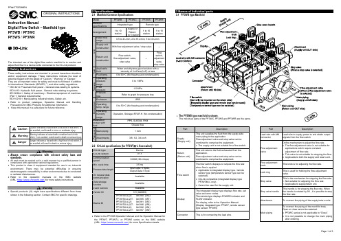
Page 1 of 3Instruction ManualDigital Flow Switch – Manifold type PF3WB / PF3WC PF3WS / PF3WRThe intended use of thedigital flow switch manifoldis to monitor and adjust fluid flow to a device while connected to the IO-Link protocol.These safety instructions are intended to prevent hazardous situations and/or equipment damage. These instructions indicate the level of potential hazard with the labels of “Caution,” “Warning” or “Danger.”They are all important notes for safety and must be followed in addition to International Standards (ISO/IEC) *1), and other safety regulations. *1)ISO 4414: Pneumatic fluid power - General rules relating to systems. ISO 4413: Hydraulic fluid power - General rules relating to systems.IEC 60204-1: Safety of machinery - Electrical equipment of machines. (Part 1: General requirements)ISO 10218-1: Manipulating industrial robots -Safety. etc.• Refer to product catalogue, Operation Manual and Handling Precautions for SMC Products for additional information. • Keep this manual in a safe place for future reference.CautionCaution indicates a hazard with a low level of risk which, ifnot avoided, could result in minor or moderate injury.WarningWarning indicates a hazard with a medium level of riskwhich, if not avoided, could result in death or serious injury.DangerDanger indicates a hazard with a high level of risk which, ifnot avoided, will result in death or serious injury.Warning• Always ensure compliance with relevant safety laws and standards.• All work must be carried out in a safe manner by a qualified person in compliance with applicable national regulations.• This product is class A equipment intended for use in an industrial environment. There may be potential difficulties in ensuring electromagnetic compatibility in other environments due to conducted or radiated disturbances.• Refer to the operation manuals on the SMC website (URL: https:// ) for more safety instructions.Warning• Special products (-X) might have specifications different from those shown in the following section. Contact SMC for specific drawings.2 Specifications2.1 Manifold Common Specifications2.2 IO-Link specifications (for PF3W7##-L flow switch)• Refer to the PF3WB Operation Manual and the Operation Manual for the PF3W7, PF3W7-L or PF3W5 series on the SMC website (URL: https:// ) for more Specification details.3.1 PF3WB type ManifoldPart DescriptionSupply(Supply unit)This unit supplies the fluid from the supply side main piping to the application.Flow adjustment valve and stop valve can be combined to comprise the equipment.• The supply unit is not suitable for a flow switch. Return(Return unit)This unit returns the fluid exhausted from the application.Flow adjustment valve and stop valve can be combined to comprise the equipment.Flow switch The flow switch displays or outputs the flow rate when flow is applied.• Applicable to integrated display type / remote sensor type (temperature sensor type can be selected).• IO-Link compatible (Integrated display type PF3W7##-L only).• Cannot be used for the supply unit.Display The integrated display type displays flow rate, set value and error codes.The remote type displays POWER indicator and FLOW indicator.For display, refer to the Operation Manual.(Display integrated type: PF3W7, remote sensor type sensor: PF3W5)Connector This is for connecting the lead wire.PartDescriptionLead wire with M8 connectorLead wire to supply power to and obtain output signals from the flow switchFlow adjustment valveOrifice mechanism to adjust the flow rate.• The flow adjustment valve is not suitable for applications which require constant adjustment of flow rate.• This valve is not suitable for stopping the flow. • Applicable to both the supply and return unit. Flow adjustment knob This knob is for adjusting the flow rate. Lock ringThis is used for holding the flow adjustment valve.Stop valveThis is the mechanism for stopping the flow rate. ∗: Not suitable for adjusting the flow rate. ∗: Applicable to supply/return unit.Stop valve handleThis handle is for stopping the flow rate. When the handle is rotated by 90°, it is possible to stop the flow rate.AttachmentTo connect the piping of the supply/return units. Main pipingTo connect the piping of the manifold body. Open or close cannot be selected.• PF3WC series is not applicable to “Close”. • It is not possible to change the main piping after ordering.ORIGINAL INSTRUCTIONSModel PF3WBPF3WCPF3WSPF3WRManifold specifications Integrated type Remote type Arrangement 1 to 10 stationSupply or Return: 1 to 5 station1 to 10 station1 to 10 stationU n i t Rated flow range 0.5 to 4 L/min, 2 to 16 L/min, 5 to 40 L/min Supply unit construction With flow adjustment valve / stop valve- Return unit construction Flow switch,flow adjustment valve,stop valve-Flow switch, adjustment valve, stop valveF l u i d Applicable fluid Water and ethylene glycol solution with aviscosity of 3 mPa •s(3 cP) or less Fluid temp. 0 to 90 o C (No freezing and condensation)P r e s s u r e Operating pressure range 0 to 1 MPa Proof pressure 1.5 MPaPressure loss Refer to graph for pressure lossE n v i r o n m e n tEnclosure IP65Operating temp. range 0 to 50 oC (No freezing and condensation)Operating humidity range Operation, Storage: 85%R.H. (No condensation)Materials in contact with fluidPPS, SUS304, FKMGrease free P i p i n g p o r tMain piping 1 inch Attachments 3/8, 1/2, 3/4 inch•The PF3WB type manifold is shown .The individual parts of the PF3WC, PF3WS and PF3WR are the same.4.1 InstallationWarning•Do not install the product unless the safety instructions havebeen read and understood.•Use the product within the specified operating pressure andtemperature range.•Tighten to the specified tightening torque.If the tightening torque is exceeded the mounting screws, brackets andthe product can be broken. Insufficient torque can cause displacementof the product from its correct position.•Do not drop, hit or apply excessive shock to the product.Otherwise damage to the internal parts can result, causing malfunction.•Do not pull the lead wire forcefully, and do not lift the product bypulling the lead wire (tensile force 49 N or less).4.2 EnvironmentWarning•Do not use in an environment where corrosive gases, chemicals, saltwater or steam are present.•Do not use in an explosive atmosphere.•Do not expose to direct sunlight. Use a suitable protective cover.•Do not install in a location subject to vibration or impact in excess ofthe product’s specifications.•Do not mount in a location exposed to radiant heat that would result intemperatures in excess of the product’s specifications.•Do not use the product in places where there are cyclic temperaturechanges.Heat cycles other than ordinary changes in temperature can adverselyaffect the inside of the product.4.3 Mounting•Never mount the product in a location where it will be used as a support.•Mount the product so that the fluid flows in the direction indicated bythe arrow on the product label or on the product body.•Check the flow characteristics data for pressure loss and the straightinlet pipe length effect on accuracy, to determine inlet pipingrequirements.•Do not sharply reduce the piping size.•The monitor with integrated display can be rotated. It can be set at 90ointervals clock and anticlockwise, and also at 45o and 225o clockwise.Rotating the display with excessive force will damage the end stop.•When a stop valve is mounted, rotate the monitor after closing the stopvalve handle.Rotating the monitor with excessive force with the stop valve open, themonitor and stop valve will interfere with each other, causing damage(refer to the figure below).4.4 Direct mounting (PF3W704 / 720 / 740)•When mounting the product, mount it to a panel with screws(equivalent to M6) using the mounting holes provided.•Mounting plate thickness should be approximately 3 mm.•Screws and nuts must be prepared by the user.The PF3WB uses 6 mounting screws, and the PF3WC, PF3WS and4.5 PipingCaution•Before connecting piping make sure to clean up chips, cutting oil, dustetc.•When installing piping or fittings, ensure sealant material does notenter inside the port.•Eliminate any dust left in the piping using an air blow before connectingthe piping to the product.•Ensure there is no leakage after piping.•When connecting piping to the product, hold the piping with a wrenchon the metal part of the piping (piping attachment) and main port of themain piping, which is integrated into the piping.•Using a spanner on other parts may damage the product.In particular, do not let the spanner come into contact with the M8connector. The connector can be easily damaged.After hand tightening, apply a spanner of the correct size to thespanner flats on the product, and tighten it for 2 to 3 rotations, to thetightening torque shown in the table below.If the tightening torque is exceeded, the product can be damaged. Ifthe correct tightening torque is not applied, the fittings may becomeloose.Nominal Thread size Tightening torque Width across flatsRc (NPT) 3/8 15 to 20 N•m 20.9 mmRc (NPT) 1/2 20 to 25 N•m 23.9 mmRc (NPT) 3/4 28 to 30 N•m 29.9 mmRc (NPT) 1 36 to 38 N•m 41.0 mm4.6 WiringCaution•Do not perform wiring while the power is on.•Confirm proper insulation of wiring.Poor insulation (interference from another circuit, poor insulationbetween terminals, etc.) can lead to excess voltage or current beingapplied to the product, causing damage.•Do not route wires and cables together with power or high voltagecables.Otherwise the product can malfunction due to interference of noise andsurge voltage from power and high voltage cables to the signal line.Route the wires (piping) of the product separately from power or highvoltage cables.•Keep wiring as short as possible to prevent interference fromelectromagnetic noise and surge voltage.Do not use a cable longer than 30 m. (IO-Link compatible device: 20m or less).•Ensure that the FG terminal is connected to ground when using acommercially available switch-mode power supply.•When an analogue output is used, install a noise filter (line noise filter,ferrite element, etc.) between the switch-mode power supply and thisproduct.4.7 Connector Wiring5 SettingsRefer to the Operation manuals on the SMC website(URL: https://) for the following Settings:Flow switch Setting and Function setting•Integrated display type: PF3W7•Integrated display type (IO-Link compatible): PF3W7-L•Remote type sensor: PF3W56.1 General MaintenanceCaution•Not following proper maintenance procedures could cause the productto malfunction and lead to equipment damage.•If handled improperly, compressed air can be dangerous.•Maintenance of pneumatic systems should be performed only byqualified personnel.•Before performing maintenance, turn off the power supply and be sureto cut off the supply pressure. Confirm that the air is released toatmosphere.•After installation and maintenance, apply operating pressure andpower to the equipment and perform appropriate functional andleakage tests to make sure the equipment is installed correctly.•If any electrical connections are disturbed during maintenance, ensurethey are reconnected correctly and safety checks are carried out asrequired to ensure continued compliance with applicable nationalregulations.•Do not make any modification to the product.•Do not disassemble the product, unless required by installation ormaintenance instructions.•How to reset the product after a power cut or when the power hasbeen unexpectedly removedWhen the flow switch is the integrated display type, the settings of theproduct are retained from before the power cut or de-energizing.The output condition also recovers to that before the power cut or de-energizing, but may change depending on the operating environment.Therefore, check the safety of the whole system before operating theproduct.7 Troubleshooting7.1 Error indication (PF3W7 Integrated display type)When using PF3W7 integrated display or PF3W5 remote sensorWhen PF3W7-L (IO-Link) is used in SIO modeNo. Name Wire colour Function1 DC(+) Brown 12 to 24 VDC2 N.C./ OUT2 White N.C. / Switch output 2 (SIO)3 DC(-) Blue 0 V4 OUT1 Black Switch output 1 (SIO)When PF3W7-L (IO-Link) is used as IO-Link deviceNo. Name Wire colour Function1 L+ Brown 18 to 30 VDC2 N.C./ OUT2 White N.C. / Switch output 2 (SIO)3 L-Blue 0 V4 C/Q BlackIO-Link data /Switch output 1 (SIO)∗: Wire colours are for the lead wire included with the PF3W7 series.Page 3 of 37.2 Error indication (PF3W5 Remote sensor type) If the error cannot be reset after the above measures are taken, or errors other than the above are displayed, please contact SMC.Refer to the Operation manual on the SMC website (URL: https:// ) for more detailed information about Troubleshooting.8 How to OrderRefer to the operation manual or catalogue on the SMC website (URL: https:// ) for How to order information.9 Outline Dimensions (mm)Refer to the Operation manual on the SMC website (URL: https:// ) for outline and mounting dimensions for the PF3WB, PF3WC, PF3WS and PF3WR.10.1 Limited warranty and Disclaimer/Compliance Requirements Refer to Handling Precautions for SMC Products.11 Product disposalThis product should not be disposed of as municipal waste. Check your local regulations and guidelines to dispose of this product correctly, in order to reduce the impact on human health and the environment.12 ContactsRefer to or www.smc.eu for your local distributor / importer.URL: https:// (Global) https:// (Europe) SMC Corporation, 4-14-1, Sotokanda, Chiyoda-ku, Tokyo 101-0021, Japan Specifications are subject to change without prior notice from the manufacturer. © 2021 SMC Corporation All Rights Reserved. Template DKP50047-F-085M。
SMC 冷冻式空气干燥机 使用说明书

IDX-OM-W093-B 使用说明书机种名称冷冻式空气干燥机型式 / SeriesIDF60-20-A,C,L,R,T,V IDF60-30-A,C,L,R,T,VIDF70-20-A,C,L,R,T,V IDF70-30-A,C,L,R,T,VIDF80-20-A,C,L,R,T,V IDF80-30-A,C,L,R,T,VIDF90-20-A,C,L,R,T,V IDF90-30-A,C,L,R,T,V本使用说明书对产品的安装及运行进行了说明。
请由充分理解本产品的基本运行方法,或具备工业设备的使用方面的基本知识、能力的人进行作业。
请妥善保管本使用说明书,以便随时使用。
需要英文说明书的场合,请通过我公司网站下载。
URL:/English instruction manual can be downloaded from our URL:/前言首先,非常感谢您购买SMC冷冻式空气干燥机(以下简称「本产品」)。
为保证您长期安全使用本产品,请务必认真阅读本使用说明书(以下简称「本书」),并在充分理解其内容的基础上进行操作。
●请务必遵守本使用说明书中所记载的警告·注意事项,及ISO4414*1) JIS B8370*2)和其他安全相关规则。
*1) ISO4414:Pneumatic fluid power – Recommendations for the application of equipment to transmission and control systems.*2) JIS B8370:空气压系统通则●本书对本产品的安装及运行进行了说明。
请由充分理解本书所示的基本运行方法,或具备工业设备的使用(安装及运行)方面的基本知识、能力的人进行作业。
●本产品附带的本书及其它资料的内容属于合同条款的一部分,不能对已达成的协定、约定或关系进行修改或变更。
●禁止未经本公司授权,把本书的任何内容复印给第三者使用。
SMC 气动元件产品说明书
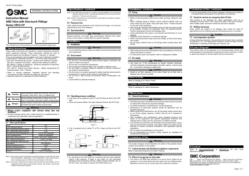
VR12F-TF222-005ENPage 1 of 1Instruction ManualAND Valve with One-touch FittingsThe intended use of this product is to control pneumatic signal lines.These safety instructions are intended to prevent hazardous situations and/or equipment damage. These instructions indicate the level of potential hazard with the labels of “Caution,” “Warning” or “Danger.” They are all important notes for safety and must be followed in addition to International Standards (ISO/IEC) *1), and other safety regulations. *1)ISO 4414: Pneumatic fluid power - General rules relating to systems. ISO 4413: Hydraulic fluid power - General rules relating to systems.IEC 60204-1: Safety of machinery - Electrical equipment of machines. (Part 1: General requirements)ISO 10218-1: Robots and robotic devices - Safety requirements for industrial robots - Part 1: Robots.• Refer to product catalogue, Operation Manual and Handling Precautions for SMC Products for additional information. • Keep this manual in a safe place for future reference.Warning • Always ensure compliance with relevant safety laws and standards.• All work must be carried out in a safe manner by a qualified person in compliance with applicable national regulations.2 SpecificationsNote 1) Use caution when the maximum operating pressure is used with soft nylonand polyurethane. Depending on the temperature, these tubes have a lower operating pressure. Refer to the specification of the tubes.Note 2) Two axes (horizontal and vertical) and two directions were tested, and nomalfunction of the valve occurred (pulse shape: sine shape), 3 times (test sample mounted with bracket).Note 3) No malfunction occurred in a sweep cycle test between 10 to 150 Hz atvibration sweep 0.35 mm. The test was performed in the two axes and two directions, 7 min per cycle (20 cycles).Note 4) Brass components are all electroless nickel plated as standard. (Copper-free and fluorine-free)2.2 Response timeValve response time depends on the overall circuit design, so it must be determined by the circuit designer. 2.3 Special productsWarningSpecial products (-X) might have specifications different from those shown in this section. Contact SMC for specific drawings.3 Installation3.1 InstallationWarning• Do not install the product unless the safety instructions have been read and understood. 3.2 EnvironmentWarning• Do not use in an environment where corrosive gases, chemicals, salt water or steam are present.• Do not use in an explosive atmosphere.• Do not expose to direct sunlight. Use a suitable protective cover.• Do not install in a location subject to vibration or impact in excess of the product’s specifications.• Do not mount in a location exposed to radiant heat that would result in temperatures in excess of the product’s specifications.• Do not use in high humidity environment where condensation can occur.• Contact SMC for altitude limitations.3.3 Operating pressure conditions• Only when air is supplied to both P1 and P2 does air flow to the OUT side.• When air pressure differs, the lower pressure flows to the OUT side.Figure 1.• If air is supplied only to either P1 or P2, it does not flow to the OUT side.Figure 2.Warning• Air may flow to the OUT side for a moment until the valve switches (About 1/100 second). If there is any effect on the connected equipment due to the above air flow, install a speed controller, etc, on the OUT side, and adjust to prevent this effect before use.3.4 PipingCaution• Before connecting piping make sure to clean up chips, cutting oil, dust etc.• When installing piping or fittings, ensure sealant material does not enter inside the port. When using seal tape, leave 1 thread exposed on the end of the pipe/fitting.• Stop using the equipment immediately when air leaks are large enough to be audible, or when the equipment does not operate properly. Perform appropriate function and leakage tests.• Check periodically that piping is not loosened and that there is no air leakage.• Regularly check that there is no external damage.• When connecting tubes using One-touch fittings, provide some spare tube length.• Do not apply external force to the fittings when binding tubes with bands.Caution• SMC products have been lubricated for life at manufacture, and do not require lubrication in service.• If a lubricant is used in the system, refer to catalogue for details. 3.5 Air supplyWarning• Use clean air. If the compressed air supply includes chemicals, synthetic materials (including organic solvents), salinity, corrosive gas etc., it can lead to damage or malfunction.Caution• Install an air filter upstream of the valve. Select an air filter with a filtration size of 5 μm or smaller.4 How to OrderRefer to catalogue for ‘How to Order’.5 Outline DimensionsRefer to catalogue for outline dimensions.6 Maintenance6.1 General maintenanceCaution• Not following proper maintenance procedures could cause the product to malfunction and lead to equipment damage.• If handled improperly, compressed air can be dangerous.• Maintenance of pneumatic systems should be performed only by qualified personnel.• Before performing maintenance, turn off the power supply and be sure to cut off the supply pressure. Confirm that the air is released to atmosphere.• After installation and maintenance, apply operating pressure and power to the equipment and perform appropriate functional and leakage tests to make sure the equipment is installed correctly.• If any electrical connections are disturbed during maintenance, ensure they are reconnected correctly, and safety checks are carried out as required to ensure continued compliance with applicable national regulations.• Do not make any modification to the product.• Do not disassemble the product, unless required by installation or maintenance instructions.7 Limitations of UseWarningThe system designer should determine the effect of the possible failure modes of the product on the system.7.1 Limited warranty and disclaimer/compliance requirements Refer to Handling Precautions for SMC Products.Warning7.2 Effect of energy loss on valve state• The valve is an AND logic element in an all-air circuit. When the air pressure is cut to both inputs the valve goes into an undefined state. Backflow of air from out to in port may occur under this condition.• It is the responsibility of the system designer to determine the effect in the system when air pressure is cut and when it is restored. 7.3 Cannot be used as an emergency shut-off valveThis product is not designed for safety applications such as an emergency shut-off valve. If the valves are used in this type of system, other reliable safety assurance measures should be adopted.7.4 Holding of pressureSince valves are subject to air leakage, they cannot be used for applications such as holding pressure (including vacuum) in a system.Caution7.5 Low temperature operationUnless otherwise indicated in the specifications for each valve, operation is possible to -5˚C, but appropriate m easures should be taken to avoid solidification or freezing of drainage and moisture, etc.8 Product DisposalThis product shall not be disposed of as municipal waste. Check your local regulations and guidelines to dispose this product correctly, in order to reduce the impact on human health and the environment.9 ContactsRefer to or www.smc.eu for your local distributor/importer.URL : https:// (Global) https:// www.smc.eu (Europe) SMC Corporation, 4-14-1, Sotokanda, Chiyoda-ku, Tokyo 101-0021, JapanSpecifications are subject to change without prior notice from the manufacturer. © 2022 SMC Corporation All Rights Reserved. Template DKP50047-F-085MORIGINAL INSTRUCTIONS2 (OUT)(IN) 1 (IN) 1IN P 1 IN P 2 OUT OUTOUT IN P 1 IN P 2 IN P 1 IN P 2。
- 1、下载文档前请自行甄别文档内容的完整性,平台不提供额外的编辑、内容补充、找答案等附加服务。
- 2、"仅部分预览"的文档,不可在线预览部分如存在完整性等问题,可反馈申请退款(可完整预览的文档不适用该条件!)。
- 3、如文档侵犯您的权益,请联系客服反馈,我们会尽快为您处理(人工客服工作时间:9:00-18:30)。
真空吸盘是消耗品,其产品保证期限是从购入后 1 年之内。 但,即使在保证期限内,因使用真空吸盘导致的磨损或橡胶材质劣化等情况不在保证范围内。
『适合用途的条件』
出口海外时,请务必遵守经济产业省规定的法令(外国汇兑及外国贸易法)、手续。
否则可能会导致产品内部破损或误作动。
·请勿用力拉拽导线,或拉拽导线搬运本体。(拉伸强度为 49N 以内)
使用时请手持本体。 否则会造成产品破损、故障、误作动。
·对产品配管时,请用扳手夹住与配管部一体的金属部位(管路配件)进行配管。
若在其它部位使用扳手,可能导致产品破损。 特别是不能在 M8 连接器上使用扳手。 否则会导致连接器破损。
②请具有充分的知识和经验的人员使用本产品。 在此所述产品若误操作会损害其安全性。 机械·装置的组装、操作、维修保养等作业请由具有充分知识和经验的人进行。
③请务必在确认机械・设备的安全之后,再进行产品的使用和拆卸。 1.请在确认已进行了移动体的落下防止对策和失控防止对策之后再进行机械·设备的使用和维护。 2.请在确认已采取上述安全措施,并切断了能量源和设备电源以保证系统安全的同时,确认和理解设备上产
品个别注意事项的基础上,进行产品的拆卸。 3.重新启动机械·设备时,请对意外动作·误操作采取预防措施。 ④在下述条件和环境下使用时,请在考虑安全对策的同时,提前与本公司咨询。 1.明确记载的规格以外的条件或环境,以及屋外或阳光直射的场所。 2.使用于原子能、铁路、航空、宇宙设备、船舶、车辆、军用、医疗设备、饮料•食品用设备、燃烧装置、
使用除此以外的流体不能确保精度,请多加注意。 使用流体中不能含有合成油(含化学药品、有机溶剂)、盐分、腐蚀性气体等物质。 若这些物质混入流体中,会造成产品破损及作动不良。 请详细确认规格后再使用。
・使用高温流体时,请勿触摸配管连接部及配管处。
否则可能导致烫伤。
・随着流体温度,额定压力范围・耐压力会变化。
·请吹净配管内残留的异物等,再与产品进行配管。
否则会导致故障、误作动。
·请结合产品标牌和本体上标注的流体流向进行设置、配管作业。
由于空气的滞留,有可能无法正确测量。
·配管时请避免开关 IN 侧的配管尺寸急剧变化。
配管尺寸急剧缩小或 IN 侧有阀等节流的情况下,配管内的流速分布会混乱,无法正确测量。因此,这种措施请在开 关的 OUT 侧实施。 另外,开放 OUT 侧,或过流量状态下容易产生气穴现象,可能无法正确测量。对策是提高流体压力,减弱气穴现象。 在开关的 OUT 侧设置节流等,确认没有误动作后再使用。 在 OUT 侧的节流完全关闭的状态下,泵开始工作时可能会因脉冲(压力变动)的影响使开关发生误动作,所以请确 认没有误动作后再使用。
●关于使用 * 安装 ·请遵守紧固力矩。
超出紧固力矩范围拧紧的话,可能会导致安装螺钉、安装件、产品等损坏。 另外,紧固力矩不足时,可能会造成产 品安装位置偏移及连接螺纹部松动的情况。 (请参考 16 页的安装·配置。)
·使用市场购买的开关电源时请将 FG 端子接地。 ·请不要在有振动和冲击的环境中使用。
若混入气泡,可能无法正确测量。 (流路内是完全注水状态就没有问题。) 特别是上下倒置垂直安装时,可能会因水滴滴落而加速产品破损,所以请多加注意。
『保证以及免责事项』
① 本公司产品的保证期间为,从开始使用 1 年内,或者从购入后 1.5 年内。以其中最先到达的时间为 期限。 ※3) 另外产品有最高使用次数,最长行走距离,更换零件周期等要求,请与最近的营业所确认。
② 保证期间内由于本公司的责任,产生明显的故障以及损伤时,将由本公司提供代替品或者进行必要 的零件更换。 在此所述的保证,是指对本公司产品的保证,将由于本公司产品导致的其他损害,不在我们的保证 范围内。
※2) 劳动安全卫生法等
注意: 误操作时,有人员受伤的风险,以及仅有物品破损的风险的事项。
警告: 误操作时,有人员受到重大伤害甚至死亡的风险的事项。
危险: 是紧迫危险状态,如不回避会有人员受到重大伤害甚至死亡的风险的事项。
警告
①本产品的适合性由系统设计者或规格制定者来判断。 因为本产品的使用条件多样化,所以请由系统的设计者或规格的制定者来判断系统的适合性。必要时请通 过分析和试验进行判断。对于本系统预期的性能、安全性的保证由判断系统适合性的人员负责。请在参考 最新的产品资料,确认规格的全部内容,且考虑到可能发生的故障的基础上构建系统。
·请避免铁丝等进入流路内。
否则会造成传感器破损、故障、误作动。
·请勿将开关安装于可能被脚踏的场所。
由于失误踩踏给开关施加过大的负载,有可能导致破损。
·流体中可能混入异物时,请在 IN 侧安装过滤器。
若异物付着在开关旋涡发生体或旋涡检测体上,将不能正确测量。 推荐使用 40 筛目程度的过滤器。
·设计、安装时请保证液体能够一直注满检测流路。 ·垂直安装时,请让液体从下向上流动。
文件 No.PF※※-OMM0004-D
使用说明书
产品名称
数字式流量开关
型式 / 系列 / 型号
PF3W7##
SMC 有限公司
目录
安全注意事项 型式显示・型号体系 产品各部的名称 配线方法 流量设定 功能设定 工厂出货时的设定 F1 OUT1 的设定 F2 OUT2 的设定 F3 响应时间的设定 F10 子画面的显示内容选择 F20 外部输入的设定 F22 模拟输出的设定 F30 累计保持功能 F80 省电模式的设定 F81 密码输入的设定 F82 线名的输入 F90 全项目设定 F98 输出确认 F99 恢复出厂状态 其他设定 维护 故障一览表 规格 规格表 特性表 模拟输出 外形尺寸图 订制规格
■请勿在易燃性的液体及渗透性高的液体中使用。
有导致火灾及爆炸、破损、腐蚀的风险。
禁止
■请不要在发生静电的场所中使用
会造成系统不良及故障。
禁止 指示 指示
■在互锁回路中使用的场合 ·请设置由其他系统构成的(机械式保护功能等)多重互锁回路。 ·进行是否正常动作的检查
否则可能因误作动引发事故。
■维修保养时 ·请切断供给电源 ·请停止流量的供给
注意
我公司产品不能作为法定计量仪器使用。 我公司制造、销售的产品没有进行各国[计量法]所指定机关的认证申请,并不是取得计量法相关型式认证试 验和检定的计量器、计测器。 因此,我公司产品不能使用于各国计量法中规定的交易或证明为目的的用途。
-3-
No.PF※※-OMM0004-D
■图标的说明
图标
图标的含义 禁止(绝对不允许做)。 具体的禁止内容在图标中或在附近用图形和文字进行指示。
强制行为(必须做)。 具体的强制内容在图标中或在附近用图形和文字进行指示。
■关于操作者
①本使用说明书是面向对使用气动元件的设备·装置进行组装·操作·维修保养具有足够知识和经验 的人员。 组装·操作·维修保养的实施,也仅限于此类人员。
②请在充分阅读本使用说明书并理解其内容的基础上实施组装·操作·维修保养。
·组合直流电源请使用以下的 UL 认证品。
符合 UL1310 要求的等级 2 电源单元或符合 UL1585 要求的等级 2 变压器作为电源的最大 30[Vrms] (42.4[V 峰值])以下的回路(等级 2 回路)
·只有在产品本体和标牌上有 标记时,才是 UL 认证品。 ·请使用规定的电压。
若使用规定以外的电压,可能会造成故障、误作动。 在低于规定电压时,因产品的内部电压降低,可能发生负载不作动的情况。 请确认负载的动作电压后再使用。
娱乐器械、紧急切断回路、冲压机用离合器・刹车回路、安全设备等的使用,以及用于非产品手册中的标 准规格的场合。 3. 预测对人身和财产有重大影响,特别是在有安全要求的场合使用时。 4.用于互锁回路时,请设置应对故障的机械式保护功能,进行双重互锁。 另外进行定期检查以确认是否正常作动。
-2-
No.PF※※-OMM0004-D
注意
本公司产品是面向制造业提供的。 现所述的本公司产品主要面向制造业且用于和平使用的场所。 如果用于制造业以外的用途时,请与本公司联系,根据需要交换规格书、签订合同。 如有疑问,请向最近的营业所咨询。
■保证以及免责事项/适合用途的条件 本产品适用于下述“保证以及免责事项”、“适合用途的条件”。 请在确认、允许下述内容的基础上,使用本公司产品。
这些注意事项,按照危害和损伤的大小及紧急程度分为「注意」「警告」「危险」三个等级。 无 论哪个都是与安全相关的重要内容,所以除了遵守国际规格(ISO/IEC)、日本工业规格(JIS)※1)以及其 他安全法规※2)外,这些内容也请务必遵守。
※1) ISO 4414:Pneumatic fluid power -- General rules relating to systems. ISO 4413:Hydraulic fluid power -- General rules relating to systems. IEC 60204-1:Safety of machinery --Electrical equipment of machines. (Part1:General requirements) ISO 10218-1992:Manipulating industrial robots -Safety JIS B 8370:空气压系统通则 JIS B 8361:油压系统通则 JIS B 9960-1:机械类的安全性-机械的电气装置((第 1 部:一般要求事项) JIS B 8433-1993:工业用操作机器人-安全性等
可能会造成人员受伤。
-4-
No.PF※※-OMM0004-D
禁止接触 禁止接触
指示
注意
■通电中请勿触碰端子、连接器