
Parker DC590中文版
派克汉尼汾流体传动产品(上海)有限公司上海市金桥出口加工区云桥路280号201206
86 21 2899 500086 21 5834 8975
北京市朝阳区光华路7号汉威大厦21层B2109室100004
86 10 6561 052086 10 6561 0526
广州市天河区体育东路138号金利来中心1706室510620
可选择顶部外置通风模块。
配有冷却风扇组件,可选择柜顶安装或调速器安装。
若选择调速器安装,需在总高度上增加+150mm
FRAME 3
FRAME 4
D
W
H
D
W
H
FRAME 5FRAME H
D
W H
D
W
H
FRAME 6
FRAME 1
FRAME 2
W
H
D
W H
D
W
H
:9+/&! :9 :h_l[ ?dj[]hWjeh I[h_[i (派克新一代DC590+
直流调速器15A-2700A
产品简介
依托30多年的直流调速器设计经验,派克新推出了新一代DC590+调速器,该调速器展现了直流调速器技术的发展前景。
凭借其创新的32位控制架构,DC590+的灵活性和功能性足以满足所有应用的要求。
无论是简单的单电机驱动,还是高要求的多电机驱动系统,这些
问题都会迎刃而解。
DC590+也可以应用于系统方案,
称为DRV。
它是一个集成模块,
涵盖了所有相关电气部件。
作为直
流调速器产品系列的组成部分,这
一创新方法从根本上缩减了设计时
间,节省了面板空间,布线时间和
成本。
DRV的概念是独一无二的,
它来自各行业数以千计的成功应用
经验。
作为直流调速器产品系列的
组成部分,DC590+进一步巩
固了派克调速器作为直流驱
动技术市场领导者的地位。
先进的控制结构
• 更快的响应速度
• 更好的控制能力
• 更多的数学和逻辑功能模块
• 加强的检测和编程功能
• 与派克其它系列调速器通用
的编程工具
依靠32位R I S C处理器的升
级,DC590+系列有了更强的
功能性和更高的灵活性,使其
能适用于更多的复杂应用。
系统应用
过程控制
简单应用
产品总览图
12安培 32安培2700安培
新一代技术
基于全球数千种应用中的高度成
功,DC590+调速器将直流驱动控
制带向了一个新的水平。
由于其一
流的高级32位控制架构,DC590+
调速器提供了适用于一系列工业用
途的灵活高效的控制系统。
派克在直流领域拥有行业内一流的
经验和技术,向那些最苛刻的驱动
控制应用提供控制系统。
拥有从15
安培到2700安培的各类调速器,派
克可以向各种应用系统提供最佳的
解决方案。
典型应用系统
• 冶金
• 塑料及橡胶加工机械
• 电线电缆
• 物料输送系统
• 机床
• 包装
功能模块编程
功能块编程是一种非常灵活的控制
结构,它的多种组合使得用户功能
易于实现。
每个控制功能采用(例如
输入,输出,PID程序)软件模块的
形式,可以与其它所有模块自由连
接,提供各种需要的操作。
调速器出厂时已设置为标准直流调
速器模式,含有预设的功能模块,
这样您就可以直接运行而无需进一
步调试。
您也可以选择预先定义的
宏或者创建您自己的控制策略,通
常这样都可以降低对外部PLC的需
求,从而降低成本。
反馈选项
DC590+有一系列接口选项,与最
常见的反馈装置相兼容,适用范围
从简单驱动控制到最复杂的多驱动
系统控制,对反馈接口无要求的
话,电枢电压反馈为标准配置。
• 模拟测速发电机
• 编码器
• 光纤编码器
接口选项
设计时出于连接性能的考虑,
DC590+有许多通信和输入/输出选
件,使得调速器可以独立实施控
制,也可以集成到一个更大的系统
中去。
当与功能编程相结合时,我
们可以很容易的根据需要进行功能
模块创建和控制,这样就为用户提
供了一个灵活多用的平台来进行直
流驱动控制。
编程/操作控制
操作面板有着直观的菜单结构而且
符合人体工程学设计。
通过明亮的
易于阅读的背光显示屏和触摸键
盘,我们可以便捷地访问调速器各
种参数和功能模块。
此外,它还提
供了本地启动/停止控制,速度调节
和旋转方向控制,能极大地帮助机
器调试。
• 多语言字母数字显示
• 设置参数值和图例
• 调速器安装或远程安装
• 本地启动/停止,速度和方向控制
• 快捷设置菜单
连接性
无论您的控制模式多么复杂,
DC590+都有与之相匹配的接口,
为最复杂的应用系统准备了足够
的模拟和数字I/O接口。
另外还有
相关的技术卡,可以使用串口通
信和现场总线网络。
DC590+的设
计使得其可以在任何控制环境中
完美的使用。
模拟/数字控制
• 5路模拟输入 (12位带正负符号)
• 3路模拟输出
• 9路数字输入
• 3路数字输出
串口通信和现场总线选件
• Profibus
• Ei Bisynch
• Canopen
• Link
• Lonworks
• Devicenet
• RS422/RS485
• Modbus
• Controlnet
• Ethernet
6901 编程/操作控制板
DRV --- 整体直流驱动技术
DC590+可用作单一模块使用,
也可选择“DRV”形式使用。
DRV是一个自成一体的驱动系
统,它包括所有的外围功率元
件,与直流调速器相连,安装在
在调速器下方的空间里。
DRV包括
• 交流进线接触器
• 交流进线熔断器
• 直流熔断器(针对可逆型)
• 控制/磁场回路快熔
• 电动机鼓风起动器(可选)
• 辅助控制电源变压器(可选)
为您节省
• 设计时间
• 面板空间
• 元件装配和布线
• 元件选购时间
• 时间和成本
传统的直流驱动
电控柜
同功率的590+ DRV,
如图面板空间得以节省
电动机
鼓风起动器
直流熔断器
交流进线
熔断器
控制/磁场回路熔断器
交流线路接触器。
DC590+集成器系列2 DC驱动器(15-2700A,0.75-1500KW)商品说明书
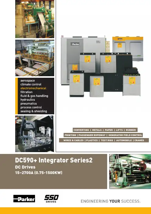
590+ Integrator Series 2DC Drives15–2700A).75 to 1500KW(The DC590+ Integrator series is a highly advanced DC drive meets the demands of themost complex motor control applications. Extensive application software (includingwinder control) as standard together with Function Block Programming andconfigurable I/O creates a total drive system in a single module.The DC590+ Integrator Series 2 sees the next step in the development of DC drivetechnology, derived from over 30 years experience in designing DC drives. With itsinnovative 32-bit control architecture, the DC590+ has the flexibility and functionality tomore than meet the requirements of all applications, from basic motor installationsthrough to the most demanding systems.Advanced Control ArchitectureBenefitting from the improvedperformance of a 32-bit RISCprocessor, the DC590+ IntegratorSeries 2 delivers enhancedfunctionality and increased flexibility,making it suitable for use in a widerrange of more complex applications.• Faster drive response• Greater control capabilities• Increased maths and logicfunction blocks• Enhanced diagnostic andprogramming functionality• Common programming toolswith rest of drives platform SPECIFICATIONS:Power Configuration:Overload :Armature Voltage :AC Supply Voltage 50/60Hz:Ambient:590+ Four Quadrant Regenerative; 2 Fully Controlled Three Phase Thyristor Bridges591+ Two Quadrant Non Regenerative; 1 fully controlled Three Phase Thyristor BridgeThyristor Controlled Variable Field SupplyEasily configurable to 12 pulse operation with minimal software modification200% for 10sec ; 150% for 30secV=V x1.15armature ac220- 690V (±10%)0-45°C ( Derate 1%/°C for higher ambient to 55°C max)High Energy MOV's Motor Over temperatureInstantaneous Overcurrent Heatsink Over temperatureInverse Time Overcurrent Thyristor Trigger FailureField Failure Interline Snubber NetworkSpeed Feedback Failure Zero Speed DetectionStandstill Logic Stall ProtectionFrame 1: 4A , Frame 2 & 3: 10A , Frame 4& 5 : 30AProtection:Field Current:Field Voltage::V= V x 0.82field acAltitude:500m ASL (Derate 1%/200m above 500m to 5000m max )Analogue Inputs (5 Total - 1 x 12 bit plus sign , 4 x 10 bit plus sign)5 - ConfigurableAnalogue Outputs (3 Total - 10 bit)1 - Armature Current Output (-10/0/+ 10V or 0-10V)2 - ConfigurableDigital Inputs (9 Total - 24V, max 15mA)1 - Program Stop1 - Coast Stop1 - External Trip1 - Start/Run5 - ConfigurableDigital Outputs (3 Total - 24V(max 30V) 100mA)3 - ConfigurableReference Supplies1 : +10V DC1: +24V DC1: -10V DC3: 0 V DCInputs/Outputs:(Details on higher ratings will be provided on request)FIELDBUS OPTIONS• Profibus-DP • Ei BisynchTM• Canopen • Fibreoptic Link• Controlnet • Ethernet• Lonworks • Devicenet• RS422/RS485 • Modbus RTUFEATURESIN-BUILT FUNCTIONS FOR DIAMETERCALCULATION,TORQUE CALCULATION, TAPERCALCULATION, PID CONTROL, SPEED DEMANDCALCULATION, COMPENSATION CALCULATION,SETPOINT SUMMATIONPRESETSMOPDC 590+Integrator Series 2FeaturesMAN MACHINE INTERFACEcommissioning.Multi-lingual and alpha numeric displayCustomized parameter values and legendsOn drive or remote mountingLocal control of start /stop, speed and directionQuick set up menuBack lit display with dual line alpha numericdisplay supporting plain Engilsh textconfiguration4 line display (optional)The 590+ has a range of interface optionswhich are compatible with the most commonfeedback devices. Armature voltage feedbackis standard without the need for any interfaceoption.Analog TachometerEncoderPlastic Fiber MicrotachGlass Fiber MicrotachLINK -HIGH SPEED DRIVESCOMMUNICATIONSLINK is Parker SSD Drives' advanced fiber opticnetwork for multi-drive process controlsystems. It allows distributed control elementsincluding drives, operator stations and I/Omodules to be interconnected into highlyefficient cost effective networks. Being fiberoptic based,it provides ultra high speed(3Mbaud, upto 300 nodes in a network) errorfree communications between each node of thesystem. Gateways to the principle Fieldbusprotocols enable LINK to be seamlesslyintegrated into wider networks.INTERFACE OPTIONSWhatever the complexity of your control scheme,the 590+ has the interface to suit. As standardthere's enough analog and digital I/O for themost complex applications. Alternatively, addthe relevant 'technology box' for immediateaccess to serial communications and Fieldbusnetworks. The 590+ has been designed to fitseamlessly, and without compromise, into anycontrol environment. This control board is samefor all the frames and so the spares are readilyavailable.ANALOG/DIGITAL CONTROL5 Analog Inputs3 Analog Outputs9 Digital Inputs3 Digital OutputsSTANDARDSThe 590+ series meets the following standardswhen installed in accordance with the relevantproduct manuals.CE marked to EN50178 (safety, low voltagedirective)EN61800-3 (EMCcompliance) with integralfilters (590+ up to110A require external supplycapacitors for compliance)DSE Lite software can be used the 890, 690+, 650V, 590+ series range ofdrives available from SSD Drives and works with Windows XP™ andWindows Vista™ operating systems.DSE Lite combines the features of CE Lite (Configuration Editor Lite) andDSD (Drive System Designer), the two previous software products for driveconfigurations, into a single application with a modern interface and moreadvanced features. This new software supports user-defined configurationsand offers real-time monitoring and charting, with on-line help facility fordrive function blocks. It can extract drive parameters into an open template.The 'frame' dependant parametersin the templates are displayed incolor.In this software, the unique featureof accessing data online onoscilloscope is also available. TheOscilloscope will set-up a real-timedata acquisition facility inside thedrive firmware, wait for data to beready, retrieve the data and display it.This is a tool to capture and displayfast signals from external or internaltriggers. You can add a parameter tothe Oscilloscope either from anONLINE configuration or from theONLINE Parameter View.DSE LiteDrive System Explorer (DSE) Lite is the new drive configuration softwaretool , with the help of which drive configuration has now becomeuncomplicated and effortless. This new addition from Parker SSD Drivesmakes the drive configuration so quick and simple that the design andproduction engineers can now minimize the set up and configuration time ofdrive to improve their efficiency.Software ToolsPreset SpeedsDiameter CalculationTorque CalculationSectional Control4- Q RegenMacros available for several applicationsto configure entire Draw Sections,Current Winders and Speed WindersParker SSD Drives-India-Catalogue-DC Integrator Series 2 (Issue 2, November’2011)Product Upgradation is a continuous process, hence, data in this catalog is subject to change without prior notice. For latest information, please get in touch with our Sales Offices.Plotno:EL30,MIDCTTC,IndustrialArea,Mahape,NaviMumbai,Maharashtra-400709,Phoneno*************,FaxNo**************SwaminarayanTemple,Judge’sBunglowRoad,Vastrapur,Ahemedabad-380015,Gujarat,Telefax-0794******************** Noida: CS - 171, 7th Floor, Tower A,The Corenthum, Plot No. A41, Sector 62,Noida 201 301, UP , Phone no:0120 4742920 (Recep), 0120 4742900-919, Fax No:0120 4742914 * Bangalore: V-2 (A), 14th Cross, 2nd Stage, Pennya Industrial Estate, Bangalore 560 058, Tel/Fax no: 080-2836 3976/77/78 * Hyderabad: #26-29,18-19,16A,Phase IV,I.D.A, Patancheru, Dist: Medak-502 319, Andhra Pradesh , Phone no : 08455-248731(Direct) * Kolkata: B 502, 5th Floor, City Centre, Sector-1,SaltLake,Kolkata-700064,WestBengal,Phoneno************/6/7,FaxNo************:North: :South::East:180, 270A Frame 3380, 500, 725, 830 AFrame 4:Automation Head Office:Parker Hannifin India Pvt LtdAutomation Group Plot no P41/2, Eight AvenueDomestic Traffic Area Mahindra World City Chengalpattu , Kancheepuram District - 603002Phone no : +91(044) 43910799Fax no : +91(044) 43910700mitali.nair@parker .comwww.parker .com,TrainingParker organizes In- house and customized Quality SystemsPremier Customer Servicemeasures on-time delivery each day based on customer Request Date… We deliver To field available through domestic and international teams of service engineers. An experienced staff around-the-clock product support service to help Sophisticated Project Engineering Tools are used at Parker –••• development tools for drives,all popular PLCs and HMIsSystem Solutionsthe a youFunction Block Programming is a tremendously flexible control structure that allows an almost infinite combination of user functions to be realized with ease. Each control function (an input, output, process PID for example) is represented as a software block that can be freely interconnected to all other blocks to provide any desired action. The drive is despatched with the function blocks pre-configured as a standard dc drive so you can operate it straight from the box without further adjustments.There are over 100 function blocks including...The Power of Function Block ProgrammingValue FunctionsLogic FunctionsSet point SummingfunctionSpeed Demand CalculationPID Control。
590+ 中文快速启动手册 规格 1
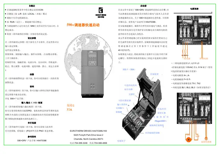
三相电源
控制电源
·三相电源连接到 L1, L2 和 L3
规格 1(35A)
控制装置
·控制电源连接 115VAC 的 L 和 N 端子(使用 可选的控制变压器时不需要) ·电机电枢接 A+, A-
·电机励磁接 F+和 F-
可选的电机风 扇启动器
·电机温度传感器连接 Th1, Th2 ·风机连接 BL1, BL2, BL3(如果安装的话)
·电枢电压是默认的速度反馈模式因而不需要反馈卡。 ·提供有 4 个反馈卡。模拟测速计、编码器、丙烯微型测 速计和玻璃微型测速计。 ·选择合适的反馈卡。如图中的箭头所示,将反馈卡安装 在反馈头上。确保所有的传输线固定器固定就位。 ·在模拟测速计的卡上,根据最大速度时的测速计输出电 压,以个、十和百为单位设定开关设定值。 ·直流模拟测速计:G3(+), G4(-)。将开关设定到 DC ·交流模拟测速计:G1, G2。将开关设定到 AC ·编码器:E1=0V, E2=+, E3,E4=A,A-, E5,E6=B,B·微型测速计:C1=0V, C9=24V, F1=光纤接收
速度反馈
·紧急停继电器常开触点在 B8 和 C9 之间 ·紧急停继电器常开 TDD(时间延迟跳闸)触点在 B9 和 C9 之间 ·跳线 C1 和 C2(如果没有外部跳闸触点) ·跳线 C5 和 C9 用于内部启用触点 ·C3 和 C9 之间的启动触点 ·C4 和 C9 之间的点动触点 ·B6(+)和 C1(-)之间的状态正常继电器线圈(24V)
完成时按e使用向上和向下箭头输入额定的电机功率速度基准速度电位器跨接a1低电平b3高电平a4电外部的2线速度基准在a1和a4之间紧急停继电器常开触点在b8和c9之间紧急停继电器常开tdd时间延迟跳闸触点在b9和c9之间跳线c1和c2如果没有外部跳闸触点跳线c5和c9用于内部启用触点c3和c9之间的启动触点c4和c9之间的点动触点b6和c1之间的状态正常继电器线圈24v电枢电压是默认的速度反馈模式因而不需要反馈卡
欧陆590直流调速器参数快速设置说明之欧阳数创编

欧陆590直流调速器参数快速设置说明590P的参数快速设置:通电后按M键直到出现DIAGNOSTS(诊断)后按向上的键,找到CONFIGURE DRIVE(配置调速器),按M键进入菜单,找到CONFIGURE ENABLE(组态有效),按M键进入菜单,将DISBALE(不允许)改成ENABLE(允许),此时面板灯闪烁,按E键退出;按向下的键,找到NOM MOTOR VOLTS(电枢电压),按M键进入菜单,输入额定电枢电压,按E键退出;按向下的键找到ARMATURE CURRENT(电枢电流),按M键进入菜单,输入额定电枢电流,按E键退出;按向下的键找到FIELD CURRENT(励磁电流),按M 键进入菜单,输入额定励磁电流,按E键退出;找到FLD.CTRL MODE(励磁控制方式),按M键进入菜单,把VOLTAGE CONTROL(电压控制)改成CURRENT CONTROL(电流控制),按E键退出;按向下的键找到SPEED FBK SELECT(速度反馈选择),按M进入菜单,按向上或向下键选择ARM VOLTS(电枢电压反馈)、ANALOG TACH(测速反馈)或ENCODER(编码反馈),选择反馈方式是根据所选的配件板及实际电机使用的反馈方式,然后按E退出;按向上键找到CONFIGURE ENABLE(组态有效),按M键进入,把ENABLE(允许)改成DISABLE(不允许),此时面板不再闪烁。
按E一直退到底。
参数保存:按M键直到出现DIAGNOSTS(诊断)后,按向上的键找到PARAMETER SAVE,按M进入,然后按向上的键,参数自动保存。
按E键一直退到底。
*自动调节步骤(此过程一定不能少):手动去掉电机的励磁,为电机做一次自动调节,夹紧电机的轴,然后在CURRENT LOOP(电流环)中,找到AUTOTUNE菜单,将OFF 改为ON,然后在10秒内启动调速器,调速器的RUN灯将闪烁,在这个过程中请不要给停止,完成自动调节后调速器会自动释放接触器线圈,然后保存参数。
派克590P直流调速器的参数快速设置

590P直流调速器的参数快速设置:快速设置:通电后按M键直到出现DIAGNOSTS(诊断)后按向上的键,找到CONFIGURE DRIVE(配置调速器),按M键进入菜单,找到CONFIGURE ENABLE(组态有效),按M键进入菜单,将DISBALE(不允许)改成ENABLE(允许),此时面板灯闪烁,按E键退出;按向下的键,找到NOM MOTOR VOLTS(电枢电压),按M键进入菜单,输入额定电枢电压,按E键退出;按向下的键找到ARMATURE CURRENT(电枢电流),按M键进入菜单,输入额定电枢电流,按E键退出;按向下的键找到FIELD CURRENT(励磁电流),按M键进入菜单,输入额定励磁电流,按E键退出;找到FLD.CTRL MODE(励磁控制方式),按M键进入菜单,把VOLTAGE CONTROL(电压控制)改成CURRENT CONTROL(电流控制),按E键退出;按向下的键找到SPEED FBK SELECT(速度反馈选择),按M进入菜单,按向上或向下键选择ARM VOLTS(电枢电压反馈)、ANALOG TACH(测速反馈)或ENCODER(编码反馈),选择反馈方式是根据所选的配件板及实际电机使用的反馈方式,然后按E退出;按向上键找到CONFIGURE ENABLE(组态有效),按M键进入,把ENABLE(允许)改成DISABLE(不允许),此时面板不再闪烁。
按E一直退到底。
参数保存:按M键直到出现DIAGNOSTS(诊断)后,按向上的键找到PARAMETER SA VE,按M进入,然后按向上的键,参数自动保存。
按E键一直退到底。
自动调节步骤(此过程一定不能少):手动去掉电机的励磁,为电机做一次自动调节,夹紧电机的轴,然后在CURRENT LOOP(电流环)中,找到AUTOTUNE菜单,将OFF改为ON,然后在10秒内启动调速器,调速器的RUN灯将闪烁,在这个过程中请不要给停止,完成自动调节后调速器会自动释放接触器线圈,然后保存参数。
590直流调速器中文操作说明书
590 直流调速器中文操作说明书590+直流调速器中文操作说明书欧陆传动系统有限公司590+系列直流数字式调速器产品手册HA466461U002,第一版与5.x版本软件兼容欧陆传动系统有限公司,2001年版权版权所有。
本文件的任何部分均不得存储在可恢复系统中,或者,未经欧陆传动系统有限公司的书面许可而以任何形式或以任何方式传输给任何非欧陆传动系统有限公司的雇员。
尽管已竭尽所能来确保本文件的精确性,但是,仍然有可能在不予通知的情况下对本文件进行修正或者补充,因此而产生的损坏,伤害及费用,欧陆传动系统有限公司将不予承担任何责任。
590+系列直流数字式调速器保修欧陆传动系统有限公司担保,按照欧陆传动系统有限公司IA058393C标准销售条款,自交货之日起12个月内,本产品在设计、材料与工艺方面无任何瑕疵。
欧陆传动系统有限公司保留在不予通知的情况下对本文件内容以及产品规格进行更改的权利。
590+系列直流数字式调速器安全信息要求重要事项:在安装本设备以前,请仔细研读该安全信息。
目标用户本手册是提供给需要对手册中讲述的设备进行安装、配置或维修,或者进行其它任何相关操作的所有人员使用。
本信息的目的在于强调安全事项,并使用户能够最大限度地从该设备中受益。
下表是关于设备如何安装和使用的详细情况,请填写完整,以备将来参考之用。
应用领域本设备用于通过使用直流电压用做工业电机的速度控制。
人员要求本设备的安装、操作与维护工作应该由有资格的人员来完成。
有资格的人员指具有相应技能,并熟悉所有安全要求及确定的安全操作实践,熟悉本设备的安装过程、操作与维护以及全部相关危险性的人员。
590+系列直流数字式调速器安全信息危及生命安全。
如不遵守下面的规定,则有可能导致触电危险。
根据国际电工委员会(IEC)61800,3的要求,本产品属于限制销售级别的设备。
在局部环境下使用时,本产品可能产生无线电干扰,在此情况下,用户可能需要采取适当的措施。
《590C应用基础》

590直流调速器系列操作手册目录第一章概述1.1直流电机的调速方法1.2直流电机调速系统的组成1.3欧陆59xx系列直流速器在国内的应用第二章欧陆590C系列直流调速器的硬件与工作原理2.1欧陆590C系列直流调速器的组成2.2欧陆590C系列直流调速器的工作原理2.3欧陆590C系列直流调速器的性能简介第三章欧陆590C系列直流调速器的端子功能3.1模拟端子3.2数字端子3.3其他端子及模拟数字端子技术规格3.4电源输入输出端子3.5可选模块端子第四章欧陆590C系列直流调速器操作4.1键盘操作4.2参数菜单4.3面板指示灯与报警第五章欧陆590C系列直流调速器功能块(框图)5.1斜坡RAMPS功能块5.2辅助输入/输出AUX I/O功能块5.3点动/放松JOG/SLACK功能块5.4上升/下降RAISE/LOWER功能块5.5直径计算DIAMETER CALC.功能块5.6锥度计算TAPER CALC.功能块5.7转矩计算TORQUE CALC.功能块5.8设定值合计2SETPOINT SUM2功能块5.9PID功能块5.10张力+补偿计算TENS+COMP CALC.功能块5.11励磁控制器FIELD ENABLE功能块5.12电流曲线CURRENT PROFILE功能块5.13停机比率STOP RATES功能块5.14校准CALIBRATION功能块5.15禁止报警INHIBIT ALARMS功能块5.16电流环CURRENT LOOP功能块5.17速度环SPEED LOOP功能块5.18静止STANDSTILL功能块5.19设定值合计1SETPOINT SUM1功能块第六章欧陆590C系列直流调速器参数组态6.1操作面板组态6.2PC软件组态第七章欧陆590C系列直流调速器的运行与调试7.1基本接线7.2基本设置7.3运行前的检查7.4调试步骤第八章欧陆590C系列直流调速器在工业中的应用8.1欧陆590C系列直流调速器的选型与硬件配置的确定8.2欧陆590C系列直流调速器的可靠性措施8.3在冶金工业中开卷、卷取的应用8.4在冶金工业中可逆冷轧机中的应用8.5在冶金工业中二连冷轧机中的应用第一章概述现代工业的发展要求电气工业也有迅速的反应,发展到现在电气工业也就出现了空前的高端技术盛景,高端智能全自动化控制是目前电气工业指导产品,可靠的性能与灵活性也是一重要的指标。
欧陆直流调速器590+简明使用手册
欧陆传动系统有限公司590+系列直流数字式调速器产品手册HA466461U002,第一版与5.x版本软件兼容欧陆传动系统有限公司,2001年版权版权所有。
本文件的任何部分均不得存储在可恢复系统中,或者,未经欧陆传动系统有限公司的书面许可而以任何形式或以任何方式传输给任何非欧陆传动系统有限公司的雇员。
尽管已竭尽所能来确保本文件的精确性,但是,仍然有可能在不予通知的情况下对本文件进行修正或者补充,因此而产生的损坏,伤害及费用,欧陆传动系统有限公司将不予承担任何责任。
保修欧陆传动系统有限公司担保,按照欧陆传动系统有限公司IA058393C标准销售条款,自交货之日起12个月内,本产品在设计、材料与工艺方面无任何瑕疵。
欧陆传动系统有限公司保留在不予通知的情况下对本文件内容以及产品规格进行更改的权利。
维修CPU板注意事项:上电时同时按住“↑”“E”“prog”三键可进入CPU板额定电流修改功能。
3-10安装调速器电源接线连接(1型、2型、3型、4型与5型)警 告!电源端子承载着可能致命的电压。
在没有事先断开设备所有电源的情况下,禁止操作任何控制设备或者电机。
三相外部接触器(3、4)三相外部接触器应该连接在主交流电源接头上,并可为相关控制器提供适当的额定电源(交流1)。
接触器不会切换电流,并且主要用来断开电流并为电桥进行排序。
主接触器必须通过将线圈连接至端子3(进线)和4(中线)的方式,直接从控制器上获得电压。
由于另外串联接触器或者Array转换器将妨碍对控制器进行排序并造成不可靠性以及可能出现故障等问题,因此不允许使用。
在电源板上提供继电器跳线(CONN1),能够为端子3和端子4通电(辅助电源),或者使之无电压(对于用户自有接触器电源)。
请参阅第十三章:注意事项:如果三相接触器有一个涌入电流大于3A的线圈,则从属继电器必须用来驱动这个电流继电器线圈。
接触器与从属继电器(如果需要的话)的线圈电压必须与控制器附属供电电压相互兼容。
欧陆590系列数字直流式调速器中文说明书
外部电机励磁连接
在电源板上端子 D1 和 D2 用 作电机励磁电源的一个外部 AC 电源连接。
电源板
AH385851
一个简单的重新布线程序断 开内部电机励磁电源,为外部 ac 电源连接预备端子 D1 和 D2。
你应该提供相应的、的外部的、 快速反应的半导体熔断器, 最大值 20A。
重新布线程序
准过的励磁电流的百分比(如果已经校准过的话)。
内部/外部电源(40-800A)
注:15-35A 产品仅使用内部电机励磁电源,1200-2700A 产品仅使用一个外部电机励磁电源。 关于下面的端子/电源板的信息资料可参考第十一章:“技术规 X”中电源板类型,和 端子信息(电源板)资料。
内部电机励磁用的较多,不过,也有提供连接外部电机励磁电源的产品(或者是励磁电压比 输入电压更大且因此不可到达的地方、或者是电机励磁因为方便是单独被切换的地 方。)
▲E
PROG
▼ M L/R
编程键
▼▲
▼
控制操作面板
◎
JOG
现场控制键
电源打开时,标准信息就显示在上面。很快被默认显的示产品描述和产品代码—(如 上图所示)的“欢迎屏幕所取代。这一屏幕在菜单系统的上部。
调速器可以用下面操作模式:
远程控制模式: 允许对应用程序的进行完全访问; 现场操作模式:提供驱动器的本地控制和监控。
这块电源板(印有上面的)能被改变作为内部电机励磁电源或外部 的电机励磁应电源。
5 / 27
内部的电机励磁(此板的默认值)
当三相电源连接到 L1/L2/L3 时,电机励磁输出端子 D3 和 D4 被激发。内部电机励磁 被使用。端子 D1 和 D2 没有被激发。 内部电机励磁电源装有 10A 熔断器,FS2&FS3。
欧陆590C中文简明操作手册
南安机电设备有限公司上海欧陆590系列直流驱动器简 明 操 作 手 册上海南安机电设备有限公司一、 简介:欧陆590P 系列直流驱动器系列的设置菜单共有以下几个部分: ◆诊断(DIAGNOSTICS):主要用于诊断专用监控点,允许用户检查外部接线和控制器接线。
还配备一些监控点,用于检测部分参数。
例如:A4(给定电压)。
◆设定参数(SETUP PARAMETERS):主要用于调整以适应控制器特定用途的参数。
例如:励磁参数的设定。
◆驱动器配置(CONFIGURE DRIVE):主要用于配置驱动器的部分参数。
例如:额定电压,额定电流等参数。
◆ 口令(PASSWORD):主要是为了保护设定参数和配置数据的安全。
◆报警状态(ALARM STATUS):主要是指示控制器和电动机配套机构中的故障状态。
报警信号由门电路组合后产生“控制器正常”逻辑变量。
如正常变量不正确,电枢电流变被禁止,而且主接触器变被去磁。
◆菜单(MENU):主要用于调整菜单结构,以便于简化操作菜单。
◆参数存储(PARAMETER SAVE):主要是为了保存设定和配置的参数。
从而使驱动器重新上电后依然能保持断电前的参数。
◆串行线路(SERIAL LINKS):该功能主要是用于串行通信时的参数设置。
◆ 系统(SYSTEM):主要用于重新组态590的输入输出参数。
例如A8(指向62,意义是速度设定值),也根据需要将其改为62(未滤波的速度反馈值)。
上海南安机电设备有限公司二、 配置(CONFIGURE DRIVE)590系统主要配置在CONFIGURE DRIVE的菜单中完成。
整个过程如下:上公司▼▼▼进入励磁方式选择CURRENT/VOLTAGE CONTROL [CURRENT(电流)、VOLTAGE (电压)]自整定通常是设为OFF ,校整▲和▼键设定反馈方式,Armature上电设有限公司★、设定CONFIGURE ENABLE 为DISABLE,驱动器会显示“CALIBRATING”。
DC590+ 集成器系列2数字DC驱动器说明书
DC590+ Integrator Series 2 DC Drives 3 HP - 2000 HP (15A - 2400A)DC590+ DC Drive Integrator Series 2Digital DC Drives - 3 to 2000 HP (15A – 2400A)As part of the full DC drives product range, the DC590+ further confirms Parker SSD Drives’ position as the market leader in DC drive technology.The DC590+ Integrator Series 2 sees the next step in the development of DC drivetechnology, derived from over 30 years experience in designing DC drives. With its innovative 32-bit control architecture, the DC590+ has the flexibility and functionality to more than meet the requirementsof all applications, from basic motor installations through to the most demanding multi-motor systems.The DC590+ is also available as a “ready to install” drive package called the DRV. This is a single integrated module that includes all the associated power componentswithin the package. This innovative approach radically reduces design time, panel space, wiring time and cost. The DRV concept is unique and comes from the experiencegained from thousands of successful applications across a diverse range of industries.Product OverviewProduct Overview ChartBenefitting from the improved performance of a 32-bit RISC processor, the DC590+ Integrator Series 2 delivers enhanced functionality and increased flexibility, making it suitable for use in a wider range of more complex applications.• Faster drive response • Greater control capabilities • Increased math and logic function blocks• Enhanced diagnostic andprogramming functionality • Common programming tools with other SSD Drives modelsAdvanced Control ArchitectureThe DC590+ is easily integrated into new or existing systems, offering improved levels ofperformance and productivity.SpecificationFrame 1-4 have integral cooling fan assemblies where required. Optional ducting kit for cubicle roof external ventilation available for frame 4. Frame Size H has fan cooling assembly that can be cubicle roof mounted or drive mounted. Add 5.9” (150mm) to overall height for drive mounted option.FRAME 3FRAME 4DW HDWHFRAME HDWHRatings Power ConfigurationDC590+ Four Quadrant Regenerative;2 Fully Controlled Three Phase Thyristor Bridges DC591+ Two Quadrant Non-Regenerative; 1 Fully Controlled Three Phase Thyristor Bridge Thyristor Controlled Variable Field Supply Field Current (Amps DC)4A Frame 110A Frame 2 and 330A Frame 460A Frame 6 and H Field Voltage (VDC)AC Input x 0.9 maximumArmature Current Ratings (Amps DC)See table below for ratings.Overload 200% for 10 secs, 150% for 30 secs Higher ratings with reduced overloads availablePlease refer to manualArmature Voltage (VDC)AC Input x 1.2 maximumAC Supply Voltage (VAC)110 - 220V (±10%) All Sizes 220 - 500V (±10%) All Sizes500 - 600V (±10%) Frame 4, 6, and H 600 - 690V (±10%) Frame 6 and H 50/60Hz Three PhaseEnvironmentAmbient Operating Temperature 0°-45°C (32°-113°F) Frame 1 and 20°-40°C (32°-104°F) Frame 3, 4, 6 and HDerate 1% per °C above ambient to 55°C (131°F) maxOperating AltitudeUp to 1640 ft (500m) above sea levelDerate 1% per 656 ft (200m) above 1640 ft (500m) to maximum of 16,400 ft (5000m)Protection High Energy MOV’sHeatsink Overtemperature Instantaneous Overcurrent Thyristor Trigger Failure Inverse Time Overcurrent Interline Snubber Network Field FailureZero Speed Detection Speed Feedback Failure Standstill LogicMotor OvertemperatureInputs/OutputsAnalog Inputs (5 Total - 12 bit plus sign)1 – Speed Demand Setpoint (-10/0/+10V)4 – ConfigurableAnalog Outputs (3 Total - 11 bit plus sign)1 – Armature Current Output (-10/0/+10V or 0 - 10V)2 – ConfigurableDigital Inputs (9 Total - 24VDC max)1 – Program Stop 1 – Coast Stop 1 – External Trip 1 – Start/Run 5 – Configurable Thermistor Input 1 – IsolatedDigital Outputs (3 Total - 24V(max 30V) 100mA)Short circuit protected 3 – Configurable Reference Supplies 1 – +10VDC 1 – -10VDC 1 – +24VDCOptional Equipment6911 Operator/Programming Controller Feedback Boards • Tach generator • Encoder• Optical Fiber Microtach Encoder Communication Technology Box • LINK• Profibus DP • Devicenet • Controlnet • Ethernet • Canopen • Modbus +• EI Bisynch/Modbus/RS422/RS485Standards• The DC590+ series meets the following standards when installed in accordance with the relevant product manual:• CE Marked to EN50178 (Safety, Low Voltage Directive)• CE Marked to EN61800-3 (EMC Directive)• UL listed to safety standard UL508C through 500 HP • cUL listed to Canadian standard C22.2 #14 through 500 HPBlack product code indicates DRV package. Blue product code indicates chassis (controller only * First dimension is for non-regen, second is for regenFRAME 6FRAME 1FRAME 2DWHDWHValid at time of printDWHGray panels represent footprint ofDRV units for frames 3, 4, 6, and H.Note: Dimension table includes only the 230/460 volt ratings. Drives for a wide range of input voltages are available. For product codes, current ratings, and dimensional data on 110-220 volt, 575 volt, and 690 volt units, please consult factory. Drives of higher power ratings can also be provided upon request.Whatever the complexity of your control scheme, the DC590+ has the interface to suit. As standard there’s enough analog anddigital I/O for the most complex applications. Alternatively, add the relevant ‘technology box’ for immediate access to serial communications and Fieldbus networks. The DC590+ has been designed to fit seamlessly, and without compromise, into any control environment.Analog/Digital Control• 5 Analog Inputs (12 bit + sign) • 3 Analog Outputs• 9 Digital Inputs (5 configurable) • 3 Digital OutputsSerial Communications and Fieldbus Options• Profibus-DP • Ei Bisynch • Canopen • LINK• Modbus RTU • Devicenet • RS422/RS485 • Modbus+ • Controlnet• EthernetNext Generation TechnologyBuilding upon the highly successful DC590+ drive used in thousands of applications world-wide, the DC590+ Integrator Series 2 drive takes DC motor control to the next level. With its state-of-the-art advanced 32-bit control architecture, the DC590+ drive delivers highly functional and flexible control suited to a whole host of industrial applications.Providing control for some of the most demanding motorcontrol applications, Parker’s DC experience and technologies are some of the most advanced in the industrial marketplace. With drives from 1 Amp through to 2700 Amps, Parker can provide the optimum solution to suit any application.Typical Applications• Converting machinery • Plastics and rubber processing machinery • Wire and cable • Material handling • AutomotiveFunction Block ProgrammingFunction Block Programming is a tremendously flexible control structure that allows an almost infinite combination of userfunctions to be realized with ease. Each control function (an input, output, process PID for example) is represented as a software block that can be freely interconnected to all other blocks to provide any desired action.The drive is shipped with the function blocks pre-configured as a standard DC drive so you can operate it straight from the box without further adjustments. Alternatively you can create your own control strategy with DSE Lite software, often eliminating the need for an external PLC and its associated complexity and cost.Feedback OptionsThe DC590+ has a range of options which are compatible with the most common feedback devices enabling simple motor control through to the most sophisticated multi-motor system. Armature voltage feedback is standard without the need for any interface option.• Analog tach generator - AC or DC • Encoder - 5, 12, 15, or 24V • Optical fiber microtach encoderInterface OptionsDesigned with connectivity in mind, the DC590+ has a number of communications and I/Ooptions that allow the drive to take control of the application, or be integrated into a larger system. When combined with function programming, custom functions and control can be easily created offering the user a highly flexible and versatile platform for DC motor control.Programming/ Operator ControlsFeaturing an intuitive menu structure, the ergonomically designed operator panel allows quick and easy access to all parameters and functions of the drive via a bright, easy to read backlit display and tactile keypad. Additionally, it provides local control of start/stop, speed demand and rotation direction to greatly assist with machine commissioning.• Multi-Language alpha-numeric display• Customized parameter values and legends• On drive or remote mounting • Local control of start/stop, speed and direction • Quick set-up menuConnectivityStandard 6901 MMI/Programming Key-pad is easy to use, and may be remote mounted. It is compatible with other SSD Drives modelsAll DC590+ units are available as non-regenerative or full 4-Quadrant line regenerativemodelsProduct web page: /ssdusa/dc590plusDRV - PackagedDC Drive TechnologyThe DC590+ is available in either module, or alternatively ‘DRV’ format.The DRV version is a self-contained packaged drive that includes all the peripheral power components associated with a DC drive system, integrally fitted within the footprint area ofthe drive.DRV version includes:• AC line or DC armature contactor • AC line fuses• DC fuse(regenerative version)• Control/field fuses• Provision for optional motorblower starter• Provision for optional auxiliary control transformerSaving You:• Design time• Panel space• Component mounting and wiring • Component sourcing• Complexity• Time and cost DC590+ Designed for SystemsThe DC590+ Integrator Seriesis the ultimate system drive,designed to meet the exactingdemands of the most complexand sophisticated multi-driveapplications across a diverserange of industries. All thefollowing functions are availableas standard without the need forany additional hardware.• Function Block Programming• Software Configurable I/O• High Resolution (12 bit) AnalogInputs• Winder Control– Open loop with inertiacompensation– Closed loop speed or current– Load cell/dancer process PID• Math Functions• Logic Functions• Controlled Field Supply• ‘S’ Ramp and Digital RampDC590+ Designed ForA World MarketThe DC590+ is available with fullapplication and service supportin over fifty countries worldwide.So wherever you are, you canbe confident of full backup andsupport.• Support in over 50 countries• Multi-language menus• Input voltage ranges from 220-690V(Special voltages available)• CE marked• UL and cUL listed through 500 HP•50/60HzTraditional DC Drive Section DC590+ DRVequivalent, illustratingpanel space savingand simplification ofpanel wiringAC LineFusesDC FuseMotor BlowerStarterAC Line ContactorControl/Field FuseDC590+ DRV versionParker Hannifin Corporation SSD Drives Division9225 Forsyth Park Dr. Charlotte, NC 28273 USATel: (704) 588-3246 Fax: (704) 588-3249 **********************/ssdusaHA466595U001 Iss73/2013 ©2013 Parker Hannifin CorporationAE – UAE, DubaiTel: +971 4 8127100********************AR – Argentina, Buenos Aires Tel: +54 3327 44 4129AT – Austria, Wiener Neustadt Tel: +43 (0)2622 23501-0*************************AT – Eastern Europe,Wiener NeustadtTel: +43 (0)2622 23501 900**************************** AU – Australia, Castle Hill Tel: +61 (0)2-9634 7777AZ – Azerbaijan, BakuTel: +994 50 2233 458**************************** BE/LU – Belgium, Nivelles Tel: +32 (0)67 280 900*************************BR – Brazil, Cachoeirinha RS Tel: +55 51 3470 9144BY – Belarus, MinskTel: +375 17 209 9399*************************CA – Canada, Milton, Ontario Tel: +1 905 693 3000CH – Switzerland, EtoyTel: +41 (0)21 821 87 00***************************** CL – Chile, SantiagoTel: +56 2 623 1216CN – China, ShanghaiTel: +86 21 2899 5000CZ – Czech Republic, Klecany Tel: +420 284 083 111******************************* DE – Germany, KaarstTel: +49 (0)2131 4016 0*************************DK – Denmark, BallerupTel: +45 43 56 04 00*************************ES – Spain, MadridTel: +34 902 330 001***********************FI – Finland, VantaaTel: +358 (0)20 753 2500*************************FR – France, Contamine s/ArveTel: +33 (0)4 50 25 80 25************************GR – Greece, AthensTel: +30 210 933 6450************************HK – Hong KongTel: +852 2428 8008HU – Hungary, BudapestTel: +36 1 220 4155*************************IE – Ireland, DublinTel: +353 (0)1 466 6370*************************IN – India, MumbaiTel: +91 22 6513 7081-85IT – Italy, Corsico (MI)Tel: +39 02 45 19 21***********************JP – Japan, TokyoTel: +81 (0)3 6408 3901KR – South Korea, SeoulTel: +82 2 559 0400KZ – Kazakhstan, AlmatyTel: +7 7272 505 800****************************LV – Latvia, RigaTel: +371 6 745 2601************************MX – Mexico, ApodacaTel: +52 81 8156 6000MY – Malaysia, Shah AlamTel: +60 3 7849 0800NL – The Netherlands,OldenzaalTel: +31 (0)541 585 000********************NO – Norway, SkiTel: +47 64 91 10 00************************NZ – New Zealand, Mt WellingtonTel: +64 9 574 1744PL – Poland, WarsawTel: +48 (0)22 573 24 00************************PT – Portugal, Leca da PalmeiraTel: +351 22 999 7360**************************RO – Romania, BucharestTel: +40 21 252 1382*************************RU – Russia, MoscowTel: +7 495 645-2156************************SE – Sweden, SpångaTel: +46 (0)8 59 79 50 00************************SG – SingaporeTel: +65 6887 6300SK – Slovakia, Banská BystricaTel: +421 484 162 252**************************SL – Slovenia, Novo MestoTel: +386 7 337 6650**************************TH – Thailand, BangkokTel: +662 717 8140TR – Turkey, IstanbulTel: +90 216 4997081************************TW – Taiwan, TaipeiTel: +886 2 2298 8987UA – Ukraine, KievTel +380 44 494 2731*************************UK – United Kingdom,WarwickTel: +44 (0)1926 317 878********************US – USA, ClevelandTel: +1 216 896 3000VE – Venezuela, CaracasTel: +58 212 238 5422ZA – South Africa,Kempton ParkTel: +27 (0)11 961 0700*****************************Parker Worldwide。