Emerson PCIE-8120 DSP Card Webinar Jul 2013_C
Parker FCSE 8120UK 目录说明书

PARKER FCSEThe FCSE 8120UK Catalogue is a selection of Parker FCSE products dedicated to Oil & Gas Market. General catalogue FCSE is also available and contains a comprehensive list of Parker Fluid Control Products for other markets and general purpose applications.Who we are?The Fluid Control Solution Europe (FCSE) is a Business Unit of Parker Hannifin, the global leader in motion and control technologies.Our core competence is the development and manufacturing of an extremely diverse range of fluid control products, including solenoid valves and pressure regulators.Fluid Control Solutions Europe is integrating in its offering the Lucifer® and Skinner® brands, following the acquisition by Parker in the 90s.A wide selection of Lucifer® and Skinner® branded products is included in this literature. Where we are?Our European headquarters are located in Gessate (Milan-Italy) , this is also where our R&D, Marketing, Application Support and Product Management functions are located. Our Products are mainly manufactured in Gessate (Milan-I taly). The Parker Sales Companies and comprehensive distribution network support you, wherever you are.HistoryParker FCSE has been a leading player in the manufacturing a nd d evelopment o f s olenoid v alve technologies for over 60 years, with continuous research and development bringing innovative solutions to the marketplace, for example leading the way in the utilisation of synthetic ruby for critical water applications or the unsurpassed reliability and precision of our pressure regulators. The expertise accumulated and developed through the years is evidentin the superior quality of our solutions. MarketsOur products are typically designed for markets including I ndustrial Equipment, I ndustrial Automation,Mobile, Transportation, Life Sciences, Food & Beverage and for Fluid and Process Control.BenefitsThe modular concept of our products, having separate solenoid valves and electrical parts, provides the customer with increased flexibilityby allowing numerous combinations. This additional flexibility can enable distributors to greater reduce valve inventory levels, whilst retaining the same number of capabilities. Parker also has unrivalled experience in developing customised product solutions complying with the highest technical, environmental, energyand service life requirements.Heavy Duty, Corrosion Resistant for Hazardous AreasExtremely severe operatingconditions prevailing in theoffshore applications,safetyand hazardous arearequirements imply designfeatures not generally found inconventional solenoid valves.The 316 stainless steel rangeof solenoid valves describedin this brochure are the resultof many years cooperationbetween offshore operatorsand Parker, a worldwideleader in design anddevelopment of hightechnology solenoid valves.Parker products follow asevere Quality Assurance andmaterials t raceability p rogram.They are supplied withcorresponding certificates.Used or specified as actuatorcontrol or fail-safe valves.We offer many differentprotection solutions(“ia”,“d”,“e" & "mb”),according to ATEX andI ECEx certification.We provide the ultimatein quality, reliability andsafety: AK7 certified (valvesX), working in S I L 2 & 3loops (valves F, V & X).Applications• Pneumatic Actuator control.• Fail-safe function of main ON/OFF or modulating valves. The main valve keeps its safe position in case of current failure. Fail-safe valves are either electrically (U)133X, or manually (U)033Xresettable.Benefits• Extensive range of ATEX and IECEx certified coils fully complying to stated EN and IEC standards.• A completely traceable manufacturing programme together with 40 years fieldproven technology in the Offshore Industry.• Complete range of corrosion resistant valves together with cutting edge low temperature valves technology.• Corrosion resistance (Stainless steel 316 L material)© Courtesy of EllingsenTechnical DataCommon features:Poppet design.Safe body working pressure:10500 kPa /105 bar for F, V and X valves types(except U033X5195 valve:SBWP = 15 bar) Valve mounting:• direct pipe mounting: valves V and X• Sub-base mounting (or flanged): valves F + 3 valves X references Mouting position: IndifferentBody material:316L Stainless steelValve trim (gasket) material:Buna (NBR), Viton (FKM),Polyurethan (PUR), Silicon (VMQ)Seat discs material:Stainless steel (valves F & V),polyamid-imid (valves X)Medium:Instrument or industrial air, dry or lubricated, nitrogen (121V… valve)Filtration:50µm or betterSIL grade:All the parts included in this catalogue are SI L Certified through an external notified body.SIL 3 safety loops (IEC 61508).V SERIESSTAINLESS STEEL VALVES FOR PIPE MOUNTING1. If media is water, max admissible fluid temperature is 40°C Valves integrable in complete SIL 3 safety loops (IEC 61508).Drawing 8300Drawing 8166Drawing 8299Drawing 8165Valves integrable in complete SIL 3 safety loops (IEC 61508).F SERIESBRASS, STAINLESS STEEL AND VALVES FOR FLANGE MOUNTINGDrawing 8302Drawing 8174Drawing 8309X SERIESBRASS, ALUMINIUM, STAINLESS STEEL VALVES FOR PIPE MOUNTINGDrawing 8303 Valves integrable in completeSIL 3 safety loops (IEC 61508).Drawing 8280Drawing 7442X SERIESBRASS,STAINLESS STEEL VALVES FOR PIPE MOUNTINGValves integrable in completeSIL 3 safety loops (IEC 61508).3 WAY VALVES DIRECT OPERATEDDrawing 8347Drawing 8305Notes:1. With manual override2. Valve delivered with an individual material traceability certificate (3.1following EN10204)X SERIESBRASS, ALUMINIUM, STAINLESS STEEL VALVES FOR PIPE MOUNTING3 WAY VALVES DIRECT OPERATEDNotes:1. Valve delivered with an individual material traceability certificate (3.1following EN10204) Valves integrable in completeSIL 3 safety loops (IEC 61508).Notes:1. Valve delivered with an individual material traceability certificate (3.1following EN10204) Valves integrable in completeSIL 3 safety loops (IEC 61508).Drawing 8168Drawing 7770Drawing 8169Drawing 8172Drawing 3572Drawing8539Drawing 8312Drawing 8545Drawing 8548Drawing 8550Drawing 8401Drawing 8400Drawing3594Drawing8546Drawing 83163 WAY VALVES DIRECT OPERATEDLOW POWER A03 SERIES MANUAL RESET, STAINLESS STEEL VALVES FOR PIPE MOUNTING(1) For MS type low power version is not availableNotes:Please define the complete ordering system in accordance with the desired configuration.The Numbering system configurator is shown below:(1) Valve temperature range:The valve temperature range (TS) is determined by the selected seal material , the temperature range for proper operations of the valve andsometimes by the fluid(2) Operator ambient temperature range:The operator ambient temperature range is determinated by the selected power level and the safety code.Drawing 1The application is limited also by the temperature range of the valve.CodeC2 To Order a Coil choose Coil Ref + Voltage Code, example:496895 for 24 VDC = 496895C2More voltage possibilities can be found in the table of voltage codes at the end of the coil section.The fixing nut (housing kit) is already inclued in the coil kit.To Order a Coil choose Coil Ref + Voltage Code, example: 497105 for 24 VDC = 497105C2These coils can be mounted with every Parker ATEX solenoid valves corresponding Control of solenoid valves in dangerous areas where explosion-proof Rotatable 360°, stainless steel with internal and external screw terminals for Small size for ease of mounting in confined space. Simplifies conversion of existing INERIS 12ATEX0041X - IECEx INE 12.0034XII 2 G - Ex db IIC T4 / T5 / T6II 2 D - Ex tb IIIC - 130°C / 95°C / 80°C(with relevant cable gland) according to IEC/EN 60529 Standards The operating temperature of the valve/coil can be limited by that of the valveElectric connection is done in the connection chamber on an easily accessible connector terminals.The cable entry to the connection chamber is made through a 1/2" NPT or M20x1.5 threadin which an approved Exdb IIC cable gland must be installed.Coil delivered with anindividual material traceability certificate(3.1 following EN10204)These coils can be mounted with every Parker ATEX solenoid valves correspondingControl of solenoid valves in dangerous areas where explosion-proof Rotatable 360° fibreglass-reinforced plastic housing (class H). Solenoid coil,rectifier (silicium diodes), fuses and varistor protection are completely encapsulatedThe plastic housing is delivered with 1/2" NPT or M20 x 1.5 threaded hole for wide range of496700 or 496700.02 (NPT)LCIE 10 ATEX 3059 X - IECEx LCI 10.0023XII 2 G - Ex db mb IIC T4 / T5 / T6The application is limited also by the temperature range of the valve.492210 - ELECTRICAL PARTS "BOOSTER" 50 mmTo Order a Coil choose Coil Ref + Voltage Code, example: 492210 for 24 VDC = 492210C2Indications:Booster for Offshore valvesThese electrical parts need an external fuse of I = 100 mALCIE 02 ATEX 6023 X - IECEx LCI 06.0011 XThe operating temperature of the valve/coil can be limited by that of the valveConnection box with terminals and cable entry via gland M20 x 1.5To Order a Coil choose Coil Ref + Voltage Code, example: 496555 for 24 VDC = 496555C2LCIE 07 ATEX 6075 X - IECEx LCI 07.0014XThe application is limited also by the temperature range of the valve.Electric connection is done in the connection box on an easily accessible connector terminals.(Ø min 5 mm, Ømax. 11 mm, section max. 2.5 mm²) in the connection box passes by the built in M20 x 1.5 cable gland.6 W 7.5 W These coils can be mounted with every Parker ATEX solenoid valves corresponding Control of solenoid valves in dangerous areas where explosion-proof Rotatable 360° fibreglass-reinforced plastic housing (class H). Solenoid coil, rectifier (silicium diodes), fuses and varistor protection are completely encapsulated into The plastic housing is delivered with M20 x 1.5 cable gland certified for use "db" protection.To Order a Coil choose Coil Ref + Voltage Code, example: 492965.01 for 28 VDC = 492965.01N7ImportantThe intrinsically safe supply circuit should have enough capacity in all environmental conditions to assure a minimum operating current of 29 mA through the coil.The minimal holding current is 20 mA .For the barrier compatibility see the corresponding table in appendix sec-tion."BOOSTER" "IS" 50 mmThis coil can be mounted with every Parker ATEX solenoid valves corresponding Control of solenoid valves in dangerous areas where explosion-proof Rotatable 360° fibreglass-reinforced plastic housing. Solenoid coil, fuses and varistor protection are completely encapsulated into the coil housing by epoxy resin for shock and corrosion protection.Small size for ease of mounting in confined 492965.01 - (Stainless steel fixation)492965.02 - (Plastic fixation)LCIE 02 ATEX 6066 X - IECEx LCI 07.0007 XThe application is limited also by the temperature range of the valve.Cable connection through a plastic or stainless steel cable gland M20 x 1.5 allowing use of cable diameterfrom 10 to 12 mm. Additional earth connection possible with external screw terminal.To Order a Coil choose Coil Ref + Voltage Code, example: 482870.01or 28VDC = 482870.01N7ImportantThe intrinsic safety supply circuit must have sufficient capacitance in all ambient conditions to guarantee a minimum operating current in excess of 29 mA across the coil.The minimum current for holding in the energised position is 20 mAFor the barrier compatibility see the corresponding table in appendix section.according to IEC/EN 60529 StandardsThe application is limited also by the temperature range of the valve.Cable connection through a stainless steel cable gland M20 x 1.5 allowing use of cable diameter from 10 to 12 mm. Additional earthconnection possible with external screw terminal.Depending on applied voltage, IS barrier type and resistance of connected cableThis coil can be mounted with every Parker ATEX solenoid valves corresponding Control of solenoid valves in dangerous areas where explosion-proof Rotatable 360° fibreglass-reinforced plastic housing. Solenoid coil, rectifier (silicium diodes), fuses and varistor protection are completely encapsulated into the To Order a Coil choose Coil Ref + Voltage Code, example: 492310 for 24 VDC = 492310C2LCIE 02 ATEX 6023 X - IECEx LCI 06.0011 XThe operating temperature of the valve/coil can be limited by that of the valveConnection box with terminals and cable entry via gland M20 x 1.5 - Possibility for additional earth via external screw."IS" 37 This coil can be mounted with every Parker ATEX solenoid valves corresponding toControl of solenoid valves in dangerous areas where explosion-proofSolenoid coil, rectifier (silicium diodes), fuses and varistor protection are completely encapsulated into the coil housing by epoxy resin for shock and corrosion protection.The plastic housing is delivered with M20 x 1.5 cable gland. Small size for ease ofT o Order a Coil choose Coil Ref + Voltage Code, example:496565 for 28 VDC = 496565N7LCIE 08 ATEX 6071 X - IECEx LCI 08.0030 XStrategic Parts Identification Strategic parts, i.e. parts which are directly involved in the valving process are identified.Materials traceability of all identified parts is assured back to source.dentified stainless steel parts have either a EN10204.3.1B declaration or a supplier’s attest.Final Test declarationConfirms correct valve function at minimum and maximum rated pressures, with specified mains supply rating and checks that the maximal external & internal leakage rates values respect the valves specifications.ATEX and IECEx certified electrical parts Parker has a large range of certified coilsworking in hazardous locations (gaz and dust environment),for surface applications (Ex II). The diffe r ent existing technical solutions (ATEX & IECEx protec-tion modes “ia”, “d”, “e" & "mb”) allow our customers to face to every specific request.CertificateOur organization is in compliance with ISO9001/14001and OHSAS18001.Catalogue 8120/UK 01/2020© 2020 Parker Hannifin Corporation. All rights reserved.EMEA Product Information Centre Free phone: 00 800 27 27 5374(from AT , BE, CH, CZ, DE, DK, EE, ES, FI, FR, IE, IL, IS, IT , LU, MT , NL, NO, PL, PT , RU, SE, SK, UK, ZA) US Product Information Centre Toll-free number: 1-800-27 27 537Europe, Middle East, AfricaAE – United Arab Emirates, DubaiTel: +971 4 8127100 ********************AT – Austria, St. Florian Tel: +43 (0)7224 66201 *************************AZ – Azerbaijan, Baku Tel: +994 50 2233 458****************************BE/NL/LU – Benelux, Hendrik Ido Ambacht Tel: +31 (0)541 585 000 ********************BG – Bulgaria , Sofia Tel: +359 2 980 1344**************************BY – Belarus, Minsk Tel: +48 (0)22 573 24 00 ************************CH – Switzerland, Etoy Tel: +41 (0)21 821 87 00*****************************CZ – Czech Republic, Klecany Tel: +420 284 083 111*******************************DE – Germany, Kaarst Tel: +49 (0)2131 4016 0*************************DK – Denmark, Ballerup Tel: +45 43 56 04 00*************************ES – Spain, Madrid Tel: +34 902 330 001 ***********************FI – Finland, Vantaa Tel: +358 (0)20 753 2500 *************************FR – France, Contamine s/Arve Tel: +33 (0)4 50 25 80 25 ************************GR – Greece, Piraeus Tel: +30 210 933 6450 ************************HU – Hungary, Budaörs Tel: +36 23 885 470*************************IE – Ireland, Dublin Tel: +353 (0)1 466 6370 *************************IL – IsraelTel: +39 02 45 19 21************************IT – Italy, Corsico (MI) Tel: +39 02 45 19 21 ***********************KZ – Kazakhstan, Almaty Tel: +7 7273 561 000****************************NO – Norway, Asker Tel: +47 66 75 34 00************************PL – Poland, Warsaw Tel: +48 (0)22 573 24 00 ************************PT – PortugalTel: +351 22 999 7360**************************RO – Romania, Bucharest Tel: +40 21 252 1382*************************RU – Russia, Moscow Tel: +7 495 645-2156************************SE – Sweden, Borås Tel: +46 (0)8 59 79 50 00 ************************SK – Slovakia, Banská Bystrica Tel: +421 484 162 252**************************SL – Slovenia, Novo Mesto Tel: +386 7 337 6650**************************TR – Turkey, Istanbul Tel: +90 216 4997081 ************************UA – Ukraine, Kiev Tel: +48 (0)22 573 24 00 ************************UK – United Kingdom, Warwick Tel: +44 (0)1926 317 878 ********************ZA – South Africa, Kempton Park Tel: +27 (0)11 961 0700*****************************Parker WorldwideNorth AmericaCA – Canada, Milton, Ontario Tel: +1 905 693 3000US – USA, Cleveland Tel: +1 216 896 3000Asia PacificAU – Australia, Castle Hill Tel: +61 (0)2-9634 7777CN – China, Shanghai Tel: +86 21 2899 5000HK – Hong Kong Tel: +852 2428 8008IN – India, MumbaiTel: +91 22 6513 7081-85JP – Japan, Tokyo Tel: +81 (0)3 6408 3901KR – South Korea, Seoul Tel: +82 2 559 0400MY – Malaysia, Shah Alam Tel: +60 3 7849 0800NZ – New Zealand, Mt Wellington Tel: +64 9 574 1744SG – Singapore Tel: +65 6887 6300TH – Thailand, Bangkok Tel: +662 186 7000TW – Taiwan, Taipei Tel: +886 2 2298 8987South AmericaAR – Argentina, Buenos Aires Tel: +54 3327 44 4129BR – Brazil, Sao Jose dos Campos Tel: +55 800 727 5374 CL – Chile, Santiago Tel: +56 2 623 1216MX – Mexico, Toluca Tel: +52 72 2275 4200。
LSI SAS 9311-8i PCI Express 12Gb s SAS HBA 用户指南说明书
LSI® SAS 9311-8i PCI Express® to 12Gb/s Serial Attached SCSI (SAS) Host Bus AdapterUser GuideVersion 1.3March 2015DB15-000903-03LSI SAS 9311-8i PCI Express to 12Gb/s SAS Host Bus Adapter User GuideMarch 2015For a comprehensive list of changes to this document, see the Revision History.Corporate Headquarters Email WebsiteSan Jose, CA*******************************Avago, Avago Technologies, the A logo, LSI, Storage by LSI, and Fusion-MPT are trademarks of Avago Technologies inthe United States and other countries. All other brand and product names may be trademarks of their respectivecompanies.Data subject to change. Copyright © 2013–2015 Avago Technologies. All Rights Reserved.LSI® SAS 9311-8i PCI Express® to 12Gb/s Serial Attached SCSI (SAS) Host Bus Adapter User Guide1OverviewThe LSI® PCI Express® (PCIe®)-to-Serial Attached SCSI (SAS) host bus adapter (HBA), referred to as the LSI 12Gb/s SASHBA, provides high-performance internal storage connectivity for servers and workstations. The LSI 12Gb/s SAS HBAprovides eight lanes of 12Gb/s SAS connectivity and is matched with eight lanes of PCIe 3.0 8Gb/s performance. Thelow-profile design of the SAS HBA includes a full-height bracket and low-profile mounting bracket that create auniversal fit for any server. The LSI 12Gb/s SAS HBA is based on the Fusion-MPT™-architected LSI SAS 3008 controllerthat integrates the latest enhancements in PCIe 3.0 technology and 12Gb/s SAS technology.The LSI 12Gb/s SAS HBA has onboard Flash memory for the firmware, and BIOS and NVSRAM for RAID support (RAID 0,RAID 1, RAID10, and RAID 1E).2FeaturesThis section lists the LSI 12Gb/s SAS HBA features.⏹Implements LSI SAS 3008 eight-port 12Gb/s SAS to PCIe 3.0 controller⏹Supports eight-lane, full-duplex PCIe 3.0 performance⏹Supports eight internal 12Gb/s SATA+SAS ports⏹Supports SATA link rates of 3Gb/s and 6Gb/s⏹Supports SAS link rates of 3Gb/s, 6Gb/s, and 12Gb/s⏹Provides two x4 internal mini-SAS HD connectors (SFF-8643)⏹Supports passive copper cable, active copper cable, and optical cable⏹Supports Integrated RAID (RAID 0, RAID 1, RAID 10, and RAID 1E)⏹Supports up to 1024 SATA or SAS end devices⏹Offered with a full-height bracket and a low-profile vented bracket⏹Provides one heartbeat LED3Functional Descriptions3.1PCI Express InterfacePCIe is a high-speed standard local bus for point-to-point interfacing of I/O components to the processor and thememory subsystems in high-end computers and servers. The LSI SAS 3008 controller chip contains the PCIefunctionality for the LSI 12Gb/s SAS HBA. The LSI SAS 3008 controller chip connects to the PCIe bus and generatestiming and protocol in compliance with the PCIe specifications.The LSI 12Gb/s SAS HBA supports eight-lane PCIe performance up to 64Gb/s single direction and 128Gb/sdual direction.3.2SAS-3 InterfaceThe LSI SAS 3008 controller chip contains the SATA+SAS functionality for the LSI 12Gb/s SAS HBA. The following tableshows the LSI SAS 12Gb/s SAS performance.Half Duplex Full DuplexNarrow port (one lane), 1200 MB/s Narrow port (one lane), 2400 MB/sWide port (four lanes), 4800 MB/s Wide port (four lanes), 9600 MB/s3.3LED ManagementThe LSI 12Gb/s SAS HBA offers LED management support for your backplane implementation. This configurationoption lets you use the LSI 12Gb/s SAS HBA with backplanes configured for the SGPIO interface. The LSI 12Gb/s SASHBA is in accordance with SFF-8485: Specification for Serial GPIO (SGPIO) Bus, Revision0.7.4Operating System SupportThe LSI 12Gb/s SAS HBA supports all major operating systems: Windows®, Linux® Red Hat®, Linux SUSE® EnterpriseServer (SLES), and VMware®. The HBA also supports Solaris® 11 Update 2. Refer to /hbas for details on the software versions and device driver support. For Solaris support, contact the Avago® Technical Support team.5LSI SAS 9311-8i HBA Characteristics5.1MemoryThe LSI 12Gb/s SAS HBA provides one 4-M × 16-bit Flash ROM to store the firmware and the BIOS. The LSI 12Gb/s SASHBA can provide up to 32 K × 8-bit NVSRAM for storing nonvolatile RAID information when a system failure occurs orto reflash the board to run IR firmware.5.2LEDThe LSI 12Gb/s SAS HBA Heartbeat LED, CR1, blinks green to indicate the HBA is capable of general activity.5.3ConnectorsPCIe Connector (EC1). The LSI 12Gb/s SAS HBA supports a x8 interface. The PCIe host interface connection is throughthe edge connector, EC1, which provides connections on both the top (EC1 B) and bottom (EC1 A) of the board. Thesignal definitions and pin numbers conform to the PCIe specification.SATA+SAS Connector (J1). The LSI 12Gb/s SAS HBA supports SATA and SAS connectors through connectors that areSFF-8643 mini-SAS HD, internal connectors.5.4Physical CharacteristicsThe LSI 12Gb/s SAS HBA is a 6.0-in. × 2.7-in., low-profile board. The component height on the top and bottom of theLSI 12Gb/s SAS HBA is in accordance with the PCIe specification. The following figure shows the HBA board layout.Figure⏹EC1⏹CR1 – Heartbeat LED⏹J1 – SFF-8643 mini-SAS HD, internal, right-angle connectors5.5Electrical CharacteristicsThe power requirements for the LSI SAS 9311-8i HBA under normal operation are as follows:⏹PCIe 12.0 V = 1.59A⏹Power values:—Nominal = 13.0W—Worst case = 19.04W5.6Thermal and Atmospheric LimitsThe atmospheric limits for the LSI 12Gb/s SAS HBA are as follows:⏹Temperature range: 0 °C to 55 °C (32 °F to 131 °F) (dry bulb)⏹Relative humidity range: 5% to 90% noncondensing⏹Maximum dew point temperature: 32 °C (89.6 °F)⏹Minimum airflow: 200 linear feet per minute at 55 °C inlet temperatureThe following limits define the storage and transit environment for the LSI 12Gb/s SAS HBA:⏹Temperature range: –45 °C to +105 °C (–49 °F to +221 °F) (dry bulb)⏹Relative humidity range: 5% to 90% noncondensing6LSI 12Gb/s SAS HBA Certifications and Safety CharacteristicsAll LSI 12Gb/s SAS HBAs meet or exceed the requirements of UL flammability rating 94V-0. Each bare board is markedwith the supplier’s name or trademark, type, and UL flammability rating. Because these boards are installed in a PCIebus slot, all voltages are less than the SELV 42.4-V limit.The design and implementation of the LSI 12Gb/s SAS HBA minimizes electromagnetic emissions, susceptibility toradio frequency energy, and the effects of electrostatic discharge.The LSI 12Gb/s SAS HBA meets the following integrated electromagnetic interference (EMI) compliance labels:⏹CE mark⏹RCM mark⏹Canadian Compliance Statement⏹FCC Class B, marked with the FCC Self-Certification logo⏹UL Listed Mark for Canada/U.S.⏹Japan VCCI⏹Korean KCC⏹Taiwan BSMIThe LSI 12Gb/s SAS HBA meets the following environmental directives:⏹Restriction of Hazardous Substances (RoHS)⏹Waste of electrical and electronic equipment (WEEE)7Hardware Installation InstructionsTo install the LSI 12Gb/s SAS HBA, follow these steps:1.Unpack the HBA, and inspect it for damage. Unpack the HBA in a static-free environment. Remove the HBA fromthe antistatic bag, and carefully inspect the device for damage. If you notice any damage, contact Avago or yourreseller support representative.ATTENTION To avoid the risk of data loss, back up your data before changing yoursystem configuration.2.Prepare the computer. Turn off the computer, and disconnect the power cord from the rear of the power supply.CAUTION Disconnect the computer from the power supply and from anynetworks to which you will install the HBA, or you risk damaging thesystem or experiencing electrical shock.3.Remove the cover from the chassis.4.Check the mounting bracket on the HBA (system-dependent). If required for your system, replace thefull-height mounting bracket that ships on the HBA with the low-profile bracket supplied.5.Insert the HBA into an available PCIe slot. Locate an empty x8 PCIe slot. Remove the blank bracket panel on therear of the computer that aligns with the empty PCIe slot. Save this bracket screw, if applicable. Align the HBA to aPCIe slot. Press down gently, but firmly, to seat the HBA correctly in the slot. The following figure shows how toinsert the HBA into a PCIe slot.NOTE The shape, size, and locations of the components on your HBA and itsbracket might vary from this illustration. The HBA requires a x8PCIe slot.Figure6.Secure the HBA bracket to the system’s chassis. Install the bracket screw, if applicable, or engage the systemretention mechanism to secure the HBA to the system’s chassis.7.Connect SAS cables between the HBA and the SAS backplane or any other SATA or SAS device. The LSI12Gb/s SAS HBA has two SFF-8643, internal x4, mini-SAS HD connectors. Use cables with an internal mini-SAS HDconnector on one end (to connect to the HBA) and the appropriate connector on the other end to attach to thebackplane or SAS/SATA devices.8.Replace the cover and any power cords, and power up the system. Replace the chassis’s cover, reconnect anypower cords, and reconnect any network cables. Turn on the power.The hardware installation of your LSI 12Gb/s SAS HBA is complete.8Technical SupportFor assistance installing, configuring, or running the LSI 12Gb/s SAS HBA, contact Technical Support:Email:*******************************Website:/support/pages/submit-support-request.aspxRevision HistoryVersion 1.3, March 2015The following document change was made:⏹Changed Solaris operating system support. Version 1.2, September 2014The following document changes were made:⏹Updated support contact information.⏹Template update.Version 1.1, December 2013The following document change was made:⏹Added RAID 1E support.Version 1.0, March 2013Initial document release.。
三汇 CDC-1522A PCI CDC-2522A PCI CDC-3522A PCI 说明书

CDC系列语音卡CDC-1522A/PCICDC-2522A/PCICDC-3522A/PCIVersion 1.0杭州三汇信息工程有限公司目录目录 (i)版权声明 (ii)软件授权协议 (iii)版本修订记录 (iv)前言 (v)第1章简介 (1)1.1 什么是Asterisk (1)第2章板卡安装 (2)2.1 硬件安装 (3)2.2 软件安装 (4)2.2.1系统要求 (4)2.2.2安装包简介 (4)2.2.3安装驱动程序 (4)2.2.4卸载驱动程序 (5)附录A 主要技术/性能指标 (6)附录B 技术/销售支持 (7)版权声明本文档是杭州三汇信息工程有限公司(以后简称三汇公司)“Synway CDC系列板卡驱动软件” 产品的组成部分,三汇公司拥有该软件以及本文档的一切版权,受中华人民共和国法律的保护。
未经本公司书面授权,任何人不得复制、传播、摘抄、修改本文档的全部或部分内容。
使用本文档,即视为接受后面的“软件授权协议”。
三汇公司保留对本文档进行修改而不另行通知之权利。
三汇公司对本文档进行了仔细校对,力求文档内容准确、可靠,但并不保证绝无错误。
请在使用本产品前, 自行确定所使用的相关技术文件及规格为最新有效之版本。
若因贵公司使用本公司之文件或产品, 而需要第三方之产品、专利或者著作等与其配合时,则应由贵公司负责取得第三方同意及授权。
关于上述同意及授权,非属本公司应为保证之责任。
注:Asterisk和Digium是Digium Inc.的注册商标。
软件授权协议三汇公司(以下简称本公司)拥有“驱动程序及所有附属产品、文件和相关文档”(以下简称本产品)的完全版权。
任何单位和个人在购买本公司的板卡后,可直接、免费的从公司网站上下载对应板卡的驱动软件及其他相关文档。
版本修订记录版本号发布日期修订内容Version1.0 2008.7 创建本文档。
注:此处只记载针对文档本身的主要修订记录。
前言欢迎使用Synway AST系列板卡。
通信设备之PS48120-1800产品的介绍
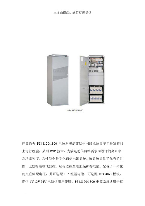
产品简介PS48120/1800电源系统是艾默生网络能源集多年开发和网上运行经验,采用DSP技术,为满足通信网络需求而设计的高可靠、高功率密度、高性能全数字化通信电源系统。
该系统提供了优秀的性能,比如智能电池监控,远程监控及电池保护等功能,配备了一体化的交直流配电柜,并可选配1~3组蓄电池。
可选配DPC48-3模块,提供6V,12V,24V电源供用户使用。
PS48120/1800电源系统适用于接入、传输、铁路小站、无线基站等通信网络。
系统特点全正面操作维护,适应中国国情超宽的输入电压范围(85Vac~300Vac),电网适应能力强整流模块工作环境温度范围高(-40~70 ℃),环境适应能力强整流模块采用全数字DSP控制技术,功率密度高整流模块采用全面软开关技术,额定效率高达91%以上符合UL, CE, NEBS等多种国内外标准,适用于居民区环境交流侧、直流侧、信号端全方位的防雷设计完善的蓄电池管理功能,提高电池使用寿命完善的故障保护,故障告警功能可记录200条历史告警记录,可记录10组电池测试数据无损伤热插拔,在线维护,方便快捷交流配电参数技术指标说明供电方式单相三线输入电压85V-300Vac,两路手动切换(X1型)125V-285Vac,两路自动切换(X2型)输入空开2*63A/2P输出空开1*16A/1PX2型(X1型无)直流配电参数技术指标说明额定电压-42~-58Vdc负载总容量100A电池熔丝100A*2输出分路共7路1*63A/1P, 2*32A/1P, 1*10A/1 空开1*100ANT00,1*50ANT00,1*6ANT00 熔丝整流模块:R48-1800A输入特性:输入电压:85~300Vac(85~176Vac降功率输出)输入电网频率:45~65Hz功率因数:≧0.99输出特性:输出直流电压:-42~-58V输出电流:0~33A额定效率:≧91%最大输出功率:1740W温度限功率特性45 ℃满功率输出55 ℃1450W输出65 ℃1160W输出监控模块M500D告警功能:监控单元能对系统故障进行声光报警,同时能上报到后台主机历史告警记录存储200条,并具有按键操作记录功能有8路辅助告警继电器输出告警声音、时间可控电池管理功能:自动均浮充;智能充电限流管理;负载下电;电池保护;放电测试;10组电池测试记录电池放电测试;定时放电、恒流放电、短时放电电池异常检测控制功能:整流模块开关机;整理模块限流、调压;电池组均充/浮充/测试转换;负载下电;电池保护远程接口RS232,MODEM(可选),Internet接入(可选)DC/DC变换器DPC48-3输入电压范围43VDC~60VDC输出电压标称值24V、12V、6V输出电压范围22~28.5V、11~14.2V、5.5~7.1V输出额定功率6V 12V 24V0W0W 0W30W100W 100W60W200W 200W注意:1、三种电压类型可任意组合2、每种电压类型只能选一种功率机械参数部件外形尺寸高*宽*深(mm) 重量监控模块87*85*287 0.8kg整流模块87.9*85.3*272 2.0kg机柜2000*600*600 ≦110kg(X1型)2000*600*600≦120kg(X2型)。
艾默生通信电源PS48120-1800中文胶片200611

PS48300/1800系统典型配置 PS48300/1800
项目
系统 整流模块 监控模块
型号
PS48120 R48-1800 M500D
数量
1 2~4 1 视客户需要选择
附注
整流模块 ---R48-1800 ---R48-1800
- CE and UL marked - 宽输入电压范围: 85 – 300 Vac - 输入频率范围: 45~65Hz - 宽工作温度范围: -40°C to +70°C (+45°C 以上降额输出) - 相对湿度 : ≤90%RH - 海拔高度 : ≤2000m - 效率 : 91% - 功率因数 : 0.99 - MTBF : >=12 Years - 重量: 2.0 kg
PS48120/1800一体化电源系统 PS48120/1800
PS48120/1800 一体化电源系统是艾默 生网络能源集多年开发和网上运行经验, 采用DSP技术,为满足3G网络需求而设计 高可靠、高功率密度、高性能、全数字化 的通信电源系统。
PS48120/1800 电源系统特点
最大可以提供6.96kW 全正面操作,方便安装和维护 宽输入电压范围:85Vac-300Vac 整流模块宽工作温度范围:-40° C ~ 70°C 整流模块采用了DSP控制技术,有高功率密度 完善的蓄电池管理功能,实现电池保护 完善的交直流、信号防雷 整流模块和监控模块可以无损伤热插拔,在线维护,方便快捷 符合CE、UL、NEBS等多种国内外标准,适用于居民区环境
R48-1800
监控模块---M500D ---M500D
通过CAN可以管理最多48个模 块 完善的蓄电池管理 具有PLC功能 告警和告警记录功能,最多可记 录200条故障信息 8组告警干接点输出 提供RS232/Modem通信方式 多语言操作界面
Sistema de UPS SmartOnline SU2200RTXL2Ua 商品说明说明书
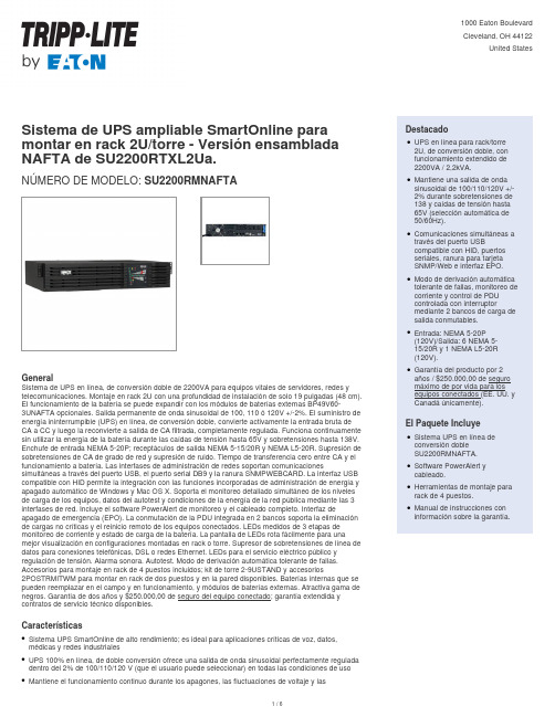
montar en rack 2U/torre - Versión ensamblada NAFTA de SU2200RTXL2Ua.SU2200RMNAFTANÚMERO DE MODELO:GeneralSistema de UPS en línea, de conversión doble de 2200VA para equipos vitales de servidores, redes y telecomunicaciones. Montaje en rack 2U con una profundidad de instalación de solo 19 pulgadas (48 cm). El funcionamiento de la batería se puede expandir con los módulos de baterías externas BP49V60-3UNAFTA opcionales. Salida permanente de onda sinusoidal de 100, 110 ó 120V +/-2%. El suministro de energía ininterrumpible (UPS) en línea, de conversión doble, convierte activamente la entrada bruta de CA a CC y luego la reconvierte a salida de CA filtrada, completamente regulada. Funciona continuamente sin utilizar la energía de la batería durante las caídas de tensión hasta 65V y sobretensiones hasta 138V. Enchufe de entrada NEMA 5-20P; receptáculos de salida NEMA 5-15/20R y NEMA L5-20R. Supresión de sobretensiones de CA de grado de red y supresión de ruido. Tiempo de transferencia cero entre CA y el funcionamiento a batería. Las interfases de administración de redes soportan comunicacionessimultáneas a través del puerto USB, el puerto serial DB9 y la ranura SNMPWEBCARD. La interfaz USB compatible con HID permite la integración con las funciones incorporadas de administración de energía y apagado automático de Windows y Mac OS X. Soporta el monitoreo detallado simultáneo de los niveles de carga de los equipos, datos del autotest y condiciones de la energía de la red pública mediante las 3 interfases de red. Incluye el software PowerAlert de monitoreo y el cableado completo. Interfaz de apagado de emergencia (EPO). La conmutación de la PDU integrada en 2 bancos soporta la eliminación de cargas no críticas y el reinicio remoto de los equipos conectados. LEDs medidos de 3 etapas de monitoreo de corriente y estado de carga de la batería. La pantalla de LEDs rota fácilmente para una mejor visualización en configuraciones montadas en rack o torre. Supresor de sobretensiones de línea de datos para conexiones telefónicas, DSL o redes Ethernet. LEDs para el servicio eléctrico público y regulación de tensión. Alarma sonora. Autotest. Modo de derivación automática tolerante de fallas. Accesorios para montaje en rack de 4 puestos incluidos; kit de torre 2-9USTAND y accesorios2POSTRMITWM para montar en rack de dos puestos y en la pared disponibles. Baterías internas que se pueden reemplazar en el campo y en funcionamiento, y módulos de baterías externas. Atractiva gama de negros. Garantía de dos años y $250.000,00 de seguro del equipo conectado; garantía extendida y contratos de servicio técnico disponibles.CaracterísticasSistema UPS SmartOnline de alto rendimiento; es ideal para aplicaciones críticas de voz, datos,qmédicas y redes industrialesUPS 100% en línea, de doble conversión ofrece una salida de onda sinusoidal perfectamente regulada qdentro del 2% de 100/110/120 V (que el usuario puede seleccionar) en todas las condiciones de uso Mantiene el funcionamiento continuo durante los apagones, las fluctuaciones de voltaje y lasqEspecificacionessobretensiones con cero tiempo de transferencia .Elimina la distorsión armónica, los impulsos eléctricos rápidos, las fluctuaciones de frecuencia y otros problemas eléctricos difíciles de resolver que no solucionan otros tipos de UPS.qCorrige las condiciones de voltaje de la línea desde sólo 65 V y hasta 138 V a valores seleccionables de 100/110/120 V (+/-2%)qEl conjunto de baterías internas estándar ofrece 18 minutos de funcionamiento extendido con carga media (800 W) y 6 minutos a plena carga (1600 W).qEl módulo de baterías externas opcional BP48V60-3UNAFTA prolonga la autonomía a 132 minutos en media carga (800W) y a 61 minutos a plena carga (1600W/compatible con diversos módulos)qEl factor de forma compacto para instalación en rack se instala en sólo dos espacios de rack (2U) con sólo una profundidad de instalación máxima de 19 pulgadasqSe envía con todos los accesorios para la instalación en rack de 4 postes q El 2POSTRMKITWM opcional permite la instalación en rack de 2 postes o paredq El accesorio 2-9USTAND opcional permite la colocación en torre vertical de tamaño reducido.q Derivación automática tolerante a fallas mantiene una salida continua de energía de la red pública a los equipos conectados, incluso en casos en que el UPS presenta una falla interna y necesita mantenimiento.qLas interfases de red soportan comunicaciones simultáneas a través de los seriales USB, DB9 /cierre de contacto y de la ranura SNMPWEBCARD integradosqLa interfaz USB compatible con HID permite la integración con las funciones de administración de energía y cierre automático de Windows y Mac OS X incorporadas.qEl software de monitoreo para UPS PowerAlert admite el cierre seguro sin supervisión, el monitoreo y control mediante servidores locales conectados, además de cualquier cantidad de servidores adicionales sobre IP.qLa interfaz del UPS soporta batería en uso, batería baja, restauración de la potencia, voltaje CA, voltaje CD, monitoreo de la corriente de salida, corriente de la carga de batería, capacidad de la batería,frecuencia de línea de CA, apagado programado del inversor, activación de la autoprueba y control de potencia de la salida de los bancos de carga y reinicio remoto, el ajuste de voltaje nominal del UPS y los puntos de ajuste del voltaje de la alimentación de la línea de batería del UPS.qInterfaz EPO incorporada con cableq clavija de entrada NEMA 5-20P; receptáculos de salida NEMA 5-15/20R y NEMA L5-20Rq PDU controlable integrado con 2 bancos; permite la administración remota de tomacorrientes para la eliminación de cargas no críticas o la reinicialización remota de los bancos de carga individuales (el banco uno posee dos tomacorrientes/el banco dos posee cuatro tomacorrientes)qLEDs en el panel frontal ofrecen monitoreo de la corriente e información sobre el nivel de carga de la batería.qEl UPS se envía totalmente ensamblado en total conformidad con las normas del Departamento de Transporte (DOT); no es necesario que el usuario invierta tiempo conectando las baterías internas.qSupresión de sobretensiones para una sola línea de teléfono/DSL o la red Ethernetq Garantía de 2 años del fabricante sobre el producto, $250,000 de Seguro Máximo de por Vidaq© 2023 Eaton. All Rights Reserved. Eaton is a registered trademark. All other trademarks are the property of their respective owners.。
星辰(StarTech)PEX4S553 4-口原生PCI Express RS232串行适配器卡(
4 Port Native PCI Express RS232 Serial Adapter Card with 16550 UARTProduct ID: PEX4S553The PEX4S553 4-Port Native PCI Express RS232 Serial Adapter Card with 16550 UART lets you add 4 RS232 (DB9) serial ports, using a single PCI Express expansion slot.Based on a native single-chip design, this 4-port serial adapter card allows you to harness the full capability offered by PCI Express (PCIe), while reducing the load applied to the CPU by as much as 48% over conventional bridge-chip serial cards.The RS232 Serial Adapter Card includes 4 half-height/low-profile brackets, allowing the card to be installed into almost any PC case, regardless of form factor.Backed by a Lifetime warranty and free lifetime technical support.Certifications, Reports and Compatibility Applications•POS retail applications in grocery stores, and any other retail store tocontrol keyboards, cash drawers, receipt printers, card readers / card swipes, scales, and elevated displays on poles•Bank teller workstations in either full profile or low profile versions tocontrol their serial devices such as cash drawers, card readers / card swipes, printers, keypads / pinpads, pen pads•Self-service automated machines and kiosks to control serial devices such as scales, touchscreens, magnetic card readers, bar codescanners, receipt printers, label printers•Standard ATM automated teller machines to control keypads, receipt printer, card readers / card swipes, touchscreen LCD's, cameracontrol, etc.•Used to control multiple surveillance / security cameras in a parking structure, office building, etc.Features•Four high speed RS232 serial ports, with support for data transfer rates up to 128000bps•256-byte deep FIFO per transmitter and receiver•Native single-Chip, single lane PCI Express•Includes half-height/low profile mounting brackets•Built-in 16C450/550 compatible UART•Compliant with PCI Express Base Specification 1.1Warranty LifetimeHardware Bus Type PCI ExpressCard Type Standard Profile (LP bracket incl.)Chipset ID ASIX - MCS9904CV-AAInterface SerialPort Style Integrated on CardPorts4Performance Data Bits5, 6, 7, 8FIFO256 bytesMax Baud Rate128 KbpsMTBF26,280 HoursParity5, 6, 7, 8Serial Protocol RS-232Connector(s)Connector Type(s) 1 - PCI Express x1 MaleExternal Ports 4 - DB-9 (9 pin, D-Sub) MaleSoftware Microsoft WHQL Certified YesOS Compatibility Windows® DOS, 95, 98SE, 2000, CE 5.0/6.0, EmbeddedSystem 2009, POS Ready 2009, XP Embedded, XP, Vista, 7,8, 8.1, 10Windows Server® 2003, 2008 R2, 2012, 2012 R2, 2016,2019Mac OS® 10.4 to 10.10Linux 3.5.x to 4.11.x LTS Versions OnlyEnvironmental Humidity5~85% RHOperating Temperature0°C to 50°C (32°F to 122°F)Storage Temperature-20°C to 60°C (4°F to 140°F)Color GreenPhysicalCharacteristicsProduct Height0.7 in [1.9 cm]Product Length 4.7 in [12 cm]Product Width 5.1 in [13 cm]Weight of Product 2.6 oz [74 g]PackagingPackage Height 1.2 in [30 mm]InformationPackage Length 6.7 in [17 cm]Package Width 5.6 in [14.1 cm]Shipping (Package) Weight8.1 oz [230 g]What's in the Box Included in Package 1 - 4 Port PCI-Express RS-232 Serial Card1 - Bracket with2 DB9 male ports4 - Low Profile Brackets1 - Driver CD1 - Instruction ManualProduct appearance and specifications are subject to change without notice.。
RT8120
z System (Graphic, MB) with 5V or 12V Power z Graphic Cards (AGP 8X, 4X, PCI Express*16) z 3.3V to 12V Input DC/DC Regulators z Low Voltage Distributed Power Supplies
1
RT8120
Marking Information
RT8120xGS
RT8120x GSYMDNN
RT8120xGS : Product Number YMDNN : Date Code
RT8120xGSP
RT8120x GSPYMDNN
RT8120xGSP : Product Number YMDNN : Date Code
Ordering Information
RT8120
Package Type S : SOP-8 SP : SOP-8 (Exposed-Pad-Option 1)
Lead Plating System G : Green (Halogen Free and Pb Free) Z : ECO (Ecological Element with
RT8120xZS
RT8120x ZSYMDNN
RT8120xZS : Product Number YMDNN : Date Code
RT8120xZSP
RT8120x ZSPYMDNN
RT8120xZSP : Product Number YMDNN : Date Code
Typical Application Circuit
Technology for Gate Drivers z Fixed Frequency 300kHz z Internal Soft-Start z Over Current Protection by Sensing MOSFET RDS(ON) z Enable/Shutdown Control z Drives Two N-MOSFETs z Full Duty Cycle : 0% to 85% z Fast Transient Response z Voltage Mode PWM Control with External
PS48120-1800用户手册
危险 规和规范。只有具有高压、交流电作业资格的人员才能进行各项高压操作。
工具
警告 在进行高压、交流电各种操作时,必需使用专用工具,不得使用普通或自行携带的工具。
雷雨
危险 严禁在雷雨天气下进行高压、交流电,及铁塔、桅杆作业。
2.1 安全规定.................................................................................................................................................................................5 2.2 安装准备.................................................................................................................................................................................5 2.3 机械安装.................................................................................................................................................................................6
艾默生网络能源有限公司 地址:深圳市南山区科技工业园科发路一号 邮编:518057 公司网址: 客户服务热线:4008876510 E-mail: service@
Startech PEX2S553S 2 Port 工业级PCIe RS232串口卡,带电源输出和E
DE: Bedienungsanleitung - FR: Guide de l'utilisateur - ES: Guía del usuario - IT: Guida per l'uso - NL: Gebruiksaanwijzing - PT:Guia do usuário - PEX2S553S2 Port Industrial PCIe RS232 Serial Card with Power Output and ESD Protection*actual product may vary from photosFCC Compliance StatementThis equipment has been tested and found to comply with the limits for a Class B digital device, pursuant to part 15 of the FCC Rules. These limits are designed to provide reasonable protection against harmful interference in a residential installation. This equipment generates, uses and can radiate radio frequency energy and, if not installed and used in accordance with the instructions, may cause harmful interference to radio communications. However, there is no guarantee that interference will not occur in a particular installation. If this equipment does cause harmful interference to radio or television reception, which can be determined by turning the equipment off and on, the user is encouraged to try to correct the interference by one or more of the following measures:• Reorient or relocate the receiving antenna.• Increase the separation between the equipment and receiver.• Connect the equipment into an outlet on a circuit different from that to which the receiver is connected.• Consult the dealer or an experienced radio/TV technician for help.Use of Trademarks, Registered Trademarks, and other Protected Names and Symbols This manual may make reference to trademarks, registered trademarks, and other protected names and/or symbols of third-party companies not related in any way to . Where they occur these references are for illustrative purposes only and do not represent an endorsement of a product or service by , or an endorsement of the product(s) to which this manual applies by the third-party company in question. Regardless of any direct acknowledgement elsewhere in the body of this document, hereby acknowledges that all trademarks, registered trademarks, service marks, and other protected names and/or symbols contained in this manual and related documents are the property of their respective holders.Table of ContentsIntroduction (1)Packaging Contents (1)System Requirements (1)Product Overview (1)Jumper Settings (2)RS232 Pinout (2)Installation (3)Hardware Installation (3)Driver Installation (4)Verifying Installation (5)Specifications (6)Technical Support (7)Warranty Information (7)Product OverviewPower over Serial Enable/Disable (Port 2)DB9 Connector (Port 2)Power over Serial Enable/Disable (Port 1)DB9 Connector (Port 1)IntroductionThe PEX2S553S 2-Port PCI Express Serial Card lets you add two ESD-Protected (15kV) RS232 ports, with 5V or 12V selectable power output through a PCI Express slot.Packaging Contents• 1x Serial Card • 2x Low Profile Brackets • 1x Driver CD • 1x Instruction ManualSystem Requirements• Available PCI Express slot• Available LP4 power connector (if additional power is required)Jumper SettingsPower over serial Enable/Disable (per-port):Each port has 2 sets of jumper pins (labeled above) that can be configured to provide power over Pin 1 and/or Pin 9, or neither.RS232 PinoutNOTE: Pin 1 and/or 9 of the DB9 connector will output DC power if the corresponding jumper was enabled.DCD (Data Carrier Detect): No power sent over Pin 15V: DC5V, from LP4 (LP4 power connection required)12V: DC12V, from LP4 (LP4 power connection required)RI (Ring Indicator): No power sent over Pin 95V: DC5V, from LP4 (LP4 power connection required)12V: DC12V, from LP4 (LP4 powerconnection required)InstallationWARNING! PCI Express cards, like all computer equipment, can be severely damaged by static electricity. Be sure that you are properly grounded before opening your computer case or touching your PCI card. recommends that you wear an anti-static strap when installing any computer component. If an anti-static strap is unavailable, discharge yourself of any static electricity build-up by touching a large grounded metal surface (such as the computer case) for several seconds. Also be careful to handle the card by its edges and not the gold connectors. Hardware Installation1. Turn your computer off and any peripherals connected to the computer (i.e. Printers, external hard drives, etc.). Unplug the power cable from the rear of the power supply on the back of the computer and disconnect all peripheral devices.2. Remove the cover from the computer case. Refer to documentation for your computer system for details.3. Locate an open PCI Express slot and remove the metal cover plate on the rear of the computer case.4. Gently insert the card into the open PCI Express slot and fasten the card’s bracket to the rear of the case.NOTE: If installing the card into a low profile system, replacing the pre-installed standard profile bracket with the included low profile bracket may be necessary. 5. (Optional) Connect an available LP4 power connection from your system power supply to the card if additional power is required.6. Place the cover back onto the computer case.7. Insert the power cable into the socket on the power supply and reconnect all other peripherals removed in Step 1.Driver InstallationWindows1. Upon starting Windows, if the Found New Hardware wizard appears on the screen, cancel/close the window and insert the included Driver CD into the computer’s CD/ DVD drive.2. Open the Device Manager by right-clicking on Computer, and then select Manage. In the new Computer Management window, select Device Manager from the left window panel (For Windows 8, open the Control Panel and selectDevice Manager).3. Expand the Multi-port serial adapters section and right-click on the newly detected “Exar’s 2-Port UART PCI-Express Card” device4. Select Update Driver Software, which will start the Update Driver Software Wizard.5. On the How do you want to search for driver software? window, click Browse my computer for driver software.6. Click the Browse button, and navigate to your CD/DVD drive.7. Select the appropriate 32 or 64-bit OS folder for the system you are using and click Next to install the drivers.Verifying Installation1. Open the Device Manager by right-clicking on Computer, and then select Manage. In the new Computer Management window, select Device Manager from the left window panel (For Windows 8, open the Control Panel and selectDevice Manager).2. Expand the Multifunction Adapters and Ports (COM & LPT) sections. On a successful install, you should see 1 Exar’s 2-Port UART PCI-Express Card device in the Multifunction Adapters section, and 2 Exar’s Communications Port (COMx) devices installed with no exclamation points or question marks.SpecificationsTechnical Support’s lifetime technical support is an integral part of our commitment to provide industry-leading solutions. If you ever need help with your product, visit /support and access our comprehensive selection of online tools, documentation, and downloads.For the latest drivers/software, please visit /downloads Warranty InformationThis product is backed by a lifetime warranty.In addition, warrants its products against defects in materials and workmanship for the periods noted, following the initial date of purchase. During this period, the products may be returned for repair, or replacement with equivalent products at our discretion. The warranty covers parts and labor costs only. does not warrant its products from defects or damages arising from misuse, abuse, alteration, or normal wear and tear.Limitation of LiabilityIn no event shall the liability of Ltd. and USA LLP (or their officers, directors, employees or agents) for any damages (whether direct or indirect, special, punitive, incidental, consequential, or otherwise), loss of profits, loss of business, or any pecuniary loss, arising out of or related to the use of the product exceed the actual price paid for the product. Some states do not allow the exclusion or limitation of incidental or consequential damages. If such laws apply, the limitations or exclusions contained in this statement may not apply to you.Hard-to-find made easy. At , that isn’t a slogan. It’s a promise. is your one-stop source for every connectivity part you need. From the latest technology to legacy products — and all the parts that bridge the old and new — we can help you find the parts that connect your solutions.We make it easy to locate the parts, and we quickly deliver them wherever they need to go. Just talk to one of our tech advisors or visit our website. You’ll be connected to the products you need in no time.Visit for complete information on all products and to access exclusive resources and time-saving tools. is an ISO 9001 Registered manufacturer of connectivity and technology parts. was founded in 1985 and has operations in the U nited States, Canada, the United Kingdom and Taiwan servicing a worldwide market.。
- 1、下载文档前请自行甄别文档内容的完整性,平台不提供额外的编辑、内容补充、找答案等附加服务。
- 2、"仅部分预览"的文档,不可在线预览部分如存在完整性等问题,可反馈申请退款(可完整预览的文档不适用该条件!)。
- 3、如文档侵犯您的权益,请联系客服反馈,我们会尽快为您处理(人工客服工作时间:9:00-18:30)。
移动视频转码
MPEG4/CIF => H.264 /CIF 15fps
高清视频会议
H.264/720p 30fps x 4 个参与者会议
注意:准确的性能取决于很多因素,包括准确的编解码器混合、使用模式、甚至主机加载。这些数字是根据目前的软件版 本估计的并作为常用应用潜在性能的指导。
* 性能数字基于 Vocallo MGW 1.9 版
4 个 DSP
2560 个信道 1716 个信道 128 个信道 2 个网桥
8 个 DSP
5120 个信道 3432 个信道 256 个信道 4 个网桥
12 个 DSP
7680 个信道 5148 个信道 384 个信道 6 个网桥
无线语音网关:
G.711(20ms) <=> AMR NB(20ms)
● 基于 DSP 的解决方案,实现最佳功率/性能
– –
● 包括综合语音和视频处理固件 ● 2 个可选 GbE RJ45 接口用作直接流终端,备可选 NAT 功能
● 在合适的运营商级机架式机箱中,设计用于 NEBS/ETSI
2
Octasic Vocallo 技术简介
● 高性能 OCT2224M 数字信号处理器
19
PCIE 的价值定位
● 在 2U 机架式服务器配置中部署了很多新的网络应用 ● 扩展时,增加 PCIE-8120 可以避免购买更多服务器
在会话边界控制器添加语音处理功能
Price $35,000 $30,000 $25,000 $20,000 $15,000 $10,000 $5,000 $0 0 5,000 10,000 Ports 15,000 20,000
媒体处理 API 基本上是 Octasic Vocallo API —— 用 于控制和管理 DSP 功能
艾默生加速卡支持实用程序 提供配置和监控特性(如: 温度传感器)的途径
14
PCIE-8120 的选项
标准选项为 4 个、8 个 和 12 个 DSP。根据个别环境或个别容量 需求的热研究,可以进一步优化 DSP 的数量
8
8 12 12
39W
39W 55W 55W
46W
46W 65W 65W
只有“V”版本启用了视频处 理。
15
PCIE-8120 的性能和可扩展性
3 个版本有助于更好地满足性能* 和应用需求: 应用
标准语音网关:
G.711 (20ms) <=> G.729AB (20ms)
6
视频编解码器
● MPEG-2
–
用于广播:DVD、数字电视。效率不高
● H.263
–
专为提高低比特率应用(如:可视电话和视频会议等)的 视频质量而开发
● MPEG-4 第 2 部分
–
类似于 H.263
● MPEG-4 第 10 部分/H.264/AVC
–
在移动、数字电视和 IP 电视领域非常普及的新标准。目前 的主要兴趣所在
● 转速率
–
–
例如:从 15 fps 变为 30 fps
更改图像的尺寸 将视频流加在一起或者用一个视频流覆盖另一个 用于画中画或视频会议
● 调整尺寸
–
● 混合
– –
所有的视频操作都是在原始视频上进行的,所以需要有一个解码和 一个编码阶段
9
示例:网络/内容优化应用的点播转码
内容存储在: 内容发送到:
TD M
电话网络
蜂窝网络
IP 网络
12
会话边界控制器:全 IP 到 IP
核心网
接入网关(GW) 基础架构 会话边界控制器
移动交换中心(MSC)
核心网
SIP 中继
服务提供商
企业 会话边界控制器
13
PCIE-8120 的软件架构
最初支持的主机操作系统是 RedHat Enterprise Linux 6.3。
提升系统的媒体处理性能 网络研讨会
2013 年 7 月
PCIE-8120(“Citadelle”)简介
● 用于高密度语音和视频处理的 PCI Express 媒体处理加速卡
–
全高度、全长度、单槽位 PCIe 卡, PCIe x4 接口 多达 12 个 Octasic DSP, 提供超过 7600 个 G.711 G.729 之间的转码以及 6 个 HD 720p 的四方视频 会议
语音应用:信道数量多! 视频应用:减荷是关键!
16
软件功能 - 包括全部
17
PCIE-8120 的关键应用
媒体网关/媒体服务器/媒
体资源功能
图像处理
– 一般为自定义 DSP 算
交互式语音/视频响应 移动视频会议/视频转码
法和出入加速卡时的超 高数据流速
移动网络优化
会话边界控制器的转码
槽位功率受限(取决于客户)的 系统的外部电源连接器选项
提供硬件(FPGA)网络地址翻 译支持的外部 GbE 终止功能。 不适用于 –N 版本
DSP 数 量 PCI-8120-A12-N PCI-8120-V12-N PCI-8120-A04 PCI-8120-V04 12 12 4 4
估计的最 大功率 @ 35C
● PCIE-8120 产品细节
– MyComputing: MyDocuments > Products > PCIe –
● Octasic DSP
– 参见
22
23
– –
每颗芯片上集成 24 个 DSP 核 异步设计 = 非常低的功率(或非常高的 性能/瓦)
● 我们的单板将配备优化的 DSP 固件和
软件编程环境(Vocallo MGW)
– –
● 语音和视频处理能力都可用
语音包括所有无线和有线编解码器以及 网关封装、回波控制等 视频包括最高可达 1080p 的 H.263、 MPEG4、H.264 以及混合和重叠
广播视频
监控
18
成功案例?
●
客户 A:向会话边界控制器添加语音 编解码
– –
●
客户 B:向现有基于 x86 的 IMS 媒体服务器添加高清视频
– –
使用 PCIE-8120 在无线和有线网络 编解码器之间转换 使用运营商级机架式服务器的 NEBS 应用
使用 PCIE-8120 来支持 720p 视 频会议和消息,不影响性能 在 HP DL380p 中每个机箱使用 2 块加速卡的数据中心应用
添加媒体处理加 速卡
没有添加媒体处理加 速卡
Server + PCIE Price Server Price
成本
20
对比商用 HMP 解决方案
向应用添加多达 15000 个 G.729A 压缩语音端口 所需额外服务器数量 使用 PCIE-8120 0 2 块 PCIE-8120 即可实现 使用主机媒体处理 8 - 12 取决于 HMP 解决方案(例如 Vendor X HMP4,每个服务器上 1200 个 G.729 端口 @G.729) 平均 10 x 400W = 4000W 10U (假设为 10 x 1U 服务器) 10 x $3200 = $32,000 每个端口低至 $1 时需要 $15,000, 但可能更多
● H.265
–
刚刚批准的新标准,即将进入每个人的视野
7
移动/小屏幕分辨率
CIF:352x288
标准清晰电视:720x486 (NTSC)
QCIF:176x144 SQCIF:88x72
即使移动设备也逐渐转向高清屏幕
8
视频处理术语
● 转码
–
–
在两个编解码器之间转换
例如:从 H.263 到 H.264 的转换 改变视频流的速率
53W 53W 23W 23W
估计的最 大功率 @ NEBS
63W 63W 27W 27W
外部 GbE 端口
语音 SW 支持
视频 SW 支持
将先发布 -N 版本
PCI-8120-A08
PCI-8120-V08 PCI-8120-A12 PCI-8120-V12
新
4
适合媒体处理的场景
媒体服务器和视 频流媒体服务器
公共网络
接入网关(GW)
核心网
核心网
企业语音和视频网关
会话边界控制器(SBC)
有线和无线 视频和语音网关
高清视频会议 MCU
5
压缩视频
4-10 Mbps 编码视频 MPEG2 NTSC:标准电视 100-150 Mbps 原始视频
10-40 Mbps 编码视频 H.264 1080p 高清视频 750 Mbps 原始视频
互联网
IPTV 机顶盒
CDN
手机
VOD 服务器
4G 笔记本电脑
10
视频会议基本原理
多点会议单元
MCU
软件电话或软件客户端
个人/执行装置或可视电话
多编解码器或多屏幕系统
房间系统或单编解码器系统
11
媒体网关
媒体网关
1. 回波抵消 DE/MUX I/F 2. 语音压缩 3. 打包 MAC 报文 I/F
3
基于 DSP 的艾默生可扩展媒体处理产品
ATCA-8320
– – 每个单槽位刀片上 5 至 24 个 DSP 网关位于支持直接 I/O 和 TDM 可选件的刀片式架 构上
PCIE-8120
– – – 每个单槽位卡上 4 至 12 个 DSP 外部 RJ45 GbE 访问选项 插入合适的机箱,适用于 NEBS