WG-827型商务网关说明书
ICP DAS USA 产品说明 - 工业级 Modbus 网关说明书

Industrial Modbus GatewayModbus is a standard industrial communication protocol, and is now the most commonly available means of connecting industrial electronic devices. Modbus allows for communication between many devices connected to the same RS-485 network, for example, a system that measures temperature and humidity and communicates the results to a computer. Modbus is often used to connect a supervisory computer with a remote terminal unit (RTU) in supervisory control and data acquisition (SCADA) systems.There are different version of the Modbus protocol for serial and Ethernet communication. Modbus RTU and ASCII are used in serial communication that makes use of ASCII characters for protocol communication. Modbus RTU is the most common implementation available for Modbus. Modbus TCP is used for communication over TCP/IP networks, connecting over port 502.The tGW-700 is a Modbus TCP to RTU/ASCII gateway that enables a Modbus/TCP host to communicate with serial Modbus RTU/ASCII devices through an Ethernet network, and eliminates the cable length limitation of legacy serial communication devices. The module can be used to create a pair-connection application (as well as serial-bridge or serial-tunnel application), and can then route data over TCP/IP between two serial Modbus RTU/ASCII devices, which is useful when connecting mainframe computers, servers or other serial devices that use Modbus RTU/ASCII protocols and do not themselves have Ethernet capability.The new read-cache function is used to store previous requests and responses in the memory buffer of the tGW-700 module. When other HMI/SCADA master controllers send the same requests to the same RTU slave device, the cached response is returned immediately. This feature dramatically reduces the loading on the RS-485 bus communication, ensures faster TCP responses, and improves the stability of the entire system.DHCP minimizes configuration errors caused by manual IP address configuration, such as address conflicts caused by the assignment of an IP address to more than one computer or device at the same time. The tGW-700 module supports the DHCP client function, which allows it to easily obtain the necessary TCP/IP configuration information from a DHCP server. The module also contains a UDP responder that transmits its IP address information in response to a UDP search from the eSearch utility, making local management more efficient.The tGW-700 module also features a powerful 32-bit MCU to enable efficient handling of network traffic, and also has a built-in web server that provides an intuitive web management interface that allows users to modify the configuration of the module, including theDHCP/Static IP, the gateway/mask settings and the serial port settings.The module contains a dual watchdog, including a CPU watchdog (for hardware functions) and a host watchdog (for software functions). The CPU watchdog automatically resets the CPU if the built-in firmware is operating abnormally, while the host watchdog automatically resets the CPU if there is no communication between the module and the host (PC or PLC) for a predefined period of time (system timeout). The dual watchdog is an important feature that ensures the module operates continuously, even in harsh environments. In addition, the tGW-700 series (for i version) also adds 3000 VDC isolation and +/-4 kV ESD protection component that diverts the potentially damaging charge away from sensitive circuit to protects the module and equipment from the sudden and momentary electric current.The tGW-700 module offers true IEEE 802.3af-compliant (classification, Class 1) Power over Ethernet (PoE) functionality using a standard category 5 Ethernet cable to receive power from a PoE switch such as the NS-205PSE. If there is no PoE switch on site, the module will also accept power input from a DC adapter. The tGW-700 module is designed for ultra-low power consumption, reducing hidden costs from increasing fuel and electricity prices, especially when you have a large number of modules installed. Reducing the amount of electricity consumed by choosing energy-efficient equipment can have a positive impact on maintaining a green environment.The module is equipped with a male DB-9 or a removable terminal block connector to allow easy wiring. Based on an amazing tiny form-factor, the tGW-700 achieves maximum space savings that allows it to be easily installed anywhere, even directly embedded into a machine. It also supports automatic RS-485 direction control when sending and receiving data, thereby improving the stability of the RS-485 communication.tGW-700 series offers different combination of number of ports to select, including RS-232, RS-422, and RS-485 for your applications.If you have other industrial communication requirements or have questions, we can certainly help you to choose the best solution. Please call our technical support team at (310) 517-9888 X102。
中国电信 商务领航定 制网关1-1 客户使用手册

商务领航定制网关 1-1 客户使用手册 z 预先设置好的无线网络名称(SSID)为“ChinaNet-XXXX”,名称
的后四位“XXXX”为 4 位随机字符或数字。具体的 SSID 名称和无 线网络接入密码详见本产品的外壳标签。 z 可以修改无线网络名称(SSID)的后四位,具体修改步骤请参见 第 6 章无线组网部分。 配置无线客户端软件的步骤如下(以使用 Windows 自带的无线连接工具为例): 步骤 1 如下图所示,点击【开始】>【设置】>【网络连接】:
8 快速故障定位 ........................................................................................ 14 9 技术规格 ................................................................................................ 16
第4页
编号
名称
(WPS)
(7)
USB 指示灯 (USB)
后面板
商务领航定制网关 1-1 客户使用手册
状态 闪烁 常亮
含义/功能 按下按钮时闪烁(约 2 分钟) 已连接到 USB 设备
编号 (1) (2) (3)
(4) (5) (6)
名称 Power Line
Reset
固定交换口 LAN1~4 WPS WLAN
常亮
以太网指示灯
不亮
(LAN4~LAN1) 闪烁
常亮
无线指示灯
不亮
(WLAN)
闪烁
常亮
WPS 指示灯
常亮
含义/功能 表示电源没有接通 表示电源接通 表示 DSL 线路断开表示 DSL 链路正在同步 表示 DSL 链路同步完成 表示网络没有连接 有数据传输 表示网络已连接 表示链路没有连通 表示有数据收发 表示链路已经连通 表示链路没有连通 有数据传输 表示链路已经连通 开启后常亮
WG-315商务网关2.6版使用说明书
2 术语定义 ............................................................................... 8
AT-MQTT 网关用户指南说明书

MQTT - Gateway(Order Code: AT-MQTT Gateway)Contact Us[A] 60 – Street No.1 – Tân Thành Ward – Tân Phú Dist. – HCM City – Vietnam [T] (+84)(8).3842 5226[E] **************.vn[W] Benefits and Main Features:Very easy to configurePower Supply 5V DC and 2ATemperature range: -40°C/+85°C (-40°F/+185°F)Table of ContentsINTRODUCTION (2)CONFIGURATION (4)Prerequisites............................................................................................................................................... Gateway configuration...............................................................................................................................Step 1 ......................................................................................................................................................Step 2 : (6)Step 3 : (7)Step 4 : (8)Step 5 : (8)Subcribe and publish the MQTT topic associated with each Tag. (10)INTRODUCTIONThe AT-MQTT Gateway is Modbus RTU master to MQTT Converter.It allows to publish the data read from Modbus Slaves into MQTT Server.The gateway allows fast and easy access to IoT world and is compatible with IoT Servers that support MQTT protocol.Example of connection:AT- MQTT-GatewayCONFIGURATIONPrerequisitesBefore configuring communication parameters via Web Interface, you need to connect the gateway to internet network by wire or Wi-Fi connection. For changing IP of the gateway, kindly search on “how to change raspberry IP”.Gateway configurationYou need to access to web Interface (the server runs on your gateway) in order to perform the following:Define the parameter of MQTT.Define the parameter of Modbus RTU channel.Define which Modbus memory addresses sent to MQTT serverChange your account and password.Reboot the gateway to update your configuration.Step 1: Access Web interface with url: “IP:9000”, if you use default LAN IP, the url is “192.168.1.100:9000”.You are prompted to enter username and password. The default user name is “admin”,the default password is “admin”. Then click Login button and you will be logged into web interface:The page is divided in different sections in order to define the different parameters of the gateway:∙ModbusRTUCommunication∙MQTTCommunication∙Tags∙AccountStep 2:Define the parameter of Modbus channel.“Port Name”: the port name to use (/dev/tty/USB0)“Baud Rate”: the baud rate of the serial line.“Databits”: the data bits of the serial line.“Parity”: the parity of the serial line.“Stopbits”: the stop bits of the serial line.“Response Timeout”: the time out of the serial line.“Period”: the period is the Cycle of Modbus master-slave query-response.Click “Apply” to update your configuration.Step 3:Define the parameter of MQTTThe section is used to define the main parameters of MQTT. Meaning of each row:“MqttClient ID”: Mac address of your gateway and cannot be changed.“Server Url”: Url or the IP Address of the defined MQTT server.“Server Port”: the port used for defined MQTT communication.“Username”: the username for the connection to MQTT server.“Password”: the password for the connection to the MQTT server.“Clean Section”: if set to “True”, the last MQTT message is deleted by the server and the client in case of missing ACK. If it is set to “false”, theServer and the client hold the last MQTT messages and , in case ofincorrect disconnection or missing ACK, they try to send again since allthe ACK messages are exchanged correctly (valid only for Qos 1 and QoS2).“Keep Alive”: the delay which the keep alive message is sent on MQTT.“Retained”: if set to “true”, the retained flag is enabled. The MQTT server will hold the last topic published.“QoS”: the Qos level.Clic k “Apply” to update your configuration.Step 4: Define which Modbus memory addresses are sent to MQTT serverMeaning of each field:“Tag Name”: the name of tag. This name must be unique.“Slave Id”: the address of the Modbus device.“Type”: the data type of the Tag. It is possible to choose between the following :o Coil Statuso Input Statuso Holding Registero Input Register“Address”: the starting address of the Tag.“Number Point”: the number of consecutive points.Click “Add” to create new tag.Click “Edit” to redefine tag.Click “Delete” to delete tag.Step 5: After completely configure the Gateway, Log out of Web Interface and Reboot your Gateway.Subscribe and publish the MQTT topic associate with each Tag.Each Tag is sent by gateway to MQTT server by publishing to a MQTT topic. These topics have name in format: Mac address/slave Id/Tag Name.For writing value to each Tag, gateway subscribes to a MQTT topic. These topics have name in the format: Write/Mac address/slave Id/Tag Name.For Example: A gateway has Mac address is “B827EB087532”. If you define a Tag named “Tag 1”and your Modbus Slave ID is “1”, The value of Tag is published to topic name : “B827EB087532/1/Tag1 “ and subscribed to topic name: “Write/ B827EB087532/1/Tag1”.Data Format is in byte array: timestamp (8 byte), Value of Tag, Status (1 byte). The Status byte means: 1 is for good connection, 0 is for bad connection.Other MQTT clients read data of Tag by subscribing to the topic that gateway has published to MQTT server.Other MQTT clients write data to Tag by publishing value to Topic that gateway has subscribed. The Value is written to Tag must be the same type with type of Tag.Change your Web Interface AccountThe default User name is “admin” and the default Password is “a dmin”. After logging in to Web interface you can change your user name and password then click “Update Account”to update your account.。
827智能定位器使用说明书

827系列智能阀门定位器随着计算机、控制、通讯、网络等技术的发展,计算机控制系统逐步从集散系统(Distributed Control Systen,DCS)走向以现场总线位基础的分布式现场总线控制系统(Fieldbus Control System,FCA)。
827智能总线阀门定位器为满足现场总线控制需要而设计,广泛应用于石化、冶金、化工、电力、轻工、炼油场合。
827智能阀门定位器让调节阀拥有大脑和灵魂!通常安装和调试阀门定位器总是花费许多时间,827智能阀门定位器使得这一切变得简单容易。
尤其是其结构紧凑无外接管路地和812系列气动执行器的连接创建了无管路的快速安装。
其独到的构造改变了多年来定位器安装的潮流。
它可以将阀位变送器集成在定位器内部,也可以将限位开关集成在定位器内部,有效地简化安装和配置。
其可以简单地安装到任何阀门上,通过友好界面,快速设置,自动标校和自动整定。
其汉化的语言界面无以伦比的性价比将引起定位器的革命性潮流。
一、概况827系列智能阀门定位器是一种新型智能阀门定位器产品,安装在气动执行器上具有丰富功能,可实现即时通讯,能直接到调节器的4-20mA输出回路上。
定位器接收标准电流信号或计算机信号,驱动气动执行机构使阀门达到给定位置。
智能定位器所有参数的调整由电子模块进行全数字化运算和操作。
定位器底座和壳罩采用能够适应工厂中恶劣环境的轻质合金制造,并进行了防腐处理,其安装连接附件均采用经过钝化处理的不锈钢材质,具有高的使用寿命。
827智能型定位器以它精确的外观设计、模块化内部结构、非常方便的调试及维护而脱颖而出。
827型智能定位器,用于气动直行程或角行程执行机构。
它的核心是微处理器CPU,所有程序的处理运算皆在此。
输入信号及位置反馈经过12位20ms采样的A/D转换器进行处理,从而保证了信号处理的精度及快速性。
CPU的供电直接取自输入信号。
操作程序包括用于自动调整参数的自整定过程及自适应控制程序,用于精确定位的优化控制操作。
gsp827中文说明书

Power Frequency Magnetic Field EN 61000-4-8 : 1993
------------------------◎ Safety
Voltage Dips/ Interrupts EN 61000-4-11: 1994
Low Voltage Equipment Directive 73/23/EEC & amended by 93/68/EEC
EN 55011: 1998 class A
EN 61000-4-2: 1995+A1:1998
Current Harmonic EN 61000-3-2: 2000 Voltage Fluctuation EN 61000-3-3: 1995
Radiated Immunity EN 61000-4-3: 1996+A1:1998 Electrical Fast Transients EN 61000-4-4: 1995
EN 61326-1: Electrical equipment for measurement, control and laboratory use –– EMC requirements (1997+A1: 1998+A2: 2001)
Conducted and Radiated Emissions Electrostatic Discharge
7. 功能目录表 ................................................................................................................................................................. 22 7.1 主要功能............................................................................................................................................................... 22 7.2 测量功能............................................................................................................................... 错误!ቤተ መጻሕፍቲ ባይዱ定义书签。 7.3 控制功能............................................................................................................................... 错误!未定义书签。 7.4 状态功能............................................................................................................................... 错误!未定义书签。
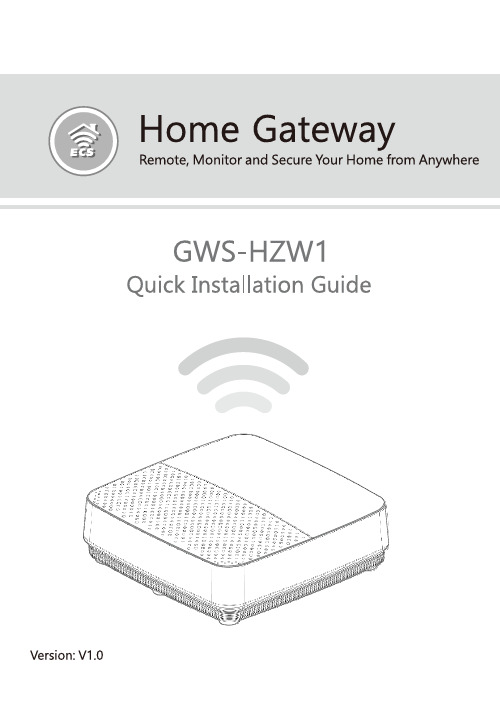
GWS-HZW1 Home Gateway 产品说明书
4
Product Feature
Connectivity LAN port, support WiFi and Bluetooth Interface DC-in port, USB port, SIM card slot, reset, LAN port, Debug client port, power switch Dimensions & Weight Dimension: 128 × 117 × 38.7 mm Weight: 335 g Environmental Conditions Operational temperature range: 0°C to +45°C (32°F to 113°F) Storage temperature range: -20°C to +60°C (-4°F to 140°F)
14
4G LTE Network Coniguration
Input the following commands. Choose one ot the following three commands(1~3) based on the corresponding LTE module. - 1. pppd call mu609 & --> Huawei ME909s 120 module
Step 2. Activate the network interface (e.g. eth0). root@WR-IntelligentDevice:~# ifconig eth0 up Step 3. If the interface matching failed, please edit /etc/ network/interfaces directly and then either restart the service or reboot the system to make the change effect.
中国普天CP_GW2100商务领航定制网关配置与维护手册v1.1

2014-6-25
中国普天 版权所有
50
虚拟局域网(VLAN)的设置和划分方法很简单,但虚拟局域网的划分又十 分的重要,在很多解决方案中都要进行虚拟局域网的划分,且虚拟局域网 有效的隔离了广播域,一定程度上阻止了一些广播病毒及风暴的发生。虚 拟局域网的划分方法总共分两步:一、添加虚拟局域网;二、划分端口。 如下:
2014-6-25 中国普天 版权所有 36
链路备份和负载分担
上行接入有三条链路,双WAN和3G,双 WAN链路做负载分担,3G为WAN链路 做备份。在两条上行链路的情况下,可 以在负载分担的基础上做相互的备份。
双WAN上行
3G ChinaNet-abcd VLAN1 VLAN2 VLAN3 VLAN4
2014-6-25 中国普天 版权所有 47
(2)防欺骗
一般欺骗的种类有欺骗网关ARP、欺骗主机ARP,针对不同的ARP欺骗,可 以采取同样的方式进行处理,防欺骗的方法有:关闭ARP学习、静态绑定、 设置端口保护、自定义发包。其中关闭ARP学习和静态绑定是最有效的防欺 骗方法,下面介绍各种方法的配置:
2014-6-25
中国普天 版权所有
34
DNS和NAT配置完成后,进行流量触发,界面显示连接成功后,即表示 3G拨号成功。
2014-6-25
中国普天 版权所有
35
产品功能配置
设备升级 基本上网功能 链路备份和负载分担 防ARP攻击功能 虚拟局域网(vlan)
安全隔离
访问限制 强制门户功能 QoS保证 搭建外部服务器功能 数据专线(VPN)的应用 管理功能
安全隔离
访问限制 强制门户功能 QoS保证 搭建外部服务器功能 数据专线(VPN)的应用 管理功能
- 1、下载文档前请自行甄别文档内容的完整性,平台不提供额外的编辑、内容补充、找答案等附加服务。
- 2、"仅部分预览"的文档,不可在线预览部分如存在完整性等问题,可反馈申请退款(可完整预览的文档不适用该条件!)。
- 3、如文档侵犯您的权益,请联系客服反馈,我们会尽快为您处理(人工客服工作时间:9:00-18:30)。
一.产品安装、使用安全说明
(一)使用注意事项
1.阅读、遵循并保留说明——操作设备之前,必须阅读并严格遵循安全说明及操作说明的所有要求。
请妥善保留本说明书,以备将来参考。
2.附件——请使用制造商推荐的附件或随产品提供的附件。
3.安装注意事项——请勿将此设备置于不稳定的台面、三脚架、支架或底座上。
防止设备由于掉落而造成的严重人身伤害及设备损坏。
请根据制造商的说明安装设备。
4.所有外接线禁止裸露,接线处和没用到的线头必须用绝缘胶布包扎,用于防止裸线意外的接触,导致设备的损坏。
5.维修——不要尝试自行维修设备。
打开或拆卸可能导致电击或其它危险。
所有维修事项均应交给专业的维修人员处理。
6.需要进行维修的损坏事项——发生以下情况时,请断开设备的交流或直流电源,然后通知专业的维修人员进行维修:-电源线或插头损坏。
-液体溅入设备或有异物落入设备。
-设备被水打湿或曝露在恶劣天气(雨、雪等)中。
-设备掉落或设备性能发生明显变化。
7.替换部件——如果需要替换部件,维修人员必须仅使用制造商指定的替换部件。
8.安全检查——维修设备之后,请让维修人员执行安全检查,确保设备能正常工作。
9.电源——仅使用标签上指明的电源类型操作设备。
如果不确定所用的电源类型请联系相关运营商
(二)安装注意事项
1.所有走线都必须套管,PVC管和镀锌管都可以,避免老鼠
咬断线路引起故障。
虽然WG-827商务网关具备了良好的防静电、
防雷击、防漏电设计,但请务必保证交流电地线连接完善,且交
流电地线真实接地。
2.建议您不要经常带电拔插接线端子;请务必拔下接线端子,
再进行相应的焊接工作。
3.对有强磁干扰的场所,应采用镀锌钢管或屏蔽线敷设并做
接地处理。
4.WG-827商务网关出厂默认IP为192.168.9.243。
计算机
在配置网关IP时,必须与网关在同一网段下,如计算机IP设置
为:192.168.9.123。
5.在配置为出厂状态下的WG-827商务网关时,必须保证在
局域网内只有一台出厂状态下的机器,以避免网络冲突。
6.完成配置网关的IP地址后,请牢记该IP地址,以避免无
法再次登录该网关。
二.产品简介
WG-827商务网关是商务系统的中间控制单元,WG-827商务
网关通过以太网配合GDC2000(6.60版本)一同使用,每台WG-827
商务网关最多可以驱动128台窗口机。
(一)系统功能特点
●采用32位高速CPU;
●支持最多驱动128台窗口机;
●采用以太网通讯技术,保证通讯的可靠性;
●内置硬件看门狗,杜绝死机;
●485通信端口具有抗雷击及浪涌保护功能;
●支持本地Web配置。
(二)主要性能指标
1.工作电源:交流198~242VAC,功率≤5W
2.工作环境:温度0℃~50℃,湿度10~85%RH
3.流水缓存笔数:26万笔
4.以太网通讯:支持10/100M自适应
5.适用于金龙卡收款机类型:SKJ-1-315、SKJ-1-415、
SKJ-1-515、SKJ-1-121、SKJ-1-221或
SKJ-1-112AS/AE
6.产品重量:2.05kg
7.外箱尺寸:330mm(长) * 222mm(宽) * 58mm(高)
(三)控制器指示灯说明
当WG-827商务网关接通电源后,电源指示灯(红灯)和所
有绿色指示灯同时点亮。
隔几秒后绿色指示灯熄灭,电源指示灯
(红灯)常亮,WG-827商务网关最多驱动POS机指示灯常亮(如
WG-827商务网关最多驱动32台POS机,则×32指示灯常亮)。
运行指示灯(绿灯)周期闪烁,表示当前系统正常运行。
当商务
系统启动营业,网关驱动POS时,发送、接收指示灯闪烁。
标号为“1”、“2”的指示灯指示的是网关连接的金龙卡收款
机类型。
“2”指示灯类型为SKJ-1-112AS/AE;“1”指示灯类型
为除SKJ-1-112AS/AE外其它类型。
三.连线、安装
把WG-827商务网关配套的电源线可靠地连接220V交流电,
并把地线真实接地。
把标号“1A-1B”或“2A-2B”
(“1A-1B”、
“2A-2B”
表示端口1或2)的端子连接到RS-485通信网络,注意RS-485
的A、B端,不要反接而影响了准确传输。
“LAN”口接网线。
说明:
RS-485通讯线采用屏蔽电缆,线材建议选用RVVP 2×0.75mm2
RJ45网线遵循ANSI/TIA/EIA-568B标准网线
注:当忘记网关IP时,可以按住“Reset”键然后开机,直到绿色指示灯闪烁。
网关会恢复出厂IP。
四.商务网关系统连网
(一) TCP/IP网络通信方式
运行GDC2000(6.60版本)软件的计算机和WG-827商务网关接入以太网,在计算机运行GDC2000(6.60版本)软件,当WG-827商务网关自动联接后,GDC2000(6.60版本)软件状态栏会显示网关就绪,则可以启动营业,网关会按照配置好的信息工作。
(二) WEB服务
在局域网内找任意一台计算机,把该台计算机IP地址改为192.168.9.123。
再在该计算机IE浏览器的地址栏内输入WG-827商务网关的IP地址(网关初始IP为192.168.9.243),将会出现网关用户登录界面,如下图所示:
在密码栏内输入正确的登录密码(WG-827商务网关初始密码为11111111)会进入WG-827商务网关的基本信息界面,在此界面中可查看WG-827商务网关基本信息,如下图所示:
在WG-827商务网关的基本信息界面点击;会
显示以下界面,可查看其系统配置信息及机器日期和时间
在网络配置页内点击,所有系统配置将恢
复到出厂设置。
WG-827商务网关会重启。
在网络配置页内点击,会安全退出网络配置页,
再次进入必须重新进行系统登录。
在网络配置页内点击,将进入网络配置修
改页面,如图
在本机IP,子网掩码,服务器IP,网关节点号以及密码修
改等栏内利用计算机键盘输入所要修改的值,点选POS类型,按
“更新设置”,则网关自动完成设置好的更改,然后网关重启。
注:
⏹一定要记住密码,以便下次登录。
⏹POS类型是指网关当前连接的金龙卡收款机类型,请
一定确认,否则RS-485无法通讯。
⏹服务器端号、网关端口号没有特殊需要可以不填,保
持网关初始值,静态密钥要与GDC2000中的节点通信
密钥相一致(如下图)。
制造商:哈尔滨新中新电子股份有限公司
生产商:哈尔滨新中新华科电子设备有限公司
地址:哈尔滨市南岗区学府路副380号。