关于轻型直流输电的部分英文文献及翻译
电气工程及自动化专业英语考试翻译课文Electric Power Systems 电力系统3.1
Section 1 Introduction 第一节介绍The modern society depends on the electricity supply more heavily than ever before.现代社会比以往任何时候对电力供应的依赖更多。
It can not be imagined what the world should be if the electricity supply were interrupted all over the world. 如果中断了世界各地的电力供应,无法想像世界会变成什么样子Electric power systems (or electric energy systems), providing electricity to the modern society, have become indispensable components of the industrial world. 电力系统(或电力能源系统),提供电力到现代社会,已成为产业界的不可缺少的组成部分。
The first complete electric power system (comprising a generator, cable, fuse, meter, and loads) was built by Thomas Edison –the historic Pearl Street Station in New York City which began operation in September 1882. 托马斯爱迪生建立了世界上第一个完整的电力系统(包括发电机,电缆,熔断器,计量,并加载)它就是位于纽约市具有历史意义的珍珠街的发电厂始于1882年9月运作。
This was a DC system consisting of a steam-engine-driven DC generator supplying power to 59 customers within an area roughly 1.5 km in radius. The load, which consisted entirely of incandescent lamps, was supplied at 110 V through an underground cable system. 这是一个直流系统,由一个蒸汽发动机驱动的直流发电机其供电面积约1.5公里至59范围内的客户。
逆变器中英文对照外文翻译文献

中英文对照外文翻译文献(文档含英文原文和中文翻译)逆变器1引言逆变器是一种电动装置,转换成直流电(DC),交流电流转换的AC(交流)可以在任何所需的电压和频率使用适当的变压器,开关,控制circuits.Solid状态逆变器有没有移动部件,用于广泛的应用范围从小型计算机开关电源,高压大型电力公司电力,运输散装直接电流应用。
逆变器通常用于提供交流电源,直流电源,如太阳能电池板或电池。
逆变器的主要有两种类型。
修改后的正弦波逆变器的输出是类似方波输出,输出变为零伏前一段时间切换积极或消极的除外。
它是简单,成本低,是大多数电子设备兼容,除敏感或专用设备,例如某些激光打印机。
一个纯正弦波逆变器产生一个近乎完美的正弦波输出(<3%的总谐波失真),本质上是相同的公用事业提供电网。
因此,它是与所有的交流电的电子设备兼容。
这是在电网领带逆变器使用的类型。
它的设计更复杂,成本5或10倍以上每单位功率电逆变器是一个高功率的电子振荡器。
它这样命名,因为早期的机械AC到DC转换器工作在反向,因而被“倒”,将直流电转换AC.The变频器执行的整流器对面功能。
2应用2.1直流电源利用率逆变器从交流电力来源,如电池,太阳能电池板,燃料电池的直流电转换成。
电力,可以在任何所需的电压,特别是它可以操作交流电源操作而设计的设备,或纠正,以产生任何所需的voltage Grid领带逆变器的直流送入分销网络的能量,因为它们产生电流交替使用相同的波形和频率分配制度提供。
他们还可以关掉一个blackout.Micro逆变器的情况下自动转换成交流电电网的电流直接从当前个别太阳能电池板。
默认情况下,他们是格领带设计。
2.2不间断电源不间断电源(UPS),电池和逆变器,交流电源,主电源不可用时使用。
当主电源恢复正常时,整流提供直流电源给电池充电。
2.3感应加热逆变器的低频交流主电源转换到更高频率的感应加热使用。
要做到这一点,首先纠正交流电源提供直流电源。
轻型HVDC和SVC简介

#:$
!"#"$%"& ’((’ ;"<"$="&
)*+, >./0?+" -./01+" 233?&?045 2331&1045
-./678 >./678
9.6:
时 >@A 发出无功 ! 向电网送无功 " ! 当 ! > !!<.5!"( 时 !""(!这时 >BA 吸收无功 !即吸收电网的无功 # 从以上分析可以得出 !>BA 控制有功 ! 和无功 " 的矢量图如图 ’$?%所示 &
为标准的正弦波 !2A 输出 & 波形上仅附着频率很高 幅值很小的纹波 ! 易于滤除 &
7
轻型 P>;A
轻型 P>;AJ 7 K的接线如图 Q 所示 &
图中阴影部分为可控制矢量 ! 和 " 的区域! 涉及 C 个象限 & 这一点充分表明 !>BA 既可送出有 功 $ 整 流 %! 也 可 吸 纳 有 功 $ 逆 变 %" 既 可 发 出 无 功 ! 也可吸收无功& 这是常规晶闸管换流器所不具备 的 & 图 7 为 传 统 )>;A 中 晶 闸 管 换 流 器 的 接 线 图 及控制原理 &
参考文献 !
E?&<*. O" T/*U"*&?6 G.V"& D/"<0&.W*<5 X.& I*0*+?0*.W .X >./0?+" B?+5 ?WO L$3&.U"O A.W0&./ .X 2A G.V"& BY50"$5 JIK6 B0.<Z,./$[ ’(((6 J’K 2WO&5 \*WO="&+6 GHI ?WO A.W0&./ .X FV. ?WO F,&"" \"U"/ P*+, G.V"& >./0?+" B.4&<" A.WU"&0" JIK6 50.<Z,./$[ S]]C6 J7K 2Z" DZ50&.W6 P*+, G.V"& D/"<0&.W*<5 P>;A ?WO B>A JEK6 B0.<Z,./$[ S]](6 JSK
变电站设计英文参考文献
变电站设计英文参考文献以下是关于变电站设计的英文参考文献列表及简介:1. "Modern Power Station Practice Vol 1: Electrical Systems and Equipment" by Central Electricity Generating Board (CEGB) - 这本书是关于电站设计的权威参考书之一,其中包含了变电站设计的细节和要求。
2. "HVDC Transmission: Power Conversion Applications in Power Systems" by K.R. Padiyar - 这本书主要涉及高压直流输电的理论和应用,而变电站通常是将交流电转换成直流电进行输电的一部分,因此这本书可以帮助设计师更好地理解变电站的工作原理。
3. "Electric Power Substations Engineering" by John D. McDonald- 这本书是变电站设计和工程的综合指南,包含了变电站的各个方面,从概述到详细设计,以及施工和运行。
4. "Transformer and Inductor Design Handbook" by Colonel Wm. T. McLyman - 压变和电感器是变电站中常见的元件,因此设计师需要了解它们的设计和制造,这本书提供了详细的指导和案例。
5. "Electric Power Distribution Handbook" by Thomas Allen Short- 这本书提供了关于配电系统的基础知识和设计方法,这对于变电站设计师来说也非常重要,因为变电站通常是配电网络的一个关键组成部分。
6. "Switchgear and Protection" by J.B Gupta - 变电站中使用的开关设备和保护系统非常关键,这本书提供了涵盖相关主题的详细信息,包括故障和过电压保护,以及开关设备的选择和维护。
电气工程及其自动化专业外文文献英文文献外文翻译方面
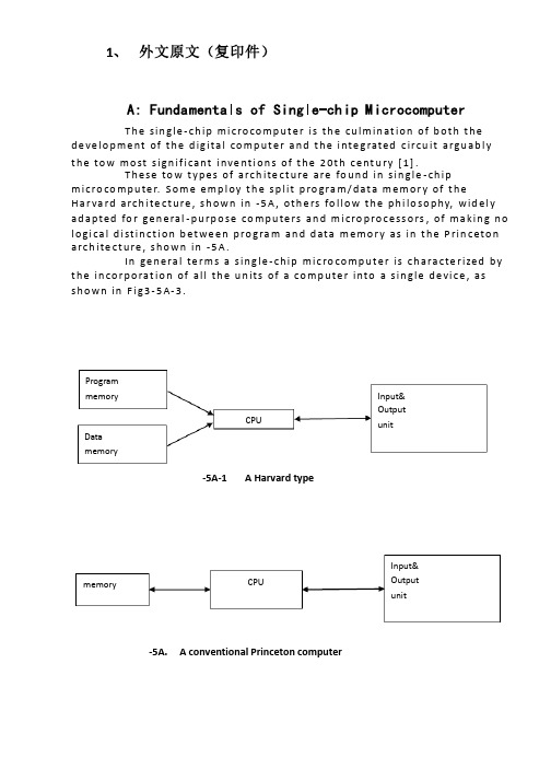
1、 外文原文(复印件)A: Fundamentals of Single-chip MicrocomputerT h e sin gle -ch ip mi c ro co m p u t e r is t h e cu lm in at io n of b ot h t h e d e ve lo p me nt of t h e d ig ita l co m p u t e r a n d t h e i nte g rated c ircu it a rgu ab l y t h e to w mo st s ign if i cant i nve nt i o n s of t h e 20t h c e nt u ry [1].T h ese to w t yp e s of arch ite ct u re are fo u n d in s in gle -ch ip m i cro co m p u te r. S o m e e mp l oy t h e sp l it p ro gra m /d at a m e m o r y of t h e H a r va rd arch ite ct u re , s h o wn in -5A , ot h e rs fo l lo w t h e p h i lo so p hy, wid e l y ad a p ted fo r ge n e ral -p u rp o se co m p u te rs an d m i cro p ro ce ss o rs , of m a kin g n o l o g i ca l d i st in ct i o n b et we e n p ro gra m an d d ata m e m o r y as in t h e P rin c eto n a rch ite ct u re , sh o wn in -5A.In ge n e ra l te r m s a s in g le -ch ip m ic ro co m p u t e r is ch a ra cte r ized b y t h e in co r p o rat io n of all t h e u n its of a co mp u te r into a s in gle d e vi ce , as s h o w n in F i g3-5A-3.-5A-1A Harvard type-5A. A conventional Princeton computerProgrammemory Datamemory CPU Input& Output unitmemoryCPU Input& Output unitResetInterruptsPowerFig3-5A-3. Principal features of a microcomputerRead only memory (ROM).RO M is u su a l l y fo r t h e p e r m an e nt , n o n -vo lat i le sto rage of an ap p l i cat io n s p ro g ram .M a ny m i c ro co m p u te rs a n d m i cro co nt ro l le rs are inte n d ed fo r h i gh -vo lu m e ap p l i cat io n s a n d h e n ce t h e e co n o m i cal man u fa c t u re of t h e d e vi ces re q u ires t h at t h e co nt e nts of t h e p ro gra m me mo r y b e co mm i ed p e r m a n e nt l y d u r in g t h e m a n u fa ct u re of c h ip s . C lea rl y, t h i s imp l ies a r i go ro u s ap p ro a ch to ROM co d e d e ve lo p m e nt s in ce ch an ges can n o t b e mad e af te r m an u fa ct u re .T h i s d e ve l o p m e nt p ro ces s m ay i nvo l ve e mu l at i o n u sin g a so p h ist icated d e ve lo p m e nt syste m wit h a h ard wa re e mu l at i o n capab i l it y as we ll as t h e u s e of p o we rf u l sof t war e to o l s.So m e m an u fa ct u re rs p ro vi d e ad d it i o n a l ROM o p t io n s b y in clu d in g in t h e i r ran ge d e v ic es w it h (o r inte n d ed fo r u s e wit h ) u se r p ro g ram m a b le m e mo r y. T h e s im p lest of t h e se i s u su a l l y d e v i ce wh i ch can o p e rat e in a m i cro p ro ce s so r mo d e b y u s in g s o m e of t h e in p u t /o u t p u t l in es as an ad d res s a n d d ata b u s fo r a cc es sin g exte rn a l m e m o r y. T h is t yp e o f d e vi ce can b e h ave f u n ct i o n al l y as t h e s in gle ch ip m i cro co m p u t e r f ro m wh i ch it i s d e ri ved a lb e it wit h re st r icted I/O an d a m o d if ied exte rn a l c ircu it. T h e u s e of t h e se RO M le ss d e vi ces i s co mmo n e ve n in p ro d u ct io n circu i ts wh e re t h e vo lu m e d o e s n ot ju st if y t h e d e ve lo p m e nt co sts of cu sto m o n -ch ip ROM [2];t h e re ca n st i ll b e a si gn if i cant sav in g in I/O an d o t h e r ch ip s co m pared to a External Timing components System clock Timer/ Counter Serial I/O Prarallel I/O RAM ROMCPUco nve nt io n al m i c ro p ro ces so r b ased circ u it. M o re exa ct re p l a ce m e nt fo rRO M d e v ice s can b e o b tain ed in t h e fo rm of va ria nts w it h 'p i g g y-b a c k'E P ROM(E rasab le p ro gramm ab le ROM )s o cket s o r d e v ice s w it h E P ROMin stead of ROM 。
电信 电流 外文翻译 外文文献 英文文献 直流电机导论负载运行的变压器

电信电流外文翻译外文文献英文文献直流电机导论负载运行的变压器外文文献Introduction to DC Machines The Transformer on loadDC machines are characterized by their versatility. By means of various combination of shunt, series, and separately excited field windings they can be designed to display a wide variety of volt-ampere or speed-torque characteristics for both dynamic and steady state operation. Because of the ease with which they can be controlled , systems of DC machines are often used in applications requiring a wide range of motor speeds or precise control of motor output.The essential features of a DC machine are shown schematically. The stator has salient poles and is excited by one or more field coils. The air-gap flux distribution created by the field winding is symmetrical about the centerline of the field poles. This axis is called the field axis or direct axis.As we know , the AC voltage generated in each rotating armature coil is converted to DC in the external armature terminals by means of a rotating commutator and stationary brushes to which the armature leads are connected. The commutator-brush combination forms a mechanical rectifier, resulting in a DC armature voltage as well as an armature m.m.f. wave which is fixed in space. The brushes are located so that commutation occurs when the coil sides are in the neutral zone , midwaybetween the field poles. The axis of the armature m.m.f. wave then in 90 electrical degrees from the axis of the field poles, i.e., in the quadrature axis. In the schematic representation the brushes are shown in quarature axis because this is the position of the coils to which they are connected. The armature m.m.f. wave then is along the brush axis as shown.. (The geometrical position of the brushes in an actual machine is approximately 90 electrical degrees from their position in the schematic diagram because of the shape of the end connections to the commutator.)The magnetic torque and the speed voltage appearing at the brushes are independent of the spatial waveform of the flux distribution; for convenience we shall continue to assume a sinusoidal flux-density wave in the air gap. The torque can then be found from the magnetic field viewpoint.The torque can be expressed in terms of the interaction of thedirect-axis,Fair-gap flux per pole and the space-fundamental component of theda11armature m.m.f. wave . With the brushes in the quadrature axis, the angle between these fields is 90 electrical degrees, and its sine equals unity. For a P pole machine,P2 T,(),Fda122In which the minus sign has been dropped because the positive direction of the torque can be determined from physical reasoning. The space2fundamental of the sawtooth armature m.m.f. wave is 8/ times itsF,a1peak. Substitution in above equation then givesPCa T,,i,K,idaada2m,Where =current in external armature circuit; ia=total number of conductors in armature winding; Ca=number of parallel paths through winding; mAndPCa K,a2,mIs a constant fixed by the design of the winding.The rectified voltage generated in the armature has already been discussed before for an elementary single-coil armature. The effect of distributing the winding in several slots is shown in figure ,in which each of the rectified sine waves is the voltage generated in one of the coils, commutation taking place at the moment when the coil sides are in the neutral zone. The generated voltage as observed from the brushes is the sum of the rectified voltages of all the coils in series between brushes and is shown by the rippling line labeled e in figure. With a dozen or so commutator asegments per pole, the ripple becomes very small and the average generated voltage observed from the brushes equals the sum of the average values of theerectified coil voltages. The rectified voltage between brushes, known also aas the speed voltage, isPCa e,,W,K,Wadmadm2m,2Where is the design constant. The rectified voltage of a distributed Kawinding has the same average value as that of a concentrated coil. The difference is that the ripple is greatly reduced.From the above equations, with all variable expressed in SI units: ei,TwaamThis equation simply says that the instantaneous electric power associated with the speed voltage equals the instantaneous mechanical power associated with the magnetic torque , the direction of power flow being determined by whether the machine is acting as a motor or generator.The direct-axis air-gap flux is produced by the combinedm.m.f. ,Niffof the field windings, the flux-m.m.f. characteristic being the magnetization curve for the particular iron geometry of the machine. In the magnetization curve, it is assumed that the armature m.m.f. wave isperpendicular to the field axis. It will be necessary to reexamine this assumption later in this chapter, where the effects of saturation are investigated more thoroughly. Because the armature e.m.f. isproportional to flux times speed, it is usually more convenient to express the magnetization curve in terms of the armature e.m.f. at a constant speed . The voltage e for a given flux at any ewm0aa0 other speed is proportional to the speed,i.e. wmwm e,eaa0wm0Figure shows the magnetization curve with only one field winding excited. This curve can easily be obtained by test methods, no knowledge of any design details being required.Over a fairly wide range of excitation the reluctance of the iron is negligible compared with that of the air gap. In this region the flux is linearly proportional to the total m.m.f. of the field windings, the constant of proportionality being the direct-axis air-gap permeance.The outstanding advantages of DC machines arise from the widevariety of operating characteristics which can be obtained by selection of the method of excitation of the field windings. The field windings may be separately excited from an external DC source, or they may beself-excited; i.e., the3machine may supply its own excitation. The method of excitation profoundly influences not only the steady-state characteristics, but also the dynamic behavior of the machine in control systems.The connection diagram of a separately excited generator is given. The required field current is a very small fraction of the rated armature current. A small amount of power in the field circuit maycontrol a relatively large amount of power in the armature circuit; i.e., the generator is a power amplifier. Separately excited generators are often used in feedback control systems when control of the armature voltage over a wide range is required. The field windings of self-excited generators may be supplied in three different ways. The field may be connected in series with the armature, resulting in a shunt generator, or the field may be in two sections, one of which is connected in series and the other in shunt with the armature, resultingin a compound generator. With self-excited generators residual magnetism must be present in the machine iron to get the self-excitation process started.In the typical steady-state volt-ampere characteristics, constant-speed prime movers being assumed. The relation between the steady-state generated e.m.f. and the terminal voltage Vis EatV,E,IRtaaaIWhere is the armature current output and R is the armature circuitaaresistance. In a generator, is large than V; and the electromagnetic Eattorque T is a countertorque opposing rotation.The terminal voltage of a separately excited generator decreases slightly with increase in the load current, principally because of the voltage drop in the armature resistance. The field current of a series generator is the same as the load current, so that the air-gap flux and hence the voltage vary widely with load. As a consequence, series generators are not often used. The voltage of shunt generators drops off somewhat with load. Compound generators are normally connected so that the m.m.f. of the series winding aids that of the shunt winding. The advantage is that through the action of the series winding the flux per pole can increase with load, resulting in a voltage output which is nearly constant. Usually, shunt winding contains many turns 4 of comparatively heavy conductor because it must carry the full armature current of the machine. The voltage of both shunt and compound generators can be controlled over reasonable limits by means of rheostats in the shunt field. Any of the methods of excitation used for generators can also be used for motors. In the typical steady-state speed-torque characteristics, it is assumed that the motor terminals are supplied from a constant-voltage source. In a motor the relation between the e.m.f. generated in the armature and the Eaterminal voltage is VtV,E,IRtaaaWhere is now the armature current input. The generated e.m.f. EIaa is now smaller than the terminal voltage V, the armature current is in the topposite direction to that in a motor, and the electromagnetictorque is in the direction to sustain rotation of the armature.In shunt and separately excited motors the field flux is nearly constant. Consequently, increased torque must be accompanied by a very nearly proportional increase in armature current and hence by a small decrease in counter e.m.f. to allow this increased current through the small armature resistance. Since counter e.m.f. is determined by fluxand speed, the speed must drop slightly. Like the squirrel-cageinduction motor ,the shunt motor is substantially a constant-speed motor having about 5 percent drop in speed from no load to full load. Starting torque and maximum torque are limited by the armature current that canbe commutated successfully.An outstanding advantage of the shunt motor is ease of speed control. With a rheostat in the shunt-field circuit, the field current and flux per pole can be varied at will, and variation of flux causes the inverse variation of speed to maintain counter e.m.f. approximately equal to the impressed terminal voltage. A maximum speed range of about 4 or 5 to 1 can be obtained by this method, the limitation again being commutating conditions. By variation of the impressed armature voltage, very wide speed ranges can be obtained.In the series motor, increase in load is accompanied by increase in the armature current and m.m.f. and the stator field flux (provided the iron is not completely saturated). Because flux increases with load, speed must drop in5order to maintain the balance between impressed voltage and counter e.m.f.; moreover, the increase in armature current caused by increased torque is smaller than in the shunt motor because of the increased flux. The series motor is therefore a varying-speed motor with a markedly drooping speed-load characteristic. For applications requiring heavy torque overloads, this characteristic is particularly advantageous because the corresponding power overloads are held to more reasonable values by the associated speed drops. Very favorable starting characteristics also result from the increase in flux with increased armature current.In the compound motor the series field may be connected either cumulatively, so that its.m.m.f.adds to that of the shunt field, or differentially, so that it opposes. The differential connection is very rarely used. A cumulatively compounded motor has speed-load characteristic intermediate between those of a shunt and a series motor, the drop of speed with load depending on the relative number of ampere-turns in the shunt and series fields. It does not have the disadvantage of very high light-load speed associated with a series motor, but it retains to a considerable degree the advantages of series excitation.The application advantages of DC machines lie in the variety of performance characteristics offered by the possibilities of shunt, series, and compound excitation. Some of these characteristics have been touched upon briefly in this article. Still greater possibilities existif additional sets of brushes are added so that other voltages can be obtained from the commutator. Thus the versatility of DC machine systems and their adaptability to control, both manual and automatic, are their outstanding features.6外文翻译直流电机导论负载运行的变压器直流电机以其多功用性而形成了鲜明的特征。
电气外文文献-翻译

Circuit breaker断路器Compressed air circuit breaker is a mechanical switch equipment, can be i 空气压缩断路器是一种机械开关设备,能够在n normal and special conditions breaking current (such as short circuit cur 正常和特殊情况下开断电流(比如说短路电流)。
rent). For example, air circuit breaker, oil circuit breaker, interference circ 例如空气断路器、油断路器,干扰电路的导体uit conductor for the application of the safety and reliability of the circuit 干扰电路的导体因该安全可靠的应用于其中,breaker, current in arc from is usually divided into the following grades: a 电流断路器按灭弧远离通常被分为如下等级:ir switch circuit breaker, oil circuit breaker, less oil circuit breaker, compr 空气开关断路器、油断路器、少油断路器、压缩空essed air circuit breaker, a degaussing of isolating switch, six sulfur hexaf 气断路器、具有消磁性质的隔离开关、六氟luoride circuit breaker and vacuum breaker. Their parameters of voltage, 化硫断路器和真空断路器。
他们的参数有电压等级、current, insulation level of breaking capacity, instantaneous voltage off ti 开断容量的电流、绝缘等级开断时间的瞬时电压恢复和me of recovery and a bombing. Breaker plate usually include: 1 the maxi 轰炸时间。
翻译

Protection Strategies for Medium Voltage Direct Current Microgridat a Remote Area Mine Site偏远地区矿场的中压直流微电网的保护策略摘要: 文章介绍了在一个偏远地区中压直流电(MVDC)微型智能电网的保护策略。
微型智能电网的运行是为了给敏感负载提供大功率的电能质量和可靠性,同时提高采矿设备的能源效率。
MVDC微型智能电网,当地各种分布式能源资源(各级)已经被使用其中包括光伏(PV)数组、风力涡轮机、燃料电池堆栈,能量存储系统和移动柴油发电机。
对于输电线路保护,采用通信为基础的并且带有固体电子继电器的差动保护方案来隔离MVDC微电网的故障部分。
这进一步强化了直流过电流保护作为备份。
早期的研究工作忽视了直流系统的后备保护。
此外,以沟通为基础的直流方向过电流保护继电器被同时用于电源和负载保护来支持双向功率流。
MA TLAB / Simulink建模和仿真结果被提出和讨论来说明该系统的可靠性和安全性。
关键词:电路故障,延迟,分布式发电,能量存储,微网,矿业,过电流保护,电压控制,风力涡轮机I.INTRODUCTION引文矿点往往在偏远地方的矿产资源丰富,但很少有一个庞大而完善的电网基础设施。
但是,必须有一个安全的和可靠的电力供应对于有效和可靠地运行的开采作业是很重要的。
最近的技术发展趋势表明,在中压直流(MVDC )系统方向的兴趣在不断增加,同时在一些刊物上也可以获得。
这导致了各种电力设备制造商推出新的产品进入市场,例如引用。
在不久的将来,许多其它MVDC系统有望成为可能。
因此,当务之急是以全面的方式在用于工业电力系统MVDC系统的保护问题进行了研究。
本文提出了MVDC微电网为偏远地区矿场提供可靠和安全的电力供应保护策略。
安装在位于较远主电网长期输电线路被公认为是昂贵的。
因此,本文探讨了一种利用当地现有的能源资源的微电网孤岛MVDC的可行性。
- 1、下载文档前请自行甄别文档内容的完整性,平台不提供额外的编辑、内容补充、找答案等附加服务。
- 2、"仅部分预览"的文档,不可在线预览部分如存在完整性等问题,可反馈申请退款(可完整预览的文档不适用该条件!)。
- 3、如文档侵犯您的权益,请联系客服反馈,我们会尽快为您处理(人工客服工作时间:9:00-18:30)。
英文文献原文A sensorless and simple controller for VSC basedHVDC systemsAbstract: Voltage source converter high-voltage direct current (VSC-HVDC) is a new power transmission technology preferable in small or medium power transmission. In this paper we discuss a new control system based on space vector modulation (SVM) without any voltage line sensors. Using direct power control (DPC) SVM and a new double synchronous reference frame phase-locked loop (DSRF-PLL) approach, the control system is resistant to the majority of line voltage disturbances. Also, the system response has accelerated by using a feed forward power decoupled loop. The operation of this control strategy was verified in a SIMULINK/MATLAB simulation environment. To validate this control system, a 5 kV·A prototype system was constructed. Compared to the original controllers, the current total harmonic distortion (THD), the active and reactive deviations and the DC voltage overshoot were lowered by 2.5%, 6.2% and 8%, respectively. The rectifier power factor in the worst condition was 0.93 and the DC voltage settling time was 0.2 s.Key words: Voltage source converter high-voltage direct current (VSC-HVDC), Space vector modulation (SVM), Direct power control (DPC), HVDC Light1 INTRODUCTIONVoltage source converter high-voltage direct current (VSC-HVDC), controlled by pulse width modulation (PWM), can supply power to both active and passive electrical systems. The introduction of VSC and PWM makes possible fast and flexible control of power flow and more convenient operation of power systems. Besides, this advancement, compared with conventional HVDC, mitigates harmonics in AC current and AC voltage greatly and improves power factors of the connected AC systems (Li GK et al., 2005). VSC-HVDC or HVDC Light, in recent years, have successfully been commercially commissioned in such fields as supplying power to remote isolated loads, empowering urban centers, connecting distributed generation sources, linking two asynchronous electrical power systems, improving power quality, and so on (Asplund, 2000; Li et al., 2003).The advantages of a VSC based HVDC system are (Asplund, 2000): (1) only a small filter is required to filter high frequency signal components;(2) there is no commutation failure problem; (3) reactive power compensation is not required; (4) there is no restriction on multiple in-feeds; etc.There are various control methods for VSC based HVDC systems. Zhang et al.(2002) used the inverse steady state model controller to trace the operating point and adopted two decoupled controlling loops to eliminate the steady state deviation. Chen et al.(2004) proposed a steady-state controller design scheme based on dq0-axis. Zhang et al.(2002) and Chen et al.(2004) assumed that the two terminals of VSC-HVDC have been connected to an infinite bus system. But one terminal of VSC-HVDC may be connected to a generator and, as in Asplund et al. (1997), an HVDC Light system connects the generator (such as an offshore wind farm) to the grid. These strategies focus on control of the HVDC system itself and do not consider the interaction between AC and DC systems. Hu et al.(2004) presented an optimal coordinated control strategy between the generator excitation and VSC-HVDC, whereas the derivation of control law is complicated. Hu et al.(2005) applied a genetic algorithm (GA) to optimize parameters of the controller after determining them. Ooi and Wang (1991) and Zhang and Xu (2001) used a phase and amplitude control (PAC) technique for VSC based HVDC applications. Li GI et al.(2005) proposed a nonlinear control for an HVDC Light system. These methods have used voltage and current sensors.A direct power control (DPC) strategy based on virtual flux, called VF-DPC, provides sinusoidal line current, lower harmonic distortion, a simple and noise-robust power estimation algorithm and good dynamic response (Rahmati et al., 2006). However, the VF-DPC scheme has the following well-known disadvantages (Malinowski et al., 2001; 2004): (1) variable switching frequency (difficulties of LC input filter design), (2) high sampling frequency needed for digital implementation of hysteresis comparators, (3) necessity for a fast microprocessor and A/D converters.Therefore, there is no tendency to implement VF-DPC in industry. All the above drawbacks can be eliminated when, instead of the switching table, space vector modulation (SVM) is applied.DPC is a method based on instantaneous direct active and reactive power control (Malinowski et al., 2004). In DPC there are no internal current control loops and no PWM modulator block. Moreover, the turn-on and turn-off commands of the static switches of the converters are generated by SVM. Use of space vector modulation causes lower current harmonics, relatively high regulation and stability of output voltage and obtains a higher modulation factor relative to sinusoidal modulation (Malinowski et al., 2004). Also, it can easily be implemented in a DSPbased system.Double synchronous reference frame phase-locked loop (DSRF-PLL) based on VF causes this control system to be resistant to the majority of line voltage disturbances. This assures proper operation of the system for abnormal and failure grid conditions.In this paper a new control strategy is proposed for VSC-HVDC. In this strategy, the reactive power and output DC voltage in the rectifier station and the reactive and active powers in the inverter station are controlled, separately. Also, the DPC rectifier equations (Malinowski et al., 2004) have been developed for the inverter. For more accuracy in high power, the second order parameter is included in the rectifier and the inverter equations. Active and reactive power feed forward decoupling are used for accelerating the system response. Finally, DPC is applied to the rectifier and inverter stations of VSC-HVDC.The operation of this control strategy is verified in a SIMULINK/MATLAB simulation environment for steady state, active and reactive power variations, single-line-to-ground faults and unbalanced sources at the rectifier and the inverter stations. Also, this control strategy is applied to a 5 kV ·A prototype system which is verification that this control strategy has a fast response and strong stability.2 CONTROL of VSC BASED HVDC SYSTEM2.1 VSC based HVDC systemVSC-HVDC involves two voltage source converters with the same configuration, linking with a dc transmission line or cable (Fig.1). There are four control variables represented by dcr U ,r q ,i p and i q for this system. In this paper, a rectifier station is chosen to control DC-bus output voltage of rectifier (dcr U ). Also, reactive power (r q ) and inverter station are set to control active power (i p ) and also reactive power (i q ). R c is the equivalent resistance of the transmission cable and can be practically neglected. Thus we may write dcr dci dc U U U ≈= .Fig.1 A physical model for a VSC based HVDC system2.2 Virtual-flux estimator for rectifier and inverterFrom the economical point of view, and for simplicity, more reliability and separation of power stage and control, AC line voltage sensors are replaced by a flux estimator (Malinowski et al., 2004).The basic model of a VSC station is shown in Fig.2. If D a, D b, and D c are the duty cycles of S a, S b, and S c signals, respectively, U dc is the converter DC voltage, and u L α and u L β are line voltage in α-β coordinates, then the related flux of AC voltage, L ψ, can be written as(Malinowski et al., 2004).L L L L L u dt u dt ααββ⎡⎤ψ⎡⎤⎢⎥ψ==⎢⎥ψ⎢⎥⎣⎦⎣⎦⎰⎰ (1) Also, the converter voltage equations in α-β coordinates are: ()21,32S dc a b c u U D D D α⎡⎤=-+⎢⎥⎣⎦(2) ().2S dc b c u U D D β=- (3)Fig.2 Basic model of a voltage source converter2.3 Direct power controlActive and reactive power in the rectifier and the inverter stations are estimated using the line current vectors (),L L i i αβand estimated virtual flux (),L L αβψψin α-β coordinates (Malinowski et al., 2004):(),L L L L p i i αββαω=ψ-ψ (4)().L L L L q i i ααββω=ψ+ψ (5)2.4 Rectifier control designThe full control algorithm of the proposed control system is presented in Fig.3. The DPC-SVM uses closed-loop power control. In the rectifier station, reference reactive power (q refr) is set to zero for unity-power-factor operation. In an ideal case, the active power in the rectifier station and the active power in the inverter station are equal, and no storage elements are needed. Nevertheless, in real systems differences between these active powers are inevitable, and these differences are absorbed by the DC link capacitor and are reflected in fluctuations of the DC link voltage. Thus, the reference active power (p ref r) at the side of the rectifier is the sum of the outer proportional-integral (PI) dc voltage controller and estimated active power in the inverter station (p i).Fig.3 Control scheme for a VSC based HVDC system with the rectifier and inverterstationsAccording to the current direction, the line voltage u Lr can be expressed as the sum of the inductor voltage u Ir, the resistor voltage u Rr and the rectifier voltage u Sr (Rahmati et al., 2006):.Lr Sr Ir Rr u u u u =++ (6)By considering Eq.(1), the estimated virtual fluxes are:()(),Lr est Sr r r u R i dt L i ααααψ=++⎰ (7)()().Lr est Sr r r u R i dt L i ββββψ=++⎰ (8)2.5 Inverter control designIn the inverter station, reference reactive power (q ref i) and reference active power (p ref i) are set to network demand. According to the current direction, the inverter voltage u Si can be expressed as the sum of the inductor voltage u Ii, the resistor voltage u Ri and the line voltage u Li at the side of the inverter. The estimated virtual fluxes are (Rahmati et al., 2006):()(),Li est Si i i u Ri dt Li ααααψ=--⎰ (9)()().Li est Si i i u Ri dt Li ββββψ=--⎰ (10)3 CONCLUSIONThis paper proposes a new method for controlling a VSC based HVDC system which has been connected between two distribution systems with different frequencies. This method is effective in damping system oscillations quickly, and enhances power quality when power flow is reversed. VF and DSRF-PLL cause this control system to be resistant to the majority of line voltage disturbances.This method has such advantages as good dynamic response, suitable power quality under abrupt changes in active and reactive powers, a simple power estimation algorithm, sinusoidal line currents and also the unity power factor of the rectifier. Moreover, by this method no line voltage sensors are required.英文翻译轻型直流输电系统的无传感器简单控制摘要:轻型直流输电(VSC-HVDC)是一种新的电力传输技术,适用于在中小功率传输。